Table of Contents
Advertisement
Quick Links
Installation, Operation, and Maintenance
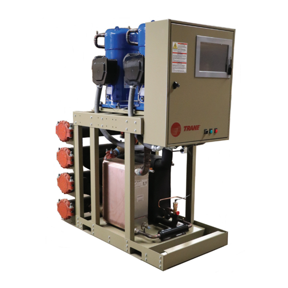
Cold Generator™ Compact Chiller
Series
20 to 85 Tons (60 Hz)
R-410A
Model
CICD
Only qualified personnel should install and service the equipment. The installation, starting up, and servicing of
heating, ventilating, and air-conditioning equipment can be hazardous and requires specific knowledge and training.
Improperly installed, adjusted or altered equipment by an unqualified person could result in death or serious injury.
When working on the equipment, observe all precautions in the literature and on the tags, stickers, and labels that are
attached to the equipment.
June 2022
SAFETY WARNING
CG-SVX044F-EN
Advertisement
Table of Contents

Related Manuals for Trane Cold Generator CG-SVX044F-EN


Summary of Contents for Trane Cold Generator CG-SVX044F-EN
- Page 1 Installation, Operation, and Maintenance Cold Generator™ Compact Chiller Series 20 to 85 Tons (60 Hz) R-410A Model CICD SAFETY WARNING Only qualified personnel should install and service the equipment. The installation, starting up, and servicing of heating, ventilating, and air-conditioning equipment can be hazardous and requires specific knowledge and training. Improperly installed, adjusted or altered equipment by an unqualified person could result in death or serious injury.
- Page 2 When working with or around hazardous chemicals, these compounds have the same potential impact to the ALWAYS refer to the appropriate SDS and OSHA/GHS environment. Trane advocates the responsible handling of all (Global Harmonized System of Classification and refrigerants-including industry replacements for CFCs and Labeling of Chemicals) guidelines for information on HCFCs such as saturated or unsaturated HFCs and HCFCs.
- Page 3 Copyright This document and the information in it are the property of Trane, and may not be used or reproduced in whole or in part without written permission. Trane reserves the right to revise this publication at any time, and to make changes to its content without obligation to notify any person of such revision or change.
-
Page 4: Table Of Contents
Table of Contents Model Number Descriptions Unit Start-Up Procedures ....5 ....35 Pre-Start . -
Page 5: Model Number Descriptions
Model Number Descriptions Digits 1 to 4 — Model Digit 19 — Evaporator Control Valves Digit 27 — Service Options CICD= Compact Indoor Chiller Manual Balancing Isolating Valves None Motorized Chilled Water Isolating LED Lighted Control Cabinet Digits 5 to 7 — Nominal Capacity Valve Digit 28 —... - Page 6 Model Number Descriptions Digit 38 — Water Strainer(s) Digit 44 — Shipping Options None Framed Crate with Plastic Wrap Chilled Water Flow Wye Strainer (Non-Shrink) Chilled Water Wye Strainer with Fully Enclosed Crate Installation Kit Digit 45 — Warranty Condenser Water Flow Wye Standard Warranty Strainer Condenser Water Wye Strainer...
-
Page 7: General Information
General Information Unit Description ™ Model CICD Cold Generator Compact Series water-cooled chillers are designed for installation on a prepared surface in a suitable, weatherproof location above freezing (32°F). Each unit consists of one or two independent refrigerant circuits, two scroll compressors, a single or dual circuited brazed plate evaporator, a single or dual circuited brazed plate or shell-and- tube condenser and control box with integral control panel—all... - Page 8 General Information Unit Components Figure 1. Unit components Keypad or Touchscreen Controller Display Locking Door Detachable Water OFF/AUTO Switch, Header Frame RUN Light, ALARM Light Easily Accessible Condenser for Easy Cleaning Brazed Plate or Shell and Tube Condenser Single or Dual Refrigeration Circuit(s) Manual or Motorized...
-
Page 9: Pre-Installation
Request an immediate, joint inspection of the damage with the carrier and the consignee. • Notify the Trane sales representative and arrange for repair. However, do not repair the unit until damage is inspected by the carrier’s representative. -
Page 10: Electrical Data
Electrical Data Table 2. Electrical data Compressor Wiring # of Minimum Refrigerant Nominal Circuit Max Fuse Recommended Dual Size Rated Voltage Circuits Tons (each) (each) Ampacity Size Element Fuse Size 200-230/60/3 460/60/3 1 or 2 10/10 575/60/3 200-230/60/3 460/60/3 1 or 2 15/15 575/60/3 200-230/60/3... -
Page 11: Dimensions And Weights
Dimensions and Weights Dimensions Figure 2. CICD unit dimensions, brazed plate condenser CG-SVX044F-EN... - Page 12 Dimensions and Weights Figure 3. CICD unit array dimensions, brazed plate condenser CG-SVX044F-EN...
- Page 13 Dimensions and Weights Figure 4. CICD unit dimensions, shell and tube condenser POWER WIRE ENTRY CONTROL PANEL SHELL and TUBE CONDENSER 1 3/8" 45" 8 3/4" 7/8" BRAZED PLATE 29 3/4" EVAPORATOR 2x 29 3/4" 31 1/2" 3/4" 59 7/8" Footprint 60 5/8"...
- Page 14 Dimensions and Weights Figure 5. CICD unit array dimensions, shell and tube condenser CG-SVX044F-EN...
- Page 15 Dimensions and Weights Figure 6. CICD unit dimensions, remote condenser POWER WIRE ENTRY CONTROL PANEL BRAZED PLATE EVAPORATOR 1 3/8" 45" 8 3/4" 4 3/4" 7/8" 31 1/2" 29 3/4" 7/8" Footprint 3/4" 59 7/8" 60" Customer connections 6" S/40 pipe 76"...
- Page 16 Dimensions and Weights Figure 7. CICD unit array dimensions, remote condenser CG-SVX044F-EN...
-
Page 17: Clearances
Dimensions and Weights Clearances • Two units facing each other or other live parts require a clearance of 48 inch. Notes: • 36 inch clearance is recommended above the chiller. • Clearance of 42 inch is required in front of chiller to other •... - Page 18 Dimensions and Weights Figure 9. Clearance — CICD array chiller application (all condenser options) 24" Recommended 3/4" Min. 3/4" Min. 36" 36" Recommended Recommended 42" Figure 10. Clearance needed to remove chiller from array— CICD array chiller application (all condenser options) 24"...
- Page 19 Dimensions and Weights Figure 11. Single point power distribution panel dimensions CG-SVX044F-EN...
-
Page 20: Weights
Dimensions and Weights Weights Table 3. CICD unit weights Shipping Weight Operating Weight Brazed Plate Shell-and-Tube Brazed Plate Shell-and-Tube Condenser Condenser Remote Condenser Condenser Condenser Remote Condenser Size 1326 1467 1069 1525 1688 1168 1495 1760 1205 1720 2025 1320 1775 1970 1420... -
Page 21: Installation Mechanical
80°F and 145°F through all steady state, part load and transient operating conditions. Trane Foundation recommends the optional factory-installed integral water regulating valve controlled by the unit controller. -
Page 22: Clearances
Installation Mechanical Clearances Figure 12. CICD rigging, fork lift pockets Provide adequate space around each unit for unrestricted Spreader Bar access for installation and maintenance. Unit dimensions are given in the Dimensions and Weights chapter. It is critical that Lifting Straps adequate space is provided for service and maintenance of evaporator, condenser and compressor. -
Page 23: Access Restrictions
Installation Mechanical Access Restrictions Forklifting Procedure Important: Step 1 through Step 4 must be followed to lift All CICD units are designed to pass through a standard 36 inch unit using a forklift. doorway. See outline drawings for other important dimensions. Steps to be taken when forklift is used: Compressor Mounting 1. -
Page 24: Minimum Water Volume For A Process Application
Installation Mechanical systems with a rapidly changing load profile the volume should additional chiller protection, install and wire the flow switch in be increased. series with chilled water pump interlock for the chilled water circuits. See “Required Chilled Water Flow Switch,” p. If the installed system volume does not meet the above Specific connection and schematic wiring diagrams ship with recommendations, the following items should be given careful... - Page 25 Minimum system volume requirements are indicated in Figure 4, p. 25. Special applications may deviate from these numbers as directed by Trane engineering. Operation below these volumes will cause unacceptable system control problems and the potential for evaporator failure. Pressure Drop Curves Figure 13.
- Page 26 Installation Mechanical Figure 14. Condenser pressure drop Brazed Plate Condenser Flow vs Pressure Drop 60.00 25.00 50.00 20.00 40.00 15.00 30.00 10.00 20.00 5.00 10.00 0.00 0.00 0.00 50.00 100.00 150.00 200.00 250.00 300.00 350.00 Flowrate (gpm) CICD030 CICD045 CICD055 CICD065 CICD075 Figure 15.
- Page 27 Chemical treatment water treatment, if any, is required. Trane assumes no of the chilled water loop is required and must be performed by a responsibility for equipment failures which result from untreated or improperly treated water, or saline or qualified water treatment specialist.
- Page 28 Saturated discharge Waterborne Debris! temperature must be maintained between 80°F and 145°F. Trane offers an optional factory installed water regulating valve To prevent condenser damage, pipe strainers must be that is controlled by unit controller. The optional water...
- Page 29 Installation Mechanical temperature is 65°F. Condenser piping must be in accordance with all local and national codes. Condenser piping components generally function identically to those in the evaporator piping system. In addition, cooling tower systems may include a manual or automatic bypass valve that can alter water flow rate to maintain condensing pressure.
-
Page 30: Installation Electrical
Installation Electrical Checking the Power Supply WARNING Electrical power to the unit must meet stringent requirements Proper Field Wiring and Grounding for the unit to operate properly. Total voltage supply and Required! voltage imbalance between phases should be within the tolerances listed in this manual. -
Page 31: Equipment Grounding
Installation Electrical Equipment Grounding Setting the Proper Electrical Phase Sequence Proper compressor motor electrical phasing can be quickly NOTICE determined and, if necessary, corrected before starting the unit. Use Copper Conductors Only! Use a quality instrument, such as an Associated Research Model 45 Phase Sequence indicator or equivalent and follow Failure to use copper conductors could result in equipment damage as unit terminals are not designed... -
Page 32: Control Power Supply
Installation Electrical Control Power Supply Condenser Water Loss of Flow Protection The CICD controller logic will sense a loss of flow through the A fused, panel-mounted control power transformer is standard. condenser. No condenser water flow switches are necessary Replacement fuse information is listed on the “Fuse Schedule” with the standard standalone CICD controller configuration. -
Page 33: Controls Interface
Controls Interface Unit Controller Unit Controller — General Software Installation and Setup The CICD controller is a rugged microprocessor-based controller designed for the hostile environment of the HVAC/R Downloading and Installing Unit industry. It is designed to be the primary manager of the CICD Controller (MCS-Connect) Software product. - Page 34 Controls Interface Downloading and Viewing Graphs minutes. After the reboot is completed, close and restart the MCS-CONNECT software to reestablish communication with The unit controller continuously records and stores sensor the chiller. input and relay/analog output data. This data is collected in 10- second (default) intervals.
-
Page 35: Unit Start-Up Procedures
Disconnect all electric strainers must be installed in the water supplies to power, including remote disconnects before servicing. protect components from water born debris. Trane is Follow proper lockout/tagout procedures to ensure the not responsible for equipment damage caused by power can not be inadvertently energized. -
Page 36: Checking Operating Conditions
Unit Start-Up Procedures Checking Operating Conditions superheat, sub-cooling and operating NOTICE pressure. Evaporator/Condenser Damage! • Once oil level, amp draw and operating pressures have stabilized, measure system suction superheat. Water (fluid) flow must be established in evaporator and condenser before adding refrigerant, removing •... -
Page 37: Shut Down
Shut Down Normal Unit Shutdown Figure 18. Normal unit shutdown Extended Shutdown Procedure If the system is taken out of operation for long periods of time, use this procedure to prepare the system for shutdown. 1. Test condenser and high side piping for refrigerant leakage. 2. -
Page 38: Unit Restart
Shut Down Unit Restart Unit Restart After Extended Shutdown Use this procedure to prepare the system for restart after an extended shutdown. NOTICE Compressor Failure! To protect compressors from premature failure the unit must be powered and crankcase heaters energized at least 24 hours BEFORE compressors are started. -
Page 39: Maintenance
Maintenance Monthly Maintenance WARNING Ensure the unit has been operating for about 10 minutes and Hazardous Service Procedures! the system has stabilized, check operating conditions and complete the checkout procedures that follow. Failure to follow all precautions in this manual and on the tags, stickers, and labels could result in death or •... -
Page 40: Heat Exchanger Maintenance
Maintenance Oil Level Compressor Operational Noises While the compressor is running, the oil level may be below the At low ambient startup: When the compressor starts up under sight glass but still visible through the sight glass. The oil level low ambient conditions, the initial flow rate of the compressor should NEVER be above the sight glass! is low. - Page 41 Maintenance Cleaning in Place (CIP) Procedure stainless steels, it's relatively inexpensive and can be disposed by incineration. Start Acetic Acid 1. Shut off relevant pumps Dissolves lime scale, but doesn't remove iron oxide deposits. 2. Shut off the primary side's valves Since it's weaker than formic acid, it is preferred where long 3.
-
Page 42: Wiring
Wiring Figure 19. CICD wiring schematic CG-SVX044F-EN... - Page 43 Wiring Figure 20. CICD wiring schematic (continued) CG-SVX044F-EN...
- Page 44 Wiring Figure 21. CICD dual circuit secondary unit wiring schematic CG-SVX044F-EN...
- Page 45 Wiring Figure 22. CICD dual circuit secondary unit wiring schematic (continued) CG-SVX044F-EN...
- Page 46 Wiring Figure 23. Field wiring — CICD single unit, single circuit CG-SVX044F-EN...
- Page 47 Wiring Figure 24. Field wiring — CICD single unit, dual circuit CG-SVX044F-EN...
- Page 48 Wiring Figure 25. Field wiring — CICD array with manager/subordinate controller, single circuit modules CG-SVX044F-EN...
- Page 49 Wiring Figure 26. Field wiring — CICD array with manager/subordinate controller, dual circuit modules CG-SVX044F-EN...
- Page 50 Wiring Figure 27. Field wiring — CICD array with supervisory controller, single circuit modules CG-SVX044F-EN...
- Page 51 Wiring Figure 28. Field wiring — CICD array with supervisory controller, dual circuit modules CG-SVX044F-EN...
- Page 52 Wiring Figure 29. Field wiring — CICD array control panel Ethernet Cables From Ethernet Cable From Power Cord From Each Chiller Module Wireless Router Wireless Router (Field Provided) (Factory Provided) (Factory Provided) 16 Port Ethernet Switch PANEL GROUND REQUIRED Black 115 VAC Circuit Breaker Shield...
-
Page 53: Warranty
Appendix A Warranty • Products which have defects or damage which result from improper installation, wiring, electrical imbalance characteristics or maintenance (including, without I. LIMITED PRODUCT WARRANTY & SERVICE POLICY limitation, defects or damages caused by voltage surges, Napps Technology Corporation (NAPPS) warrants for a period inadequate voltage conditions, phase imbalance, any form of twelve (12) months from date of original shipment that all of electrical disturbances, inadequate or improper... - Page 54 Appendix A PRODUCTS OR ANY PARTS THEREFORE AND IS MADE EXPRESSLY IN LIEU OF ANY OTHER WARRANTIES, BY COURSE OF DEALING, USAGES OF TRADE OR OTHERWISE, EXPRESSED OR IMPLIED, INCLUDING BUT NOT LIMITED TO ANY IMPLIED WARRANTIES OF FITNESS FOR ANY PARTICULAR PURPOSE OR OF MERCHANTABILITY UNDER THE UNIFORM COMMERCIAL CODE.
-
Page 55: Piping System Flushing Procedure
Appendix B Piping System Flushing Water Treatment Requirements Procedure Supply water for both the chilled water and condenser water Prior to connecting the chiller to the condenser and chilled circuits shall be analyzed and treated by a professional water water loop, the piping loops shall be flushed with a detergent treatment specialist who is familiar with the operating and hot water (110-130°F) mixture to remove previously conditions and materials of construction specified for the... - Page 56 For more information, please visit trane.com or tranetechnologies.com. Trane has a policy of continuous product and product data improvement and reserves the right to change design and specifications without notice. We are committed to using environmentally conscious print practices.