
Related Manuals for Axminster AWHBS350N


Summary of Contents for Axminster AWHBS350N
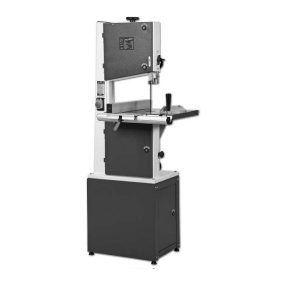
- Page 1 Code: 501246 AWHBS350N Bandsaw Axminster Tool Centre, Unit 10 Weycroft Avenue, Axminster, Devon EX13 5PH axminster.co.uk...
-
Page 2: Declaration Of Conformity
Index of Contents Page No Index of Contents Declaration of Conformity What’s Included General Instructions for 230V Machines 04-05 Specification Unpacking Cabinet Assembly 06-07-08 Assembling the Bandsaw to the Cabinet Assembly 10-11 Illustration and Parts Description 12-13-14-15-16-17-18-19 Setting Up the Saw Setting the Blade Guides Setting the Fence Operating Instructions... -
Page 3: What's Included
What’s Included Quantity Item Model Number MJ343B 1 No. Bandsaw 1 No. Bandsaw Blade 2480mm long 4 TPI Skip assembled in the saw (not tensioned) 1 No. Saw Table 1 No. Fence Guide and Extension 1 No. Mitre Guide 1 No. Packet containing the On/Off Switch Safety Shroud 1 No. -
Page 4: General Instructions For 230 V Machines
General Instructions for 230 V Machines Keep the machines clean; it will enable you to more Good Working Practices/Safety easily see any damage that may have occurred. The following suggestions will enable you to Clean the machine with a damp soapy cloth if needs observe good working practices, keep yourself and be, do not use any solvents or cleaners, as these may fellow workers safe and maintain your tools and... -
Page 5: Specification
Above all, OBSERVE…. make sure you know what very specialised machines for working in these areas, is happening around you, and USE YOUR COMMON THIS IS NOT ONE OF THEM. SENSE. Specification Model AWHBS350N Rating Hobby Power 750W (230V) Blade Speed 600 & 720 m/min... -
Page 6: Cabinet Assembly
Unpacking Your saw is packed in the box partially assembled. tip the box up so that the base of the saw is to the This is to ensure that the components are inserted ground, remove all the polystyrene packaging from in the correct positions. - Page 7 Cabinet Assembly Step 3 Cabinet door Place the door between the support and Spring hinge pin connecting plates & insert the two spring hinge pins into pre-drilled holes. Step 4 Side plate Support plate Locate the side plate and lightly secure using Locate and secure the other support plate.
- Page 8 Cabinet Assembly Step 5 Screw the four rubber feet into each corner Attaching the rubber foot to to the base of the cabinet. the base of the cabinet. Step 6 Tighten all the M6x12 nuts, bolts and washers before mounting the bandsaw.
-
Page 9: Assembling The Bandsaw To The Cabinet
When mounting the unit, we strongly advise you get the assistance of another person because of the weight of the machine. Bandsaw Two Man lift M8x40 bolt & washers Cabinet Please Note: the Illustration above shows the AWHBS350N with the table already assembled to the bandsaw for clarity. - Page 10 Assembly Mounting the saw table The saw table can be fitted without removing the blade, however, if you would feel more comfortable not having to manoeuvre the table around the blade (the table is quite heavy), remove the blade by opening the top and bottom covers, release the tension on the blade by backing off the tensioning wheel Fig 1 Fig 2...
- Page 11 Assembly blade. Any slight discrepancy can be taken out by Fitting the guide fence loosening the 4 butterfly bolts that secure the blade of the guide fence to the clamping body, adjust and Fit the guide fence by clipping the rear clamp over re-tighten.
-
Page 12: Illustration And Parts Description
Illustration and Parts Description Blade tensioning wheel Fig 8 Upper cover door latches Upper cover door Upper blade guide height clamp Upper blade guide and guard Main saw frame Saw table insert On/Off button and switch shroud Mitre fence Guide fence Lock lever Fence guide rail Lower cover door... - Page 13 Illustration and Parts Description Main saw frame The main body of the machine that all the other parts are mounted upon. Upper and lower The two doors that cover the upper and lower saw wheel compartments. cover doors There are interlocks fitted to both doors so that the machine cannot operate if either door is left open.
- Page 14 Illustration and Parts Description Blade tensioning wheel Tracking control knob Upper blade guide height adjusting wheel Guide fence Mitre fence Saw table Tilt quadrant Tilt mechanism Quadrant clamp housing Idler wheel Motor adjusting knob Dust extraction outlet Fig 9...
- Page 15 Illustration and Parts Description Lower blade The lower blade guide assembly is mounted on the main saw frame below the guide and table, it mounts the rear thrust bearing and two side guides that keep the blade guard stable (straight and untwisted) below the table during the sawing operation. The lower guard is two half red plastic enclosures that screws to the guide assembly, and shields the blade between the underside of the table and the top of the lower saw wheel compartment.
- Page 16 Illustration and Parts Description Blade tensioning wheel Fig 10a Fig 10b Upper wheel mounting assembly Upper saw wheel Upper blade guide height mechanism Upper blade guide height clamp Fig 10c Lower saw wheel Micro switch Idler wheel adjusting knob Fig 10d Fig 10 Drive belt tensioning idler wheel...
- Page 17 Illustration and Parts Description Lower saw The lower saw wheel and integral pulley wheel is likewise mounted on double wheel bearings, onto an axle that is mounted to a fixed base plate. The base plate, triangular in shape, is bolted to the rear face of the lower saw wheel compartment. There are no adjustment mechanisms for the lower saw wheel.
- Page 18 Illustration and Parts Description Fig 11a Tilt quadrant Fig 11 Saw table Scale Tilt scale pointer Table preset Tilt mechanism clamp Quadrant housing level stop Fig 12 Unlock Lock...
- Page 19 Illustration and Parts Description Fig 13a Mitre scale Saw table insert Mitre fence Fig 13 Typ. 2‘T’ Slot Pointer Fig 14 Upper blade guide height clamp Upper door latch...
-
Page 20: Setting Up The Saw
Setting Up the Saw and the blade appears to be tracking correctly (in one place). You can check this by holding a marker, DISCONNECT THE SAW e.g. a pencil, close to the back of the blade (approach FROM THE MAINS SUPPLY from the back of the blade only) and check that the gap remains constant. -
Page 21: Setting The Blade Guides
Setting the Blade Guides DISCONNECT THE SAW FROM THE MAINS SUPPLY Lower the upper blade guide to approximately 1 1/2”(38mm) above the table. Clamp in place. NOTE: The table has been removed for clarity. Loosen the bolt holding the guide assembly in place (A) and adjust the back to front position so that the leading edges of the side guide bearings are approximately 1.5 mm behind the gullets of the saw... -
Page 22: Setting The Fence
Setting the Fence To make sure the guide fence is at 90˚line up the guide fence with the edge of the table’s ‘T’ slot. If you find that the fence is out of alignment follow the steps below: • Clamp down the fence by pushing the locking lever down. •... -
Page 23: Operating Instructions
Operating Instructions 1. Make sure you have read and fully understood the Do not let go of the work piece, if you have to change general instructions and safety precautions your grip, make sure one hand is holding the material that are printed in the preceding pages of this at all times. -
Page 24: Changing The Saw Blade
Changing the Saw Blade assembly and the captive stub axle of the drive belt tensioner in its slot could likewise be lightly oiled. If DISCONNECT THE SAW you are fitting a new blade; it will have been supplied FROM THE MAINS SUPPLY to you “folded”... -
Page 25: Routine Maintenance
Routine Maintenance Daily •Keep the machine clean. •Check the saw blade for missing teeth and cracks in the fabric. •Spray oil the bare metal surfaces. Weekly •Open the top & bottom wheel covers and clean out all saw dust. Monthly •Open the lower &... -
Page 26: Parts Breakdown/List
Parts Breakdown/List... -
Page 27: Parts Drawing/List
Parts Drawing/List... - Page 28 Parts Drawing/List...
- Page 29 Parts Drawing/List...
- Page 30 Notes...
- Page 31 Notes...
- Page 32 Please dispose of packaging for the product in a responsible manner. It is suitable for recycling. Help to protect the environment, take the packaging to the local recycling centre and place into the appropriate recycling bin. Only for EU countries Do not dispose of electric tools together with household waste material.