
Related Manuals for Sony UWP-X5


Summary of Contents for Sony UWP-X5
- Page 1 2-698-941-31 (1) Wireless Microphone Package Operating Instructions Before operating the unit, please read this manual thoroughly and retain it for future reference. UWP-X5 ©2007 Sony Corporation...
-
Page 3: Table Of Contents
Table of Contents Configuration of the Package ..........4 Features ...................5 Precautions ................5 Parts Identification ..............6 Body-pack transmitter (UTX-B1) ........6 Diversity tuner module (URX-M1) ........8 Head-set type microphone (supplied) .......8 Power Supply ................9 Inserting the batteries ............9 Battery indication ............10 Attachment and Installation Procedures ......11 Attaching the supplied accessories to the body-pack transmitter (UTX-B1) .............11... -
Page 4: Configuration Of The Package
Configuration of the Package The UWP-X5 consists of a body-pack transmitter (UTX-B1), a diversity tuner module (URX- M1) and their accessories. By installing the tuner module into the tuner base unit or the powered mixer, the system construction to meet the desired purpose of use and required system scale becomes possible. -
Page 5: Features
Features Precautions The UWP-X5 Wireless Microphone • The UWP-X5 units must be used within Package consists of a transmitter (body- a temperature range of 0°C to 40°C (32°F pack transmitter (UTX-B1)), a receiver to 104°F). (diversity tuner module (URX-M1)), and •... -
Page 6: Parts Identification
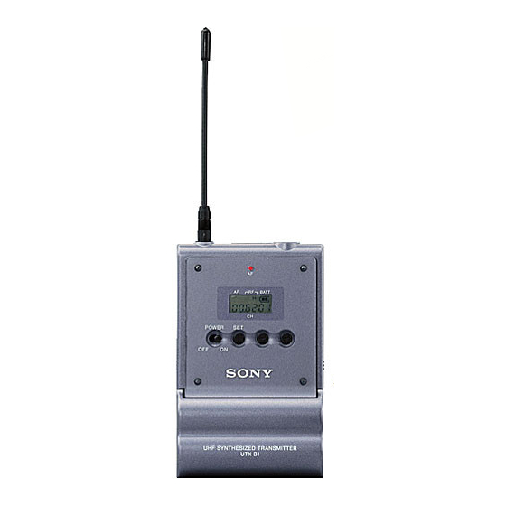
To prevent electromagnetic interference from portable Identification communication devices The use of portable telephones and other communication devices near the UWP-X5 products may result in malfunction and interference with audio signals. It is recommended that Body-pack transmitter portable communication devices near (UTX-B1) the UWP-X5 products be turned off. - Page 7 d Display section Transmission channel BATT Transmission Press frequency Attenuation button. level of the input signal A AF (audio frequency) indication Accumulated Appears whenever the input audio signal is battery use time stronger than the reference level. B RF (radio frequency) indication e + (+ selection) / –...
-
Page 8: Diversity Tuner Module (Urx-M1)
SET button, the channel indication changes Diversity tuner module as follows. (URX-M1) For details, see“Settings” on page 15. Reception channel group Press and number Reception button. frequency d + (+ selection) / – (– selection/reset) a SET button buttons Press to change display parameters. Press these buttons to set the reception For details, see “Settings”... -
Page 9: Power Supply
a Ear clip Power Supply b Case c Microphone cable This section explains the power supply for d Headband (supplied) each component. e Connector (mini phono plug with a lock mechanism) Diversity tuner module (URX- f Clip (supplied) When incorporated into another component g Boom (e.g., MB-X6, SRP-X500P, etc.), the tuner module draws its power from that... -
Page 10: Battery Indication
If there seems to be poor battery Be sure to check the expiration date printed contact, consult your Sony dealer. on the new batteries before using them. BATT Battery status... -
Page 11: Attachment And Installation Procedures
To wear the head-set type Attachment and microphone Installation The head-set type microphone can be worn on either ear. Procedures This section describes the procedures for attaching the supplied accessories to the body-pack transmitter (UTX-B1) and the installation of the diversity tuner module Hook the upper part of the ear clip on an (URX-M1) into the MB-X6 Tuner Base ear, then press the ear clip gently onto the... - Page 12 To attach the headband and To attach the belt clip clip The headband can be attached on either side. To wear the microphone more securely, attach the supplied headband (1) before wearing the microphone. To prevent the microphone from falling off, attach the supplied clip (2) to the microphone cable, then clip the microphone cable to the clothing.
-
Page 13: Installing A Diversity Tuner Module (Urx-M1)
Installing a diversity tuner module (URX-M1) Notes • Before installing the diversity tuner module (URX-M1), make sure the unit When installing the tuner unit into the into which the tuner module will be tuner slot other than slot 1, push the installed is turned off. - Page 14 Tuner module To remove a diversity tuner module After removing the front cover, hold the tuner unit by the top and bottom, then pull it out of the slot. To remove the diversity tuner module Pull the latch securing the tuner module to the side and pull out the tuner module.
-
Page 15: Settings
Notes Settings • When you are setting the transmission channel, the transmitter cannot be used to transmit signals. • Do not remove the batteries while setting Setting the transmission the transmission channel. If they are inadvertently removed, re-insert them channel (UTX-B1 only) immediately and redo the procedure See “Wireless microphone system frequency list”... - Page 16 Pressing the + button cycles the number stops flashing and the indication in the order shown in the selection is stored in memory. tables in “Wireless microphone system frequency list” on page 26. To select the channel by Pressing the – button cycles the frequency indication indications in the opposite direction.
-
Page 17: Detecting And Selecting The Available Channels Automatically (Urx-M1 Only)
the reception channel, the unit may not • Do the automatic detection and selection operate normally. Wait a few seconds of available channels with the channel before turning it on again. group other than channel group 00. • When there are unavailable channels due to extraneous radio wave and the channel Detecting and selecting the could not be selected on some tuner... -
Page 18: Resetting The Accumulated Battery Use Time Indication (Utx-B1 Only)
Do the following while there Set the POWER switch to OFF to complete the setting, or press the SET is no signal transmission. button to set other items. Set the POWER switch to OFF to The results are stored in memory. complete the setting, or press the SET The change becomes effective the next button to set other items. -
Page 19: Operation
• Do not use two or more transmitters with page 20. the same wireless channels. Set the transmission channel on the • When operating two or more UWP-X5’s transmitter, and then turn off the unit. simultaneously, set each package to a different channel within the same For details on setting the transmission channel group. -
Page 20: System Configuration
Note Production of the peripheral and relating devices may have been discontinued. Upon selecting the devices to be used with this product, consult your nearest Sony representative or the dealer from whom you purchased the product. Sample configurations for AV presentations... -
Page 21: Error Messages
Contact your Sony dealer. memory data. Err 02 The PLL synthesized circuit is Restart the unit. If the message abnormal. appears again, contact your Sony dealer. Err 03* The battery voltage exceeds the Use the specified battery. allowable limit. * Body-pack transmitter (UTX-B1) only... -
Page 22: Troubleshooting
Troubleshooting If you have any problem using the UWP-X5, use the following checklist. Should any problem persist, consult your Sony dealer. Symptom Meanings Remedy The unit does The polarity orientation of the Insert the batteries with the correct not turn on.* batteries in the battery polarity orientation. - Page 23 Symptom Meanings Remedy There is The attenuation level of the The input level of the tuner is distortion in transmitter is too low. extremely high. Press the – button the sound. on the transmitter in attenuation level setting mode to raise the attenuation level.
-
Page 24: Specifications
3.0 V DC (two LR6/AA size Mass Approx. 140 g (5 oz) including alkaline batteries) batteries Battery life Approx. 6 hours (measured with two Sony LR6/AA size alkaline Tuner (URX-M1) batteries at 25°C (77°F), with Type of reception output power of 10 mW) Space diversity... - Page 25 ±5 kHz Note Frequency characteristics Always verify that the unit is operating 50 Hz to 18 kHz properly before use. SONY WILL NOT Distortion BE LIABLE FOR DAMAGES OF ANY 1.0% or less at 1 kHz modulation KIND INCLUDING, BUT NOT...
-
Page 26: Appendix
Guidance on the use of a multi-channel system When building up a multi-channel system, Sony recommends that one of the groups listed under "Groups for the tuner" is selected to avoid mutual interference from other Sony wireless microphones/transmitters. Group for transmitter and tuner... - Page 27 TV-69 69-01 800.125 69-13 801.625 69-25 803.125 69-37 804.625 69-02 800.250 69-14 801.750 69-26 803.250 69-38 804.750 69-03 800.375 69-15 801.875 69-27 803.375 69-39 804.875 69-04 800.500 69-16 802.000 69-28 803.500 69-40 805.000 69-05 800.625 69-17 802.125 69-29 803.625 69-41 805.125 69-06 800.750...
- Page 28 Group H2 Grouping 7 channels. Grouping 7 channels. 69-09 801.125 69-10 801.250 69-11 801.375 69-13 801.625 69-19 802.375 69-17 802.125 69-25 803.125 69-22 802.750 69-30 803.750 69-28 803.500 69-34 804.250 69-36 804.500 69-37 804.625 69-38 804.750 Sony Corporation Printed in Korea...