Sony UWP-D21 Operating Instructions Manual
Hide thumbs
Also See for UWP-D21:
- Operating instructions manual (41 pages) ,
- Quick start manual (2 pages)
Table of Contents
Advertisement
5-042-114-11 (1)
UHF Wireless Microphone Package
UHF Synthesized Transmitter
UHF Synthesized Wireless Microphone
UHF Synthesized Diversity Tuner
Operating Instructions
Before operating the unit, please read this manual thoroughly
and retain it for future reference.
UWP-D21/D22/D26/D27
UTX-B40
UTX-M40
UTX-P40
URX-P40
URX-P41D
© 2022 Sony Corporation
Advertisement
Table of Contents

Related Manuals for Sony UWP-D21


Summary of Contents for Sony UWP-D21
- Page 1 UHF Wireless Microphone Package UHF Synthesized Transmitter UHF Synthesized Wireless Microphone UHF Synthesized Diversity Tuner Operating Instructions Before operating the unit, please read this manual thoroughly and retain it for future reference. UWP-D21/D22/D26/D27 UTX-B40 UTX-M40 UTX-P40 URX-P40 URX-P41D © 2022 Sony Corporation...
-
Page 2: Table Of Contents
Transmitter Settings ......... 39 Menu structure and operation ..... 39 Setting the transmit channel......40 Configuration of the Packages ....3 Configuration menu ........41 UWP-D21 ............. 3 System Configuration Example ....45 UWP-D22 ............. 4 Error Messages .........46 UWP-D26 ............. 5 Troubleshooting ........ -
Page 3: Configuration Of The Packages
Configuration of the Packages This manual is for the UWP-D21/D22/D26/D27 Wireless Microphone Packages. The contents of each package are described below. Note Some of the packages may not be available in certain countries or areas. In addition, the U90 model can only be used in the USA. -
Page 4: Uwp-D22
UWP-D22 The package consists of a hand-held microphone (UTX-M40), a portable diversity tuner (URX-P40), and their accessories. When used in conjunction with a compact camcorder, a mobile system for ENG (Electronic News Gathering) or EFP (Electronic Field Production) applications can be constructed. Portable diversity tuner Hand-held microphone (URX-P40) (1) -
Page 5: Uwp-D26
UWP-D26 The UWP-D26 consists of a plug-on transmitter (UTX-P40), a body-pack transmitter (UTX-B40), a portable diversity tuner (URX-P40), and their accessories. When used in conjunction with a compact camcorder, a mobile system for ENG (Electronic News Gathering) or EFP (Electronic Field Production) applications can be constructed. Plug-on transmitter Body-pack transmitter Portable diversity tuner... -
Page 6: Uwp-D27
UWP-D27 The package consists of two body-pack transmitters (UTX-B40), a portable diversity tuner (URX-P41D) that can receive two frequencies, and their accessories. When used in conjunction with a compact camcorder, a mobile system for ENG (Electronic News Gathering) or EFP (Electronic Field Production) applications can be constructed. Body-pack transmitter Portable diversity tuner (UTX-B40) (2) -
Page 7: Models Available Separately
Models available separately The transmitter and tuner in each package are available for purchase separately. The components provided with each product are given below. UTX-B40 • Body-pack transmitter (UTX-B40) (1) • Omni-directional lavalier microphone (1) • Wind screen (1) • Holder clip (1) •... -
Page 8: Features
URX-P41D)). In combination with a compact camcorder or interchangeable-lens digital camera, the packages can • High quality sound with Sony Digital Audio Processing be used for various purposes, such as ENG (Electronic • “NFC SYNC” function for quick and easy secure... -
Page 9: Name And Function Of Parts
• USB for power supply • Digital audio interface support using SMAD-P5 multi- interface shoe-mount adaptor (option)* * For details on cameras that support this function, visit the Sony website. a Antenna b POWER indicator Displays the battery level. Indicator display... - Page 10 • If a lavalier microphone other than the one supplied is For details, see “Configuration menu” (page 41). connected, the proper performance may not be obtained. I Gain mode indicator Displays the gain mode setting. e Display section For details, see “Setting the audio gain (GAIN MODE)” (page 41).
-
Page 11: Hand-Held Microphone (Utx-M40)
You can disable the power supply operation of the Hand-held microphone (UTX-M40) POWER/MUTE button and change the muting function on/off control method from the configuration menu. For details, see “Setting the operation of the audio muting function (POWER/MUTE) (UTX-M40 only)” (page 42). -
Page 12: Plug-On Transmitter (Utx-P40)
For details about the muting function, see “Setting the Plug-on transmitter (UTX-P40) operation of the audio muting function (POWER/MUTE) (UTX-M40 only)” (page 42). Front F Battery level indicator Displays the battery level. For details, see “Battery level indicator” (page 19). G Menu display section Displays various functions. - Page 13 e Display section I Gain mode indicator Displays the gain mode setting. For details, see “Setting the audio gain (GAIN MODE)” (page 41). f + or – button Selects functions or values shown on the display. g Infrared detector Receives the frequency and compander mode set on the tuner.
-
Page 14: Portable Diversity Tuner (Urx-P40)
a Antenna Portable diversity tuner (URX-P40) b PHONES (monitor) connector (3.5-mm Front diameter, stereo mini jack) Connect to headphones to monitor the audio output. Note Do not connect headphones with a monaural mini jack. This may short-circuit the headphone outputs, resulting in distorted sound output. - Page 15 j SET button B Peak indicator Lights up when the signal is 3 dB below the level at which Adjusts displayed function settings and enters the distortion begins as a warning of excessive input level. displayed value. Holding down the SET button while turning on the power turns the transmitter on without transmitting a signal C Transmitter power warning indicator (transmission stopped mode).
-
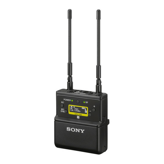
Page 16: Portable Diversity Tuner (Urx-P41D)
a Antenna Portable diversity tuner (URX-P41D) b POWER indicator Front Displays the battery level. Indicator display Status On (green) Sufficient battery level Flashing (green) Battery is getting low Supply OFF c RF (radio frequency input) indicators Lights up as shown below depending on the RF input level of tuner 1 and tuner 2. - Page 17 SMAD-P5 Connect to plug-in power type external microphones and (not supplied). Sony BMP type lavalier microphones For details, see “Battery level indicator” (page 19). o POWER switches Turns tuner 1 and tuner 2 on/off.
-
Page 18: Power Supply
Body-pack transmitter (UTX-B40) / Power Supply portable diversity tuner (URX-P40/P41D) The following describes the procedure using illustrations for the body-pack transmitter (UTX-B40). Batteries can This section describes the power supply of each device. be inserted in the portable diversity tuner (URX-P40/ P41D) in the same manner. - Page 19 Locked Unlocked Hand-held microphone (UTX-M40) Insert two new AA batteries into the battery Press and hold the POWER/MUTE button or compartment with 3 and # polarities in the correct POWER button to turn the power off. orientation. Note The button used to turn off power varies depending on the POWER/MUTE setting.
-
Page 20: Supplying Power From A Usb Connector
• Battery power is gradually consumed, even when the operate with cameras equipped with a multi-interface shoe, such as Sony video camera recorders and digital unit is turned off. Remove the batteries from the unit cameras that use an interchangeable lens, by connecting before prolonged periods of disuse. -
Page 21: Attaching Accessories
Attaching the wind screen to the Attaching Accessories microphone This section describes how to attach the supplied accessories to each device. Align and insert the microphone Attaching accessories to the into the hole in the wind screen. body-pack transmitter (UTX-B40) Attaching a belt clip Connecting the microphone Microphone (supplied) -
Page 22: Attaching Accessories To The Hand-Held Microphone (Utx-M40)
Disconnecting a microphone or cable Attaching accessories to the hand-held microphone (UTX-M40) Microphone or cable connector Attaching the microphone holder Release button Press the release button firmly until the lock is fully released, and pull the microphone or cable out slowly. Insert the base of the microphone into the holder. -
Page 23: Operation
Operation Procedure for all transmitters (UTX-B40/M40/ P40) and portable diversity tuner (URX-P40) Connect the tuner as required. For details about example connections, see “System Configuration Example” (page 45). Press and hold the POWER button for at least one second on the tuner to turn the power on. Note Some noise may occur when power is turned on. - Page 24 Information about the channel set on the tuner is sent groups on tuners 1 and 2, turn on only one of the to the transmitter, and then the transmit channel is set. tuners at a time and press the NFC SYNC button to “COMPLETE”...
-
Page 25: If Noise Is Generated
Information about the channel and compander mode Note set on the tuner are sent to the transmitter, and then • When SYNC MODE is set to NFC, infrared the transmit channel is set. communication is not possible. “COMPLETE” is shown on the display of the For details about how to set SYNC MODE, see transmitter and tuner, and the transmitter vibrates “Configuring using communication with the... -
Page 26: Tuner Settings
• VERSION (software version) display Tuner Settings Basic menu operation The basic menu operation is the same in simple mode and advanced mode. Menu structure and operation Procedure for portable diversity tuner (URX-P40) Function name There are two menu display modes that can be selected according to the application. -
Page 27: Setting The Receive Channel
Menu tree Basic menu operation MENU <UTILITY> Menu name Meter screen PHONES Function name OUTPUT LEVEL OUTPUT MODE RUNNING TIME MONITOR MODE POWER SOURCE SYNC MODE SCAN TYPE BATTERY TYPE Setting DISPLAY MODE BRIGHTNESS Press the MENU button and select the menu to set or FCT RESET change. -
Page 28: Searching For Available Channels Within A Group (Clear Channel Scan)
Press the + or – button to select the desired group flashing, the displayed setting that is flashing is saved. name, then press the SET button. The same applies when setting other parameters. • The frequency indicator changes in response to the The channel group is set, and the channel number channel number. -
Page 29: Searching For Active Channels Within A Group (Active Channel Scan)
Select YES, and place the N-Marks of the transmitter Press the SET button when the desired channel and tuner in close proximity. number starts flashing. Information about the channel set on the tuner is sent The search for available channels finishes and the to the transmitter, and then the transmit channel is set. -
Page 30: Adjusting The Monitor Audio Level
Press and hold the SET button for one second or To cancel searching Press the – button. The display returns to the ACT CH longer. SCAN screen. Press and hold until the channel group and “+” display starts flashing. Press the SET button when the desired channel number starts flashing. -
Page 31: Configuration Menu
Press the + or – button to set the desired monitor For details about adjusting the monitor audio level, see audio level, then press the SET button. “Adjusting the monitor audio level” (page 30). The setting is saved and retained even after the power Configuring transmitter settings via NFC is turned off. - Page 32 The frequency and compander mode for use on the Setting the menu display mode (MENU tuner are set. MODE) Sets the menu display mode. Notes SIMPLE: Displays only the required settings. • NFC communication lasts approximately 20 seconds. ADVANCED: Displays all settings. Perform step 4 within 20 seconds of performing step 3.
- Page 33 Press the + or – button to display “YES,” and press combination with UWP-D series devices. the SET button. UWP: Mode supported in combination with Sony UWP-series transmitters. The display returns to the CH MEMORY menu. WL800: Mode supported in combination with Sony 800-series transmitters.
-
Page 34: Utility Menu
(Dark) 1 2 3 4 5 6 7 8 9 10 (Bright) For details about adjusting the monitor audio level, see “Adjusting the monitor audio level” (page 30). Note This function is displayed in advanced mode only. Setting the audio output range (OUTPUT MODE) Restoring factory default settings (FCT Sets the audio output range of the OUTPUT 1/2 (audio... - Page 35 To release monitor audio level mode Communication method Tuner for configuration on Press and hold the SET button, MENU button, or URX-P41D each transmitter NFC SYNC button for one second or longer until Infrared “ESCAPE?” is displayed. communication communication UTX-B40 Press the + or –...
-
Page 36: Rx1/2 (Tuner 1/2) Menu
Changing the display settings (DISPLAY Note MODE) This menu is not available on the Japan model, Korea Changes the display mode of the OLED display when 30 model, 90U model, and E model. On these models, the seconds have elapsed without any button activity. frequency band cannot be selected. - Page 37 • NFC communication lasts approximately 20 The frequency and compander mode for use on the seconds. Perform step 6 within 20 seconds of tuner are set. performing step 5. If more than 20 seconds have Notes elapsed, a confirmation display appears prompting whether to start NFC communication.
-
Page 38: Ext.in Menu
SET button. Tuner 2 OUTPUT2 RX2: OUT2 The selected compander mode is set. UWP-D: Select for combination with Sony UWP-D- series transmitters. EXT.IN menu UWP: Select for combination with Sony UWP-series transmitters. Procedure for portable diversity tuner... -
Page 39: Transmitter Settings
OFF: Select when not using an external microphone. Transmitter Settings PLUG-IN PWR: Select when using an plug-in power type microphone. MONO BMP+5V: Select when using a Sony lavalier microphone. Menu structure and operation Adjusting the input level (INPUT LEVEL) Procedure for all transmitters (UTX-B40/M40/ You can set the input level in the range –12 dB to +12 dB. -
Page 40: Setting The Transmit Channel
• RF POWER (RF transmit output level) select • +48V SUPPLY (+48 V power supply) setting Function name (UTX-P40 only) • POWER LOCK (POWER button lock) function • RUNNING TIME (accumulated running time) display • MENU MODE (menu display mode) setting •... -
Page 41: Configuration Menu
For details about the groups and channels in each frequency band, refer to the “Frequency List”. Adjusting the audio input attenuation level (ATTENUATOR) You can set the audio input attenuation level in 3 dB increments to reduce noise distortion. Press the + or – button to select the desired channel The factory default setting is 9 dB on the UTX-B40, and number, then press the SET button. - Page 42 If an excessive audio level is input, it may cause noise The factory default setting is 00:00. Up to 99:59 can be distortion or damage the playback/recording displayed. equipment. To reset the time display • “---” is displayed for ATTENUATOR and GAIN MODE if INPUT LEVEL is set to LINE, and the Press and hold the SET button until the time display settings cannot be modified.
- Page 43 Note UWP-D: High speech quality mode supported in This function is displayed in advanced mode only. combination with UWP-D series devices. UWP: Mode supported in combination with Sony Setting the display brightness UWP-series tuners. (BRIGHTNESS) WL800: Mode supported in combination with Sony 800-series tuners.
- Page 44 Displaying the software version (VERSION) Displays the software version of the transmitter. Note This function is displayed in advanced mode only.
-
Page 45: System Configuration Example
System Configuration Example The following is a configuration example for use with UWP-D series devices. Sample configuration for ENG (Electronic News Gathering) or EFP (Electronic Field Production) with a camcorder For URX-P40 portable diversity tuner Portable diversity tuner (URX-P40) (with shoe mount adaptor attached or XLR-BMP cable connection) Plug-on transmitter Hand-held... -
Page 46: Error Messages
Meaning Solution EEP ERROR An error has occurred in the backup memory data. Contact your point of purchase or Sony service representative. PLL ERROR An error occurred in the PLL synthesizer circuit. Restart the unit. If the message persists, contact your point of purchase or Sony service representative. -
Page 47: Troubleshooting
Troubleshooting If you have any problem, use the following checklist before asking for repairs. If the problem persists, contact your point of purchase or Sony service representative. Symptom Cause Solution The unit does not turn The 3 and # polarity orientation of the batteries is Insert the batteries with the correct polarity incorrect. - Page 48 Symptom Cause Solution There is no sound. The channel setting on the transmitter is different Use the same channel setting on both the from that on the tuner. transmitter and tuner. The transmitter is not transmitting signals, or the Confirm that the transmitter is turned on. transmission output is weak.
- Page 49 Symptom Cause Solution There is sound The channel setting on the transmitter is different Use the same channel setting on both the interruption or noise. from that on the tuner. transmitter and tuner. Two or more transmitters are set to the same Two or more transmitters cannot be used on the channel.
- Page 50 Symptom Cause Solution The transmitter The N-Marks of both units are not facing each Place the N-Marks approximately 5 mm from each channel cannot be set other, or they are too far apart. Or there may be other. Make sure there are no metallic or other via NFC some metallic object between the N-Marks.
-
Page 51: Important Notes On Use
• To avoid degradation of the signal to noise ratio, do not ANY OTHER REASON WHATSOEVER. use UWP-D devices in noisy places or in locations • SONY WILL NOT BE LIABLE FOR CLAIMS OF subject to vibration, such as the following: ANY KIND MADE BY USERS OF THIS UNIT OR –... -
Page 52: Specifications
Tone signal frequency Specifications In UWP-D compander mode: 32.382 kHz In UWP compander mode: 32 kHz In WL800 compander mode: The N-Mark is a trademark or registered trademark of 32.768 kHz NFC Forum, Inc. in the United States and in other Supply voltage DC 3.0 V (two LR6/AA size alkaline countries. - Page 53 Dimensions Battery life (measured with two LR6/AA size alkaline batteries at 25 °C (77 °F), DISPLAY MODE set to AUTO OFF) Approx. 8 hours with output power of 30 mW (UC, U, CE, LA, CN models) Approx. 10 hours with output power of 10 mW (E, KR models) Dimensions ø48 (1...
-
Page 54: Tuner (Urx-P40/P41D)
Approx. 7 hours with output power of 42LA model: 638.125 MHz to 10 mW (E, KR models) 697.875 MHz Dimensions (UHF-TV channels 42 to 51) 29CN model: 638.025 MHz to 694.000 MHz (UHF-TV channels 29 to 35) KR model: 925.125 MHz to 937.375 MHz E model: 794.125 MHz to 805.875 MHz Signal-to-noise ratio... - Page 55 Battery life Approx. 6 hours (measured with two Dimensions LR6/AA size alkaline batteries at 25 °C (77 °F), DISPLAY MODE set to AUTO OFF) Dimensions 63 (2 35 (1 63 × 70 × 35 mm (2 × 2 × 1 in.) (width/height/depth) 63 (2...
- Page 56 Sony Corporation...