Advertisement
Table of Contents
- 1 Table of Contents
- 2 Connection of Peripheral Devices
- 3 Installation Method
- 4 Specifications of Wiring and Terminals
- 5 Operation/Control
- 6 Adjustment of the Frequency Setting Potentiometer and Indicator
- 7 Function List
- 8 Errors and Protective Functions
- 9 Specifications
- 10 Outline Drawings
- 11 Appendix 1 Instructions for Compliance with the European
- 12 Appendix 2 Instructions for Compliance with U.S. and Canadian
- Download this manual
TRANSISTORIZED INVERTER
FR-
S
500
INSTRUCTION MANUAL (BASIC)
FR-S520-0.1K to 3.7K(-R)(-C)
FR-S520-0.1K to 3.7K-NA(R)
FR-S520S-0.1K to 1.5K(-R)
FR-S520S-0.2K to 1.5K-EC(R)
Thank you for choosing this Mitsubishi Transistorized inverter.
If this is the first time for you to use the FR-S500 series, please read through
this instruction manual (basic) carefully and use the inverter safely.
If you are going to use the inverter for higher-level applications, the FR-S500
instruction manual (detailed) [IB(NA)-0600027] is separately available from
where you purchased the inverter or your Mitsubishi sales representative.
1. CONNECTION OF PERIPHERAL DEVICES ......................................2
2. INSTALLATION METHOD ..................................................................4
3. SPECIFICATIONS OF WIRING AND TERMINALS ............................5
4. OPERATION/CONTROL...................................................................15
POTENTIOMETER AND INDICATOR ..............................................21
6. FUNCTION LIST ...............................................................................25
7. ERRORS AND PROTECTIVE FUNCTIONS .....................................37
8. SPECIFICATIONS.............................................................................40
9. OUTLINE DRAWINGS ......................................................................44
CONTENTS
Standards ...........................................................................46
Electrical Codes..................................................................48
Advertisement
Table of Contents

Related Manuals for Mitsubishi FR-S520-0.1K to 3.7K(-R)(-C)


Summary of Contents for Mitsubishi FR-S520-0.1K to 3.7K(-R)(-C)
-
Page 1: Table Of Contents
(basic) carefully and use the inverter safely. If you are going to use the inverter for higher-level applications, the FR-S500 instruction manual (detailed) [IB(NA)-0600027] is separately available from where you purchased the inverter or your Mitsubishi sales representative. CONTENTS 1. CONNECTION OF PERIPHERAL DEVICES ........2 2. - Page 2 This instruction manual (basic) provides handling information and precautions for use of the equipment. Please forward this instruction manual (basic) to the end user. This instruction manual uses the International System of Units (SI). The measuring units in the yard and pound system are indicated in parentheses as reference values.
- Page 3 2. Fire Prevention CAUTION ! Mount the inverter to incombustible material. Mounting it to or near combustible material can cause a fire. ! If the inverter has become faulty, switch off the inverter power. A continuous flow of large current could cause a fire. ! Do not connect a resistor directly to the DC terminals P(+), N(−).
- Page 4 CAUTION ! Use the inverter under the following environmental conditions: Ambient -10°C to + 50°C (14°F to 122°F) (non-freezing) temperature Ambient humidity 90%RH or less (non-condensing) Storage -20°C to +65°C (-4°F to 149°F) * temperature Indoors (free from corrosive gas, flammable gas, Ambience oil mist, dust and dirt) Maximum 1000m (3280.80feet) above sea level...
- Page 5 CAUTION ! The electronic overcurrent protection does not guarantee protection of the motor from overheating. ! Do not use a magnetic contactor on the inverter input for frequent starting/stopping of the inverter. ! Use a noise filter to reduce the effect of electromagnetic interference. Otherwise nearby electronic equipment may be affected.
- Page 6 Japanese Power Supply Harmonic Suppression Guideline The "harmonic suppression guideline for household appliances and general- purpose products" issued by the Ministry of International Trade and Industry in September, 1994 applies to the FR-S500 series. By installing the FR-BEL or FR- BAL power factor improving reactor, this product complies with the "harmonic suppression techniques for transistorized inverters (input current 20A or less)"...
-
Page 7: Connection Of Peripheral Devices
< Type with RS-485 communication function > When using the RS-485 connector to wire the cable, you can cut off the lug of the wiring cover to wire it. (Cutting off the lug provides protective structure IP10.) CAUTION The connector above the operation panel is for manufacturer use. - Page 8 Selection of peripheral devices (Selection changes with the power supply input specifications of the inverter.) FR-S520-0.1K to 3.7K(-R)(-C) FR-S520-0.1K to 3.7K-NA(R) No-Fuse Cables (mm Breaker (*2) Power Power Motor (NFB*1) or Factor Factor Magnetic Output Inverter Earth Improving Improving Contactor Leakage Type (MC)
-
Page 9: Installation Method
INSTALLATION METHOD 2.1 Installation of the Inverter Enclosure surface mounting Mounting inside enclosure Fix the front cover and wiring cover after removing them. When containing two or more inverters, install them in parallel Leave enough clearances and provide cooling measures. and provide cooling measures. -
Page 10: Specifications Of Wiring And Terminals
SPECIFICATIONS OF WIRING AND TERMINALS 3.1 Terminal connection diagram (Japanese version) FR-S520-0.1K to 3.7K (-R) (-C) Inverter Motor 3-phase AC power supply Ground External transistor common 24VDC power supply Power factor improving Contact input common (source) DC reactor (FR-BEL: Option) Take care not to short Jumper: Remove this terminals PC-SD. - Page 11 FR-S520S-0.1K to 1.5K (-R) (-C) Motor Power supply Earth (Ground) Remarks • To ensure safety, connect the power input to the inverter via a magnetic contactor and earth leakage circuit breaker or no-fuse breaker, and use the magnetic contactor to switch power on-off. •...
- Page 12 3.1.1 Layout and wiring of main circuit terminals FR-S520-0.1K, 0.2K, 0.4K, 0.75K (-R) (-C) FR-S520-1.5K, 2.2K, 3.7K (-R) (-C) Jumper Jumper Power Motor supply Power Motor supply FR-S520S-0.1K, 0.2K, 0.4K, 0.75K (-R) FR-S520S-1.5K (-R) Jumper Jumper Power Motor supply Power Motor supply Screw size: M3.5...
- Page 13 3.2 Terminal connection diagram (North America version) FR-S520-0.1K to 3.7K-NA (R) Inverter Motor 3-phase AC power supply Earth (Ground) External transistor common 24VDC power supply Power factor improving Contact input common (source) DC reactor (FR-BEL: Option) Take care not to short Jumper: Remove this terminals PC-SD.
- Page 14 3.2.1 Layout and wiring of main circuit terminals FR-S520-0.1K, 0.2K, 0.4K, 0.75K-NA (R) FR-S520-1.5K, 2.2K, 3.7K-NA (R) Jumper Jumper Power Motor supply Power Motor supply Screw size: M3.5 Screw size: M4 Recommended cable size: Recommended cable size: (14 AWG) (14 AWG) (1.5K, 2.2K) Crimping terminal: 2-3.5 3.5mm (12 AWG) (3.7K)
- Page 15 3.3 Terminal connection diagram (European version) FR-S520S-0.2K to 1.5K-EC (R) Inverter Motor Power supply Earth (Ground) External transistor common 24VDC power supply Power factor improving Contact input common (source) DC reactor (FR-BEL: Option) Take care not to short Jumper: Remove this terminals PC-SD.
- Page 16 3.3.1 Layout and wiring of main circuit terminals FR-S520S-0.2K, 0.4K, 0.75K-EC (R) Jumper Power Motor supply Screw size: M3.5 Recommended cable size: 2mm (14 AWG) Crimping terminal: 2-3.5 Screw tightening torque: 1.2 N⋅m Overall wiring length: 100m (328.08feet) maximum * CAUTION If the wiring length of the 0.2K is 30m (98.43feet) or more, reduce the carrier frequency to 1kHz.
- Page 17 3.4 Main Circuit 3.4.1 Explanation of main circuit terminals Symbol Terminal Name Description R, S, T* AC power input Connect to the commercial power supply. U, V, W Inverter output Connect a three-phase squirrel-cage motor. DC voltage DC voltage common terminal. Not isolated from the power N <->...
- Page 18 Symbol Terminal Name Description Common terminal for the frequency setting signals (terminals 2, 4) and indicator connection (terminal AM). Frequency Isolated from terminals SD and SE. Do not connect this setting input terminal to the ground. common 1 contact output which indicates that the The terminal protective function of the inverter is function...
- Page 19 3.5.2 Arrangement and wiring of control circuit terminals PC SE ..Japanese version SD STF STR RL RM RH <AM> ..NA, EC version Loosen the terminal screw and insert the cable into the terminal. Screw size: M3 (A, B, C terminals), M2 (other than on the left) Tightening torque: 0.5N⋅m to 0.6N⋅m (A, B, C Cable stripping size terminals)
-
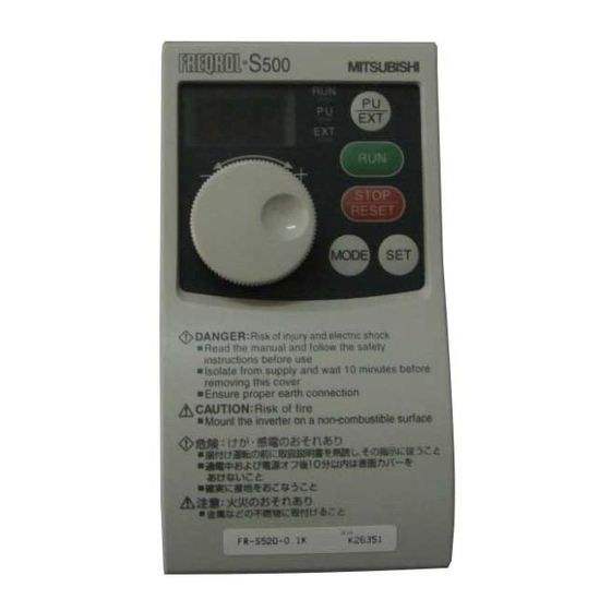
Page 20: Operation/Control
OPERATION/CONTROL <Control panel> The operation panel cannot be removed from the inverter. RUN indication PU/EXT key Turns on/flickers* to indicate operation. Used to switch between the PU and external operation PU indication mode. (Change the Pr. 79 Lit to indicate the PU value to use the combined operation mode. - Page 21 4.1 Setting the Frequency to Perform Operation (Example: Performing Operation at 30Hz) Display Operation Screen at power-on The monitor display appears. Press the PU indication is lit. to choose the PU operation mode. Turn the setting dial to show Flickers for the frequency you want to set.
- Page 22 4.2 Setting the Parameters 4.2.1 Example: Changing the Pr. 7 setting from "5s" to "10s" (For parameter details, refer to the instruction manual (detailed).) Display Operation Confirm the RUN indication and operation mode indication. The inverter must be at a stop. The inverter must be in the PU operation mode.
- Page 23 4.2.2 Example: Changing the Pr. 30 setting from "0" to "1" (The extended parameters are made valid by setting "1" in Pr. 30 "extended function display selection". Refer to page 27 for the extended function parameter list and to the instruction manual (detailed) for details.) Display Operation Confirm the RUN indication and operation...
- Page 24 4.3 Clearing the Parameters POINT • The clear parameter CLr is an extended parameter. Set "1" in Pr. 30 and turn the dial to show it. (Refer to page 18.) • The parameters can be cleared by setting "1" in CLr "parameter clear". Display Operation Confirm the RUN indication and operation...
- Page 25 4.4 Monitoring the Output Current POINT The output current appears while the key is pressed in the monitor mode. Display Operation Press the key to choose the output MODE frequency monitor mode. Independently of whether the (1.0A) inverter is running in any operation mode or at a stop, Hold down the output current appears...
-
Page 26: Adjustment Of The Frequency Setting Potentiometer And Indicator
ADJUSTMENT OF THE FREQUENCY SETTING POTENTIOMETER AND INDICATOR • Related parameters Factory Setting Parameter Name Setting Range <EC Version> Frequency setting voltage gain frequency 1 to 120Hz 60Hz <50Hz> Frequency setting current gain frequency 1 to 120Hz 60Hz <50Hz> Frequency setting voltage bias frequency 0 to 60Hz Frequency setting voltage bias 0 to 300%... - Page 27 2) Adjusting the deviation of the highest frequency from the Pr. 38 (Pr. 39) setting. 2)-1 Make adjustment with a voltage applied directly across terminals 2-5 (with a current flowing across terminals 4-5) 2)-2 Make adjustment at any point without a voltage applied across terminals 2- 5 (without a current flowing across terminals 4-5) (For the setting method, refer to the instruction manual (detailed).) Changing example When you want to use the 0 to 5VDC input frequency setting...
- Page 28 Changing example Changing the calibration parameter C4 "frequency setting voltage gain" POINT The calibration parameter C4 is an extended function parameter. Pr. 30 must be set to "1". 2) Adjusting a deviation of the highest frequency from the Pr. 38 (Pr. 39) setting. 2)-1 Making adjustment with a voltage applied directly across terminals 2-5 (with a current flowing across terminals 4-5) Display...
- Page 29 5.2 Adjustment (Calibration) of the Frequency Meter (Indicator) Changing example Deflecting the meter (Analog indicator) to full-scale (Across FM-SD: 1mA, across AM-5: 5V) at 60Hz POINT • The calibration parameters "C1" can be made to be read by setting "1" (extended function parameter valid) in Pr.
-
Page 30: Function List
FUNCTION LIST 6.1 Basic Function Parameter List Minimum Factory Indica- Setting Customer rame- Name Setting Setting tion Range Setting Increments <EC Version> Torque boost 0 to 15% 0.1% Maximum frequency 0 to 120Hz 0.1Hz 60Hz <50Hz> Minimum frequency 0 to 120Hz 0.1Hz Base frequency 0 to 120Hz... - Page 31 Pr. 4 "multi-speed setting (high speed)" Pr. 3 "base frequency" • Set the base frequency (reference Pr. 5 "multi-speed setting (middle speed)" Pr. 6 "multi-speed setting (low speed)" frequency at rated motor torque) • You can select any speed (RH, RM, within the range 0 to 120Hz according to the motor.
- Page 32 6.3 EXTENDED FUNCTION PARAMETER LIST Setting "1" in Pr. 30 "extended function display selection" makes the extended function parameters valid. (Refer to the separately available instruction manual (detailed).) Parameter Factory Setting Indica- Name Outline <EC tion Version> For parameters 0 to 9, refer to the basic function parameters. DC injection brake Set the timing of switching to DC injection operation frequency...
- Page 33 Parameter Factory Setting Name Outline Indica- <EC tion Version> Stall prevention is a function designed to suspend a frequency increase during Stall prevention acceleration or suspend a frequency decrease function selection during deceleration if the preset current (0 to 200%) is exceeded, in order to prevent an overcurrent alarm.
- Page 34 Parameter Factory Setting Name Outline Indica- <EC tion Version> You can set as desired the magnitude (slope) of Frequency setting the output frequency to the external frequency 60Hz voltage gain setting voltage signal (0 to 5V or 0 to 10V). <50Hz>...
- Page 35 Parameter Factory Setting Name Outline Indica- <EC tion Version> Set the level at which the zero current Zero current detection signal (Y13) is output. detection level 0 to 200% When the output current is at or below the zero current detection level (Pr. 50) for longer than this Zero current period (Pr.
- Page 36 Parameter Factory Name Outline Indica- Setting tion You can choose the following input signals: 0: RL (multiple low-speed operation command) RL terminal function 1: RM (multiple middle-speed operation selection command) 2: RH (multiple high-speed operation command) 3: RT (second function selection) RM terminal 4: AU (current input selection) function selection...
- Page 37 0: Soft-PWM invalid 1: Soft-PWM valid Set the motor to be used. 0: Thermal characteristic for Mitsubishi standard motor Applied motor 1: Thermal characteristic for Mitsubishi constant-torque motor You can change the PWM carrier frequency.
- Page 38 Parameter Factory Name Outline Indica- Setting tion Multi-speed setting Setting other than "- - -" specifies speeds 8 to 15. - - - (speed 8) By combining ON and OFF of the contact signals (RH, RM, RL, REX signals), the running Multi-speed setting - - - speed can be changed step-by-step.
- Page 39 Calibration Parameter Factory Name Outline Indica- Setting tion You can calibrate the indicator connected to FM (AM) terminal across terminals FM-SD (AM-5). (FM:900) calibration (AM:901) You can set as desired the magnitude (slope) Frequency setting of the output frequency to the external voltage bias frequency setting voltage signal (0 to 5V or 0 (902)
- Page 40 • Parameters which can be read on only the type having the RS-485 communication function. (When the parameter unit (FR-PU04) is used, operation from the operation panel is not accepted.) Communi- Factory cation Setting Parameter Name Outline <NA, EC Indica- Version>...
- Page 41 Communi- Factory cation Setting Parameter Name Outline <NA, EC Indica- Version> tion 0: Without CR/LF CR/LF selection 1: With CR, without LF (341) 2: With CR/LF PROM write 0: Write to RAM and E PROM (342) 1: Write to RAM only selection 0: Japanese 1: English...
-
Page 42: Errors And Protective Functions
7. ERRORS AND PROTECTIVE FUNCTIONS 7.1 About Errors (Definitions) When an alarm occurs in the inverter, the protective function is activated to bring the inverter to an alarm stop and the PU display automatically changes to any of the following error (alarm) indications. For details, refer to the instruction manual (detailed) which is separately available. - Page 43 Control Panel Function Name Definition Indication PU was disconnected when communication parameter n17 = "1". PU disconnected (PUE) This function is valid for only the type with RS-485 communication function. Operation could not be resumed properly Retry count (RET) within the preset number of retries. Arithmetic operation of the built-in CPU CPU error (CPU)
- Page 44 (4) Write errors Control Panel Function Name Definition Indication • Write was performed with "1" set in Pr. 77. • Frequency jump setting range overlapped. (Er1) Write disable error • Parameter write was performed though the operation panel does not have the write precedence.
-
Page 45: Specifications
(4.62) *1. The applicable motor capacity indicated is the maximum capacity applicable for use of the Mitsubishi 4-pole standard motor. *2. The rated output capacity indicated assumes that the output voltage is 230V. *3. The % value of the overload capacity indicates the ratio of the overload current to the inverter's rated output current. - Page 46 (3.3) *1. The applicable motor capacity indicated is the maximum capacity applicable for use of the Mitsubishi 4-pole standard motor. *2. The rated output capacity indicated assumes that the output voltage is 230V. *3. The % value of the overload capacity indicates the ratio of the overload current to the inverter's rated output current.
- Page 47 8.2 Common Specifications Selectable between Soft-PWM control and high carrier Control method frequency PWM control, V/F control or automatic torque boost control selectable. Output frequency range 0.5 to 120Hz (starting frequency variable between 0 and 60Hz) 5VDC input: 1/500 of max. set frequency, 10V, 4 to 20mADC Frequency setting input: 1/1000 of max.
- Page 48 -10°C to +50°C (14°F to 122°F) (non-freezing) Ambient temperature (-10°C to +40°C (14°F to 104°F) for totally-enclosed structure feature) Ambient humidity 90%RH max. (non-condensing) Storage temperature -20°C to +65°C (-4°F to +149°F) Indoors (without corrosive gas, flammable gas, oil mist, dust Atmosphere and dirt etc.) Max.
-
Page 49: Outline Drawings
9. OUTLINE DRAWINGS 0.1K, 0.2K, 0.4K, 0.75K φ5 hole Rating plate 5 (0.20) 4 (0.16) 18.5 6 (0.24) 56 (2.20) 6 (0.24) (0.73) 68 (2.68) ·3-phase 200V power supply Capacity 0.1K, 0.2K 80.5 (3.17) 10 (0.39) 52 (2.05) 112.5 (4.43) 42 (1.65) 52 (2.05) 0.4K... - Page 50 1.5K, 2.2K, 3.7K φ5 hole Rating plate Cooling fan×1 5 (0.20) 18.5 (0.73) 6 (0.24) 6 (0.24) ·3-phase 200V power supply Capacity 1.5K, 2.2K 108 (4.25) 135.5 (5.33) 65 (2.56) 52 (2.05) 8 (0.31) 96 (3.78) 170 (6.69) 158 (6.22) 142.5 (5.61) 72 (2.83) 52 (2.05)
-
Page 51: Appendix 1 Instructions For Compliance With The European
Appendix 1 Instructions for Compliance with the European Standards (The products conforming to the Low Voltage Directive carry the CE mark.) (1) EMC Directive 1) Our view of transistorized inverters for the EMC Directive A transistorized inverter is a component designed for installation in a control box and for use with the other equipment to control the equipment/device. -
Page 52: Standards
(2) Low Voltage Directive 1) Our view of transistorized inverters for the Low Voltage Directive Transistorized inverters are covered by the Low Voltage Directive. 2) Compliance We have self-confirmed our inverters as products compliant to the Low Voltage Directive and place the CE mark on the inverters. 3) Outline of instructions * Connect the equipment to the earth securely. -
Page 53: Appendix 2 Instructions For Compliance With U.s. And Canadian
Appendix 2 Instructions for compliance with U.S. and Canadian Electrical Codes 1. General Precaution The bus capacitor discharge time is 10 minutes. Before starting wiring or inspection, switch power off, wait for more than 10 minutes, and check for residual voltage between terminal P (+) and N (-) with a meter etc., to avoid hazard of electrical shock. - Page 54 • Setting "0" makes the electronic overcurrent protection (motor protective function) invalid. (The inverter's protective function is valid). • When using a Mitsubishi constant-torque motor, first set "1" in Pr. 71 to choose the 100% continuous torque characteristic in the low-speed range. Then, set the rated motor current in Pr.
- Page 55 REVISIONS *The manual number is given on the bottom left of the back cover. Print Date *Manual Number Revision Mar., 2000 IB(NA)-0600026-A First edition...