Graco LineLazer ES 1000 Operation - Repair - Parts
Airless line striper, for the application of line striping materials, maximum operating pressure: 3300 psi 22.8 mpa, 228 bar
Hide thumbs
Also See for LineLazer ES 1000:
- Installation, repair, parts (120 pages) ,
- Operation - repair - parts (46 pages) ,
- Operation - repair - parts (25 pages)
Table of Contents
Advertisement
Operation, Repair, Parts
™
LineLazer
For the application of line striping materials.
For professional use only.
Not approved for use in explosive atmospheres or hazardous locations.
Maximum Operating Pressure: 3300 psi (22.8 MPa, 228 bar)
Important Safety Instructions
Read all warnings and instructions in this manual and in related manuals.
Be familiar with the controls and the proper usage of the equipment.
Save these instructions.
Related Manuals:
311254
Gun
334599
Pump
LineLazer ES 1000
Model
No Battery
Included
25M225
120V
25M226
25M315
25M227
230V
25M228
25M316
Use only genuine Graco replacement parts.
The use of non-Graco replacement parts may void warranty.
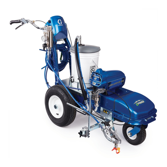
ES 1000 Airless Line Striper
1 Battery
2 Batteries
Included
Included
120V
120V
230V
230V
3A4603C
EN
ti30320a
Advertisement
Table of Contents

Related Manuals for Graco LineLazer ES 1000


Summary of Contents for Graco LineLazer ES 1000
- Page 1 1 Battery 2 Batteries Included Included Included 25M225 120V 25M226 120V 25M315 120V 25M227 230V 25M228 230V 25M316 230V ti30320a Use only genuine Graco replacement parts. The use of non-Graco replacement parts may void warranty.
-
Page 2: Table Of Contents
Electrical Specifications ....59 Graco Standard Warranty ....60... - Page 3 Warnings Warnings The following warnings are for the setup, use, grounding, maintenance, and repair of this equipment. The exclamation point symbol alerts you to a general warning and the hazard symbols refer to procedure-specific risks. When these sym- bols appear in the body of this manual or on warning labels, refer back to these Warnings. Product-specific hazard sym- bols and warnings not covered in this section may appear throughout the body of this manual where applicable.
- Page 4 • Check hoses and parts for signs of damage. Replace any damaged hoses or parts. • This system is capable of producing 3300 psi. Use Graco replacement parts or accessories that are rated a minimum of 3300 psi. • Always engage the trigger lock when not spraying. Verify the trigger lock is functioning properly.
- Page 5 Warnings EQUIPMENT MISUSE HAZARD Misuse can cause death or serious injury. • Do not operate the unit when fatigued or under the influence of drugs or alcohol. • Do not exceed the maximum working pressure or temperature rating of the lowest rated system compo- nent.
- Page 6 Warnings PERSONAL PROTECTIVE EQUIPMENT Wear appropriate protective equipment when in the work area to help prevent serious injury, including eye injury, hearing loss, inhalation of toxic fumes, and burns. This protective equipment includes but is not limited • Protective eyewear, and hearing protection. •...
-
Page 7: Tip Selection
Tip Selection Tip Selection (cm) (cm) (cm) (cm) LL5213* 2 (5) LL5215* 2 (5) LL5217 4 (10) LL5219 4 (10) LL5315 4 (10) LL5317 4 (10) LL5319 4 (10) LL5321 4 (10) LL5323 ... -
Page 8: Component Identification (Es 1000)
Component Identification (ES 1000) Component Identification (ES 1000) PRIME SPRAY ti30321a 10 Inverter circuit breakers ON/OFF switch 11 Pump Pressure control 12 Trigger safety Spray gun trigger 13 Fuse Turn control 14 Charging port Filter 15 Voltage meter Gauge 16 LED status center Prime/Pressure valves 17 Serial ID Drain and siphon hoses... -
Page 9: Battery And Charger
3 months depending on storage temperatures. The hotter the storage temperature, • The LineLazer ES 1000 is designed to work with the faster the self-discharge occurs. To prevent one or two 12V 100 Ahr DEEP CYCLE Absorbent damage to the battery, it is important to keep the Glass Mat (AGM) batteries. -
Page 10: Charging The Battery
Battery and Charger Charging the Battery 3. Plug charging cord into charging port on the unit. Connect an extension cord, minimum 12AWG (2.5mm ), to the charging cord and plug it into wall power. Replace and charge battery only in well-ventilated area and away from flammable or combustible mate- rials, including paints and solvents. -
Page 11: Grounding Procedure
Grounding Procedure (AC Wall Power) Grounding Procedure Do not place pail on a non-conductive surface such as paper or cardboard which interrupts grounding (AC Wall Power) continuity. This equipment must be grounded to reduce the risk of static sparking and electric shock. An electric shock or static spark can cause fumes to ignite or explode. -
Page 12: Grounding Procedure
Grounding Procedure (Battery Power) Grounding Procedure Do not place pail on a non-conductive surface such as paper or cardboard which interrupts grounding (Battery Power) continuity. This equipment must be grounded to reduce the risk of static sparking. Static sparking can cause fumes to ignite or explode. -
Page 13: Pressure Relief Procedure
Pressure Relief Procedure Pressure Relief Procedure 3. Turn pressure control to lowest setting. Trigger all guns to relieve pressure. This equipment stays pressurized until pressure is manually relieved. To help prevent serious injury from ti30323a pressurized fluid, such as skin injection, splashing 4. -
Page 14: Setup/Startup
Setup/Startup Setup/Startup 5. Turn On/OFF Switch to OFF. 1. Perform Pressure Relief Procedure, page 13. 2. Charge Battery, page 10. 3. Perform Grounding Procedure (AC Wall Power), ti30322a page 11, or Grounding Procedure (Battery Power), page 12, if using flammable materials. 6. -
Page 15: Switchtip And Guard Assembly
Setup/Startup 9. Turn ON/OFF Switch to ON: 13. Inspect fittings for leaks. If leaks occur, turn sprayer OFF immediately. Perform Pressure Relief Proce- dure, page 13. Tighten leaky fittings. Repeat Setup/Startup, steps 1 - 17. If no leaks, continue to trigger gun until system is thoroughly flushed. -
Page 16: Gun Placement
Gun Placement Gun Placement Another option can be to swing the gun out at an angle and rotate the tip guard. This results in better visibility for the user. Install Gun 1. Insert guns into gun holder. Tighten clamps. ti27777a Position Gun ti28130a 2. -
Page 17: Gun Positions Chart
Gun Placement Gun Positions Chart ti27786a One line One line up to 24 in. (61cm) wide Two lines One line or two lines to spray around obstacles One gun curb Two gun curb Two lines or one line up to 24 in. (61 cm) wide 3A4603C Operation, Repair, Parts... -
Page 18: Gun Arm Mounts
Gun Placement Gun Arm Mounts 3. Slide gun arm assembly into desired gun arm mounting slot. This unit is equipped with front and rear gun arm mounts. ti27797a 4. Tighten gun arm knob into gun arm mounting slot. ti27798a NOTICE Make sure all hoses, cables, and wires are properly ti30326a routed through brackets and do NOT rub on tire. -
Page 19: Installation
Gun Placement Installation Gun Cable Adjustment Adjusting the gun cable will increase or decrease the 1. Install vertical gun mount onto gun bar. gap between the trigger plate and the gun trigger. To adjust trigger gap, perform the steps below. 1. -
Page 20: Straight Line Adjustment
Gun Placement 4. Roll the striper. Repeat steps 2 and 3 until striper Straight Line Adjustment rolls straight. Tighten bolt on wheel alignment plate to lock the new wheel setting. The front wheel is set to center the unit and allow the operator to form straight lines. -
Page 21: Paint Stripe Width
Paint Stripe Width Paint Stripe Width 1. Adjust gun up or down to change paint stripe width. 2. Trigger gun and spray test pattern. Slowly adjust pressure to eliminate heavy edges. Use smaller tip size if pressure adjustment can not eliminate heavy edges. -
Page 22: Cleanup
Cleanup Cleanup Fast Flush Drain Tube 6. Remove fluid intake and drain tube from paint, wipe excess paint off outside. 1. Perform Pressure Relief Procedure, page 13. 2. Remove guard and SwitchTip from all guns. ti24709a TI3371A 7. Place siphon tube set in grounded metal pail partially filled with flushing fluid. -
Page 23: Fast Flush Hose And Gun
Cleanup Fast Flush Hose and Gun 12. Stop triggering gun. 13. Fill pump with Pump Armor and reassemble filter, 10. To flush airless hose and spray gun, turn prime guard and SwitchTip. valve horizontal. 14. Each time you spray and store, fill throat packing 11. -
Page 24: Maintenance
Maintenance Maintenance Routine maintenance is important to ensure proper operation of your sprayer. Maintenance includes performing routine actions which keep your sprayer in operation and prevents trouble in the future. Activity Interval Inspect/clean sprayer filter, fluid inlet strainer, and gun filter. Daily or each time you spray Inspect motor shield vents for blockage. -
Page 25: Troubleshooting
Troubleshooting Troubleshooting Mechanical/Fluid Flow , page 13, before Follow Pressure Relief Procedure checking or repairing. 2. Check all possible problems and causes before dis- assembling the unit. What to Do What to Check When check is not OK, refer to this Problem If check is OK, go to next check column... - Page 26 Troubleshooting What to Do What to Check When check is not OK, refer to this Problem If check is OK, go to next check column Motor runs but pump does not stroke Connecting rod assembly damaged. Replace connecting rod assembly. See pump manual.
-
Page 27: Electrical
2. Turn pressure control knob clockwise 1/2 turn. equals CODE 02). Error Code Messages CODE MESSAGE ACTION HIGH PRESSURE DETECTED - Check for clogs. Use only Graco spray hoses, use a RELIEVE PRESSURE minimum of 50ft/15m. PRESSURE TRANSDUCER NOT Check transducer connection. DETECTED MOTOR NOT SPINNING Check for mechanical failure and check motor connections. - Page 28 Troubleshooting Problem What to Check How to check Sprayer does not run at all Check transducer or transducer Make sure there is no pressure in the system (see Pressure Relief Procedure, page 13). Check fluid path connections for clogs, such as clogged filter. Control board status light blinks 2 Use airless paint spray hose with no metal braid.
- Page 29 Troubleshooting Problem What to Check How to check Sprayer does not run at all Control is commanding motor to Remove pump and try to run sprayer. If motor runs, run but motor shaft does not check for locked or frozen pump or drive train. rotate.
- Page 30 Troubleshooting Problem What to Check How to check Perform Field Short Test: Test at large 4-pin motor field connector. There should not be continuity from pin 4, the ground wire, and any of the remaining 3 pins. If motor field connector tests fail, replace motor.
- Page 31 Troubleshooting Problem What to Check How to check Output circuit breaker tripped Check circuit breaker and reset if necessary, page 35. No AC output voltage and indicator lights ON. Low battery Check the condition of the batteries and recharge if AC output voltage is low and the inverter turns loads OFF in a short possible.
-
Page 32: Sprayer Will Not Run
Troubleshooting Sprayer Will Not Run (See following page for steps) Remove Control box cover. Turn sprayer ON. Observe control board status light on See Step 1. Do you control board (see page 27). have over 100 VAC (220 VAC for 230v units)? No Light Once Normal Operation... - Page 33 Troubleshooting Step 1: Step 2: Step 3: Plug Power cord in and turn Check motor thermal switch. Disconnect potentiometer. switch ON. Connect probes Unplug yellow wires. Meter Plug power cord in and to ontrol board. Turn meter to should read 100 ohms. turn switch ON.
-
Page 34: Sprayer Will Not Shut Off
Troubleshooting Sprayer Will Not Shut Off 1. Perform Pressure Relief Procedure, page 13. 2. Remove control box cover so the control board Leave prime valve open (down) and turn ON/OFF status light can be viewed if available. switch OFF. Troubleshooting Procedure Plumb pressure gauge into paint hose, Mechanical problem: plug sprayer in, and turn power switch ON. -
Page 35: Inverter
Troubleshooting Inverter The inverter has 2 circuit breakers, and an LED Status Center that communicates inverter operation status. See chart below for different functions, alarms, and fault modes. Status Center BATTERY POWER OVER OVER UNIT FLOAT FAST INVERTER LINE TYPE SAVER LOAD TEMP... -
Page 36: Sprayer Does Not Have 100 Vac (220 Vac For 230V Units)
Troubleshooting Sprayer does not have 100 VAC (220 VAC for 230V units) Troubleshooting Procedure: Sprayer doesn t have 100VAC See Step 4 on page 33. Remove front shroud on unit to Do you have Is Fuse access DC power connections 10.0 volts or higher? blown? on inverter. -
Page 37: Battery Will Not Charge
Troubleshooting Battery Will Not Charge Troubleshooting Procedure: Remove front shroud on unit to See Step 4 on page 33. Is Fuse Do you have access DC power connections blown? 10.0 volts or higher? on inverter. Remove paint bucket tray to Replace access fuse and battery. -
Page 38: Parts Drawing - Linelazer Es 1000
Parts Drawing - LineLazer ES 1000 Parts Drawing - LineLazer ES 1000 Torque to 17-23 ft-lbs (23.0-31.1 N·m) Torque to 190-210 in-lbs (21.4-23.7 N·m) Torque to 18-22 in-lbs (2.0-2.4 N·m) Torque to 23-27 ft-lbs (31.1-36.6 N·m) Torque to 45-55 ft-lbs (61.0-74.5 N·m) -
Page 39: Parts List
Parts List Parts List Ref. Part Description Ref. Part Description 129601 SCREW, cap, btn hd, 3/8 x 1.25 17N763 FRAME, linestriper 17N451 CONTROL, assembly, LL ES 108851 WASHER, plain 867517 SCREW, hex head, 3/8-16 x 3.5” 101566 NUT, lock 17J135 COVER, control 193405 AXLE 278723 GASKET, pail 198891 BRACKET... -
Page 40: Parts Drawing - Linelazer Es 1000
Parts Drawing - LineLazer ES 1000 Parts Drawing - LineLazer ES 1000 Torque to 140-160 in-lbs (15.8-18.1 N·m) Torque to 30-35 in-lbs (3.4-4.0 N·m) Hammer tight Torque to 9-11 in-lbs (1.0-1.2 N·m) Torque to 20-25 in-lbs (2.3-2.8 N·m) 125 127... -
Page 41: Parts List
Parts List Parts List Ref. Part Description Ref. Part Description 278723 GASKET, pail 17P496 COVER, inverter 115099 WASHER, garden 125205 NUT, lock, nylon, 3/8-16 117559 O-RING 24S022 MOTOR, electric 17N217 HOSE, coupled 129604 GROMMET, rubber 187651 STRAINER, 3/4-16 unf 17N444 GROMMET 107254 SCREW, thd forming 278204 CLIP, drain line 17N730 LABEL, front, bottom... -
Page 42: Parts Drawing - Linelazer Es 1000
Parts Drawing - LineLazer ES 1000 Parts Drawing - LineLazer ES 1000 Torque to 8-10 ft-lbs (10.8-13.6 N·m) see pg. 50 ti30463a 3A4603C Operation, Repair, Parts... -
Page 43: Parts List
Parts List Parts List Ref. Part Description Ref. Part Description 17M321 CABLE, red, dia .625 x 3 ft 17N508 INVERTER, power supply, 120V (includes 615) 17N509 INVERTER, power supply, 230V 17M323 CABLE, black, dia .625 x 3.5 ft 17N448 BATTERY 113796 SCREW, flanged, hex hd w/ cover (includes 614) 16A390 NUT, hex, flanged... -
Page 44: Parts Drawing - Linelazer Es 1000
Parts Drawing - LineLazer ES 1000 Parts Drawing - LineLazer ES 1000 Torque to 17-23 ft-lbs (23.0-31.1N·m) Torque to 190-210 in-lbs (21.4-23.7 N·m) Torque to 23-27 ft-lbs (31.1-36.6 N·m) Torque to 60-80 in-lbs (6.7-9.0 N·m) Torque to 17-23 ft-lbs (23.0-31.1 N·m) Torque to 35-45 ft-lbs (47.4-61.0 N·m) -
Page 45: Parts List
Parts List Parts List Swivel Wheel Assembly Filter Ref. Part Description Ref. Part Description 101566 NUT, lock 17K166 MANIFOLD, filter 196179 FITTING, elbow, street 15C765 CAP, filter 112960 SCREW, cap, flng hd 15C766 TUBE, diffusion 111040 NUT, lock, insert, nylock, 5/16 243984 FILTER, fluid 18*‡... -
Page 46: Parts Drawing - Linelazer Es 1000
Parts Drawing - LineLazer ES 1000 Parts Drawing - LineLazer ES 1000 ti30465a Torque to 17-23 ft-lbs (23.0-31.1 N·m) Torque to 145-155 in-lbs (16.3-17.5 N·m) ti30466a 3A4603C Operation, Repair, Parts... -
Page 47: Parts List
Parts List Parts List Gun Holder and Arm Gun Trigger Ref. Part Description Ref. Part Description 101566 NUT, lock 114659 GRIP, handle 114982 SCREW, cap, flng hd 15F624 NUT, cable, gun 17N447 BRACKET, gun arm 198896 BLOCK, mounting 102040 NUT, lock, hex 245676 HANDLE 17J407 ARM, extension, bar, weldment 198895 PLATE, lever, pivot... -
Page 48: Parts Drawing - Linelazer Es 1000
Parts Drawing - LineLazer ES 1000 Parts Drawing - LineLazer ES 1000 Torque to 18-22 in-lbs (2.0-2.4 N·m) Torque to 28-32 in-lbs (3.1-3.6 N·m) Torque to 45-55 ft-lbs (61.0-74.5 N·m) ti30487a 3A4603C Operation, Repair, Parts... -
Page 49: Parts List
Parts List Parts List Ref. Part Description Ref. Part Description 17N443 POTENTIOMETER 241105 CABLE 198650 SPACER, shaft 17J136 SCREW, hex, flange hd 17J126 BRACKET, shroud 113491 CLAMP, wire 17N419 BRACKET, switch 114659 GRIP, handle 102040 NUT, lock, hex 237686 GROUNDING, clip 15C973 GASKET 194310 LEVEL, actuator 17N416 LABEL, control... -
Page 50: Voltage Meter Box, 120V
Voltage Meter Box, 120V Voltage Meter Box, 120V Torque to 8-11 in-lbs (0.9-1.2 N·m) Torque to 10-15 in-lbs (1.1-1.7 N·m) Torque to 2-4 in-lbs (0.2-0.4 N·m) 620a 624a 622a 626a 625a Voltage Meter Box, 230V Torque to 8-11 in-lbs (0.9-1.2 N·m) Torque to 10-15 in-lbs 624b (1.1-1.7 N·m) -
Page 51: Parts List
Parts List Parts List Voltage Meter Box, 120V Voltage Meter Box, 230V Ref. Part Description Ref. Part Description 620a 17R015 PANEL, box, meter, voltage, 120V 620b 17N929 PANEL, box, meter, voltage, 230V 17N638 METER, volt, digital 17N638 METER, volt, digital 622a 25M487 KIT, repair, bear, relay, 120V 622b 25M489 KIT, repair, bear, relay, 230V 104714 SCREW, mach, pnh... -
Page 52: Control Box, 120V
Control Box, 120V Control Box, 120V Torque to 20-25 in-lbs (2.3-2.8 N·m) 650a Torque to 12±2 in-lbs (1.4 ± 2 N·m) Torque to 30-35 in-lbs (3.4-3.9 N·m) ti30522a Control Box, 230V Torque to 20-25 in-lbs (2.3-2.8 N·m) Torque to 12±2 in-lbs 650b (1.4 ±... -
Page 53: Parts List
Parts List Parts List Control Box, 120V Control Box, 230V Ref. Part Description Ref. Part Description 117501 SCREW, mach, slot hex wash hd 117501 SCREW, mach, slot hex wash hd 277229 COVER, control 277229 COVER, control 650a 25M490 BOX, control board, 120V, includes 650b 25M491 BOX, control board, 230V, includes 651, 652, 653, 654, 655, 657, 658 651, 652, 653, 654, 655, 656, 657,... -
Page 54: Wiring Diagram
Wiring Diagram ti30550a 3A4603C Operation, Repair, Parts... - Page 55 Wiring Diagram ti30551a 3A4603C Operation, Repair, Parts...
-
Page 56: Control Board Wiring Diagram
Control Board Wiring Diagram Control Board Wiring Diagram 110/120V MOTOR Potentiometer Pressure Transducer Black To Power Plug Green ti30332a 3A4603C Operation, Repair, Parts... - Page 57 Control Board Wiring Diagram 230V NOTICE Heat from inductor coil of filter board may destroy wire insulation that comes in contact with it. Exposed wires could cause shorts and component damage. Bundle and tie loose wires so none lay in contact with inductor coil on the filter board.
-
Page 58: Technical Specifications
Technical Specifications Technical Specifications LineLazer ES 1000 with 1 battery U.S. Metric Dimensions Height (with handle bar down) Unpackaged - 44.5 in. Unpackaged - 113.03 cm Packaged - 53.0 in. Packaged - 134.62 cm Width Unpackaged - 34.25 in. Unpackaged - 86.99 cm Packaged - 39.0 in. -
Page 59: Electrical Specifications
Electrical Specifications Electrical Specifications LineLazer ES 1000 DC Input Nominal Input Voltage 12.0Vdc Minimum Start Voltage 10.0Vdc Low Battery Alarm 11.0Vdc Low Battery Trip 10.5Vdc High Voltage Alarm & Fault 16.0Vdc High DC Input Recovery 15.5Vdc Low Battery Voltage Recovery 13.0Vdc... -
Page 60: Graco Standard Warranty
With the exception of any special, extended, or limited warranty published by Graco, Graco will, for a period of twelve months from the date of sale, repair or replace any part of the equipment determined by Graco to be defective.