
Related Manuals for Trane SmartGen HSC940


Summary of Contents for Trane SmartGen HSC940
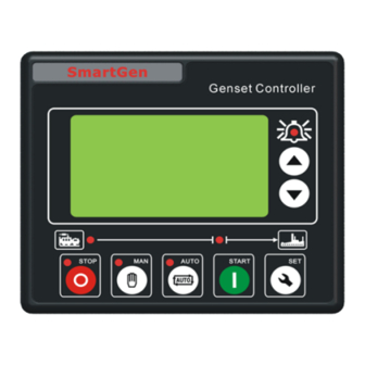
- Page 1 Owner’s Manual SmartGen® HSC940 Controller Note: “Graphics in this document are for representation only. Actual model may differ in appearance.” March 2017 032-5094-1A-EN...
-
Page 2: Table Of Contents
Table Of Contents Overview ......3 Performance & Characteristics ....4 Specifications . -
Page 3: Overview
Overview HSC940 genset controllers integrate digitization, intellectualization and network technology which are used for gas genset automation and monitor control system of single unit to achieve automatic start/stop, data measure, alarm protection, three remote: remote control, remote measuring and remote communication (SG485 module must be fitted) and speed regulation. -
Page 4: Performance & Characteristics
Performance & Characteristics HSC940, used for single automation systems; it regulates the speed simply by adjust the throttle opening via the driving stepper motor; auto start/stop of the unit are performed with the help of remote signal. Key characteristics • 132×64 LCD with backlight, multilingual interface (including Chinese, English, Spanish and Russian), pushbutton operation;... -
Page 5: Specifications
Specifications Items Contents Operating Voltage DC8.0V to DC35.0V, Continuous Power Supply. Power Consumption Standby: ≤2W Working: <8W (When driving stepper motor is regulating) Alternator Input Range 3-Phase 4-Wire AC15V - AC360V (ph-N) 2-Phase 3-Wire AC15V - AC360V (ph-N) Single-Phase 2-Wire AC15V - AC360V (ph-N) 3-Phase 3-Wire AC30V - AC620V (ph-ph) -
Page 6: Operations
Operation 4.1 KEY OPERATIONS Stop running generator in Auto/Manual mode; Lamp test (press Stop/ Reset at least 3 seconds); Reset alarm if alarm occurs; During stopping process, press this button again to stop generator immediately. Start Start genset in Manual/Test mode. Pressing this key will set the module into Manual mode. -
Page 7: Auto Start/Stop Operation
Operation 4.3 AUTO START/STOP OPERATION Auto mode is selected by pressing the button; a LED besides the button will illuminate to confirm the operation. Automatic Start Sequence: 1. When “Remote Start” is active, “Start Delay” timer is initiated; 2. “Start Delay” countdown will be displayed on LCD; 3. -
Page 8: Manual Start/Stop Operation
Operation 4.4 MANUAL START/STOP OPERATION 1. MANUAL START: Manual mode is selected by pressing the button; a LED besides the button will illuminate to confirm the operation. Then press button to start the genset; can detect crank disconnect condition and generator accelerates to high-speed running automatically. -
Page 9: Protection
Protection 5.1 WARNINGS Warnings are not shutdown alarms and do not affect the operation of the genset. Warning alarms does not lead to shutdown and the alarm information will be displayed on the LCD. Warning alarms types are as follows: Type Description When the controller detects that there is High Temperature input and... -
Page 10: Shutdown Alarms
Protection 5.2 SHUTDOWN ALARM When controller detects shutdown alarm, it will send signal to open breaker and shuts down generator. Besides, the alarm information will be displayed on the LCD. Shutdown alarms as following: Type Description When the controller detects that there is Emergency Stop input, it will ini- Emergency Stop tiate a shutdown alarm and the alarm information will be displayed on the LCD. - Page 11 Protection 5.2 SHUTDOWN ALARM continued When controller detects shutdown alarm, it will send signal to open breaker and shuts down generator. Besides, the alarm information will be displayed on the LCD. Shutdown alarms as following: Type Description No gens freq When the controller detects the generator frequency is 0, it will initiate a shutdown alarm and the alarm information will be displayed on the LCD.
-
Page 12: Wiring Connections
Wiring Connections HSC940 controller’s rear as following: Description of terminal connection: Function Cable Size Remarks 2.5mm Connected with negative of starter battery Connected with positive of starter battery. Max. 20A fuse is 2.5mm recommended. EM. Stop 1.5mm Connected with B+ via emergency stop button Fuel 1.0mm Fuel relay output;... - Page 13 Wiring Connections Continued: Function Cable Size Remarks Aux. Input 1 1.0mm Ground connected is active (B-) Aux. Input 2 1.0mm Ground connected is active (B-) Details see Aux. Input 3 1.0mm Ground connected is active (B-) form 3 Aux. Input 4 1.0mm Ground connected is active (B-) Aux.
-
Page 14: Scope & Definition Of Configurable Parameters
Scope & Definitions of Configurable Parameters 7.1 CONTENTS AND SCOPES OF PARAMETERS Form 1 Items Range Default Description Time from remote start signal is active to start gen- Start Delay (0-3600)s set. Time from remote start signal is deactivated to gen- Stop Delay (0-3600)s set stop. - Page 15 Scope & Definitions of Configurable Parameters 7.1 CONTENTS AND SCOPES OF PARAMETERS continued Form 1 continued Items Range Default Description Tooth number of the engine, for judging of starter Flywheel Teeth (1-300) crank disconnect conditions and inspecting of engine speed. See the installation instructions. The alarm delay of generator over voltage and under Gen Abnormal Delay (0-20.0)s...
- Page 16 Scope & Definitions of Configurable Parameters 7.1 CONTENTS AND SCOPES OF PARAMETERS continued Form 1 continued Items Range Default Description During generator is normal running, when alternator Charge Alt Failure (0-30)V D+(WL) voltage has fallen below the set value and (Warning) remains for 5s, It will initiate a shutdown alarm signal.
- Page 17 Scope & Definitions of Configurable Parameters 7.1 CONTENTS AND SCOPES OF PARAMETERS continued Form 1 continued Items Range Default Description Auxiliary Input 4 (0-1) Factory default: Close to active Active Auxiliary Input 4 (0-20.0)s Delay Auxiliary Input 5 (0-15) Factory default: Warn Input Auxiliary Input 5 (0-1) Factory default: Close to active...
- Page 18 Scope & Definitions of Configurable Parameters 7.1 CONTENTS AND SCOPES OF PARAMETERS continued Form 1 continued Items Range Default Description (0-6000) r/ Idle Speed Offer standard to adjust idle speed. The rising speed rate during the process of genset Idle Slope 0-6000 change idle running status into rated speed running status.
-
Page 19: Enable Definitions Of Programmable Output Ports
Scope & Definitions of Configurable Parameters 7.1 CONTENTS AND SCOPES OF PARAMETERS continued Note 1. If “high temperature inhibit” is configured, or set auxiliary input as “inhibit high temperature stop” and this input is active, when temperature is higher than the preset value, or high temperature alarm input is active, controller will send warning signal only and not stop the unit. - Page 20 Scope & Definitions of Configurable Parameters 7.2 ENABLE DEFINITION OF PROGRAMMABLE OUTPUT PORTS continued Form 2 continued Items Description Close when the generator enters into Stop Idle delay/ Energized to Stop Drop Speed delay (close time: Stop Idle delay) while open when Aux. Drop Speed input is active.
-
Page 21: Defined Contents Of Configurable Input Ports
Scope & Definitions of Configurable Parameters 7.2 DEFINED CONTENTS OF CONFIGURABLE INPUT PORTS (ALL ACTIVE WHEN CONNECT TO GRAND (B-)) Form 3 Items Description Not Used High Temperature Input If these signals are active after safety on delay, shutdown alarm will be im- mediately initiated. -
Page 22: Conditions Of Crank Disconnect Selection
Protection 7.4 CONDITIONS OF CRANK DISCONNECT SELECTION Form 4 Setting Description Gen frequency Speed sensor Speed sensor + Gen frequency NOTES: 1. There are 2 conditions to make starter disconnected with engine, that is, speed sensor and generator frequency. They all can be used separately. We recommend that speed sensor should be using with generator frequency together, in order to make the starter motor is separated with engine immediately and can check crank disconnect exactly. -
Page 23: Parameter Settings
Parameter Settings Start the controller, then press to enter into the parameters setting menu, see fig 1 below: 1. Set Parameters 2. Information 3. Language Fig. 1 4. Time and Date Parameters Setting When entering password interface, input correct password (default: 1234) can set all of the parameter items in Form 1. -
Page 24: Commissioning
Commissioning Please make the under procedures checking before commissioning, 1. Ensure all the connections are correct and wires diameter is suitable. 2. Ensure that the controller DC power has fuse, controller‘s positive and negative connected to start battery are correct. 3. -
Page 25: Typical Application
Typical Application Typical Application Diagram CAUTION! Expand relay with high capacity in start and fuel output is recommend. CAUTION! Expand relay must be used in generator closed outputs. Connection Between Controller and Genset 032-5094-1A-EN... -
Page 26: Installation
Installation 12.1 FIXING CLIPS Controller is panel built-in design; it is fixed by clips when installed. 1. Withdraw the fixing clip screw (turn anticlockwise) until it reaches proper position. 2. Pull the fixing clip backwards (towards the back of the module) ensuring two clips are inside their allotted slots. -
Page 27: Overall Dimension And Panel Cutout
Installation 12.2 OVERALL DIMENSION AND PANEL CUTOUT 1. Battery Voltage Input HSC940 controller can suit for widely range of battery voltage DC(8~35)V. Negative of battery must be connected with the engine shell. The diameter of wire which from power supply to battery must be over 2.5mm2. -
Page 28: Gsm Short Message Alarm And Remote Control
GSM Short Message Alarm & Remote Control 13.1 GSM SHORT MESSAGE ALARM When controller detects alarm, it will send short message to phone automatically. 13.2 GSM SHORT MESSAGE REMOTE CONTROL Users send order message to GSM module, then controller will make actions according to this SMS order and pass back corresponding operations information. -
Page 29: Gsm Short Message Alarm
GSM Short Message Alarm & Remote Control 13.2 GSM SHORT MESSAGE REMOTE CONTROL continued Users send order message to GSM module, then controller will make actions according to this SMS order and pass back corresponding operations information. Controllers only execute the orders by pre-set. Detail orders as following: SMS Orders Pass Back Information... -
Page 30: Fault Finding
Fault Finding Symptoms Possible Solutions Check starting batteries; Controller no response with Check controller connection wirings; power. Check DC fuse. Check the water/cylinder temperature is too high or not; Genset shutdown Check the genset AC voltage; Check DC fuse. Low oil pressure alarm after crank Check the oil pressure sensor and its connections. - Page 31 Smartgen — make your generator smart Smartgen Technology Co., Ltd. No.28 Jinsuo Road Zhengzhou Henan Province P. R. China Tel: 0086-371-67988888/67981888 0086-371-67991553/67992951 0086-371-67981000(overseas) Fax: 0086-371-67992952 Web: http://www.smartgen.com.cn http://www.smartgen.cn Email: sales@smartgen.cn All rights reserved. No part of this publication may be reproduced in any material form (including photocopying or storing in any medium by electronic means or other) without the written permission of the copyright holder.
- Page 32 032-5094-1A-EN (9 Mar 2017) We are committed to using environmentally conscious print practices. © 2017 Ingersoll Rand IR000000...