Table of Contents
Advertisement
Quick Links
Owner's Manual and Installation Instructions
IC-600PL 6-station Controller expandable to 30 stations, Plastic Cabinet
IC-600M 6-station Controller expandable to 42 stations, Metal Cabinet
IC-600PP 6-station Controller expandable to 42 stations, Plastic Pedestal
IC-600SS 6-station Controller expandable to 42 stations, Stainless Steel
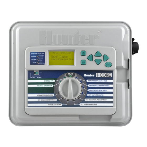
Commercial Irrigation Controller
RAIN SENSOR
ACTIVE
BYPASS
SYSTEM OFF
MANUAL OPERATION
SETTINGS
ADVANCED FEATURES
SET SENSOR OPERATION
CYCLE AND SOAK
SET CURRENT DATE / TIME
SET PROGRAM START TIMES
SET STATION RUN TIMES
SET DAYS TO WATER
SET SEASONAL ADJUSTMENT
SET PUMP OPERATION
Advertisement
Table of Contents
Troubleshooting

Related Manuals for Hunter IC-600SS


Summary of Contents for Hunter IC-600SS
- Page 1 Owner’s Manual and Installation Instructions IC-600PL 6-station Controller expandable to 30 stations, Plastic Cabinet IC-600M 6-station Controller expandable to 42 stations, Metal Cabinet IC-600PP 6-station Controller expandable to 42 stations, Plastic Pedestal IC-600SS 6-station Controller expandable to 42 stations, Stainless Steel...
-
Page 3: Table Of Contents
Bypassing the Sensor(s) ....................39 Dimensions ................10 Sensor Bypass Switch ..................39 Default Settings ConneCtIng a hunter SoLar SynC ............ 11 fCC notICe ....................39 ........... 12 ConneCtIng a fLoW SenSor (oPtIonaL) ........13 ConneCtIng a reMote ControL (oPtIonaL) PoWer faILureS .................. -
Page 4: Introduction
InTrOduCTIOn The Hunter I-Core controller is a full-featured controller for demanding commercial and high-end residential applications. Versatility is what makes the I-Core one of Hunter’s highest performing irrigation controllers. I-Core features include: note: • Modular design expandable from 6 to 30 stations... -
Page 5: I-Core Wiring Compartment And Interior
I-COre WIrIng COMparTMenT and InTerIOr battery Compartment (9-volt alkaline battery) – The alkaline battery (not included) keeps time during power outages. The user may also program the controller without AC power. battery Compartment (CR2032 3-volt lithium) – The lithium battery provides backup timekeeping during power outages and when the 9-volt is not installed (location is on the back of the facepack). -
Page 6: Mounting The Controller To Wall
MOunTIng The COnTrOller TO Wall Wall Mount for plastic and Metal Cabinet All necessary mounting hardware is included with your controller and should be suitable for most installations. Tools required: • Long drill bit and extension Philips screwdriver or bit (for use with long extension) –... -
Page 7: Mounting The Controller (Metal Pedestal)
MOunTIng The COnTrOller (MeTal pedesTal) pedestal Mount for Metal/stainless Cabinet ½" (13 mm)Conduit Nut 2" (50 mm)Conduit Nut Location requirement: A) A switch or circuit-breaker shall be included in building installations; B) the switch or breaker shall be in close proximity ½"... -
Page 8: Connecting Ac Power
COnneCTIng aC pOWer nOTe: It is recommended that a licensed electrician perform the following power installation. The I-Core can operate with either 120VAC or 230VAC power. Supply wires must be 14AWG or larger. Turn AC power off at the source, and verify that it is off. Remove the cover from the junction box. -
Page 9: Connecting Earth Ground
COnneCTIng earTh grOund The I-Core features a ground lug, which is isolated from the primary AC power, and is used to ground incoming surges from the communications and output valve wires. Do NOT connect the primary AC 120/230V electrical ground wire to the earth ground lug. -
Page 10: Connecting The Power And Station Modules
COnneCTIng The pOWer and sTaTIOn MOdules station Module Installation The I-Core controller is supplied with one factory installed power module and one station module for six stations. Additional station modules may be Open the inner facepack door and locate the Slide Lock. Move the added in six station increments to expand the controller’s station capability. -
Page 11: Connecting Valve Wires
Each station output is rated for 0.56A max, or enough to operate two controller directly to the pump — damage to controller will result. Hunter AC solenoids simultaneously. Route valve wires between Master Valve or Pump Start Relay location Route valve wires between control valve location and the controller. -
Page 12: Connecting A Weather Sensor (Optional And Not Included)
COnneCTIng a WeaTher sensOr (OpTIOnal and nOT InCluded) The I-Core controller has the ability of connecting two Hunter Sensors If the rain sensor switch is left in the ACTIVE position but no sensor is (three with I-Core Metal) including: connected and the jumper wire has been removed, the display on the I-Core will indicate that the sensor is ACTIVE. -
Page 13: Connecting A Hunter Solar Sync
COnneCTIng a hunTer sOlar synC The Solar Sync is a “smart“ control system that, when connected to the I-Core, will automatically adjust your controller’s station run times based upon changes in local climate conditions. The Solar Sync incorporates a solar and temperature sensor to determine evapotranspiration, also known as ET. -
Page 14: Connecting A Flow Sensor (Optional)
The I-Core is designed to operate primarily with the Hunter HFS Flow Sensors. However, some non-Hunter flow sensors can be used. To connect a Hunter HFS Flow Sensor, route the pair of 18 AWG (1 mm) wires from the sensor into the cabinet (max distance of 1,000 ft.). -
Page 15: Connecting A Remote Control (Optional)
Refer to the remote control owner's If there are stations within the program that follow this station numerically manual for further information on how to operate your Hunter remote. and are NOT programmed to the sensor, these stations will run and the... -
Page 16: Power Failures
pOWer faIlures Due to the possibility of power failures, the I-Core has nonvolatile memory to preserve programming data indefinitely. The 9-volt battery is required for programming of the controller in the absense of AC power. Both the 9-volt battery and lithium battery (if a 9-volt battery is not installed), will maintain the current time and day during power outages. -
Page 17: Controller Programming
1. the rest of the start times 2 through 8 would be left blank --:--. The I-Core controller has the ability to operate five Hunter valves at one time, and, therefore, allows for more than one program to run at the same time. -
Page 18: Selecting Specific Days Of The Week To Water
COnTrOller prOgraMMIng (COnTInued) selecting Odd or even days to Water This feature uses numbered days of the month for watering instead of nOTe: When entering run times the Seasonal adjusted specific days of the week. (For example, Odd Days 1st, 3rd, 5th, etc. and run time will be displayed in the lower right corner of Even Days 2nd, 4th, 6th, etc.) the display. -
Page 19: Set Seasonal Adjustment
Global Seasonal Adjust value. Solar Sync adjust (by Solar Sync) – This mode allows seasonal adjustment to occur on a daily basis when a Hunter Solar Sync is connected to the controller. This provides for the maximum amount of water saving while promoting healthy plant material. -
Page 20: Set Pump Operation
COnTrOller prOgraMMIng (COnTInued) Cycle will flash OFF. Use the + / – button to set the Cycle time. You The Solar Sync will take over and the percentage will change according to the findings of the Solar Sync sensor. If you set seasonal adjust mode to may select a maximum Cycle time of up to 60 minutes. - Page 21 COnTrOller prOgraMMIng (COnTInued) Rotate the dial to the seT sensOr OperaTIOn position. Use the ◄ and ► buttons to select the station that you would like to program a sensor response. The default is to have the sensor input active for each station, therefore indicating a .
-
Page 22: Manual Program
Turn the dial to run, and the station will begin irrigating. program or station at the same time, because the I-Core has the ability to Up to five Hunter valves can be operated simultaneously. run up to five stations or events at once. To initiate multiple events, you... -
Page 23: System Off
COnTrOller prOgraMMIng (COnTInued) If the user has not selected a station’s flow to be monitored the controller Once the correct station number is displayed, turn the dial to Run. Again, will display no flow station, as well as no runtime even if there is a run the controller will go into its diagnostic flow testing for that particular station. -
Page 24: Advanced Features
The Sensor Configure feature allows you to program the SEN1 or SEN2 terminals to accept a Hunter Clik-type sensor, a Solar Sync sensor, an HFS flow sensor, or a non-Hunter flow sensor. It is important to program the correct flow sensor size. -
Page 25: Flow Operation
adVanCed feaTures (COnTInued) • expected flow – the amount of flow expected for that station in Gallons Per Minute (GPM )or Liters Per Minute (LPM) • overflow – Can be set from 110% to 300% of Expected Flow. During system operation, if the station flow exceeds the Overflow limit, the controller will shut the system down and begin diagnostic testing. -
Page 26: Station Delay
adVanCed feaTures (COnTInued) station delay This feature allows the user to insert a delay time between when one station turns off and the next station turns on. This is very helpful on systems with slow closing valves, or on pump systems that are operating near maximum flow or have slow well recovery. -
Page 27: To Save Your Watering Program Into Memory
adVanCed feaTures (COnTInued) To save your watering program into memory: Total Watering Time Turn the dial to the adVanCed feaTures position. Use the ▲ and The Total Watering Time feature displays the total run time of all stations ▼ to select easy retrieve Memory and use the + button to enter. in a particular Program. -
Page 28: Lcd Adjust
adVanCed feaTures (COnTInued) Use the ▼ button to select point B. The ► cursor will be displayed next to lCd adjust point B. To reset reference point B, press and hold the + button, the date The LCD Adjust feature allows you to increase or decrease the contrast of will change to the current date and the gallons will be set back to 0. -
Page 29: Programming Solar Sync Settings
prOgraMMIng sOlar synC seTTIngs The table will assist you in identifying the type of region you live in. There are four basic ET regions, each with descriptions of the region, along with typical ET and temperature characteristics. It is recommended that, if possible, the region be chosen based upon average July ET or peak summer ET (inches/mm per day). -
Page 30: Clearing Et Memory
prOgraMMIng sOlar synC seTTIngs (COnTInued) Clearing eT memory programming solar sync delay Once the Solar Sync Sensor is installed the controller will begin I-Core with built in Solar Sync has the ability to delay the automatic, daily collecting ET data. This ET data can be erased/cleared if desired. update of the seasonal adjustment value from Solar Sync for up to 99 days. -
Page 31: Hidden Features
hIdden feaTures The stations run time will be flashing. Use the ◄ or ► buttons to select the programmable rain Off station within the program you would like the manual to begin with, and The Programmable Rain Off allows the user to set period of time in which use the + / –... - Page 32 (COnTInued) The Learn Expected Flow display will also indicate if there is a problem with For non-Hunter flow sensors, Custom 1, Custom 2, or Custom 3 (Metal any programming. If station run times were not programmed in the set Version I-Core) can be selected as a flow sensor type.
-
Page 33: Controller Diagnostics And Troubleshooting
COnTrOller dIagnOsTICs and TrOubleshOOTIng system status dashboard station status The System Status Dashboard is a quick reference indicator that uses LED The Station System Status light monitors and indicates whether a station lights to provide system status information regarding sensor status, valve is operating normally or if an overcurrent condition for a particular station operation, and flow monitoring. - Page 34 COnTrOller dIagnOsTICs and TrOubleshOOTIng (COnTInued) Once a minute has passed, the controller will again activate the station (the The I-Core can activate stations simultaneously. After the Start Delay display will still indicate that it is Isolating the Flow Alarm). After the Start elapses for the flow monitored station, if the controller detects overflow, Up delay has elapsed, if the station flow resembles the learned flow, the it will initiate a diagnostic testing procedure.
-
Page 35: Hunter Quick Check
QuICK CheCK ™ The Hunter Quick Check is an efficient and effective way to diagnose problems in the field. Instead of having to physically check each field wiring circuit for potential problems, the user can run the Hunter Quick Check circuit test procedure. -
Page 36: Troubleshooting
TrOubleshOOTIng problem Causes solutions No display. Check AC power to controller. Fix power supply. 14-Pin connector is not fully connected. Connect ribbon cable on back of facepack door. Module locking bar is in the Power Off Slide the module locking bar into the Power On position. position. - Page 37 TrOubleshOOTIng problem Causes solutions Rain or other Clik sensor does not shut Incorrect sensor type or connection Use one normally-closed Clik-type sensor per sensor ports. down system. (Jumper installed). Verify that one wire from each sensor is to each SEN1 or SEN2 terminals.
-
Page 38: I-Core: Institutional/Commercial Controller (Ic-600Pl & Ic601Pl) - Plastic Cabinet
I-COre: InsTITuTIOnal/COMMerCIal COnTrOller (IC-600pl & IC601pl) – plasTIC CabIneT Item Description Catalog No. Front Panel 124705 Knob 129300 Rear Cabinet 117805 RAIN SENSOR ACTIVE BYPASS SET CURRENT DATE / TIME SYSTEM OFF Door Without Lock, Plastic I-Core 131305 MANUAL OPERATION SET PROGRAM START TIMES SETTINGS SET STATION RUN TIMES... -
Page 39: I-Core: Institutional/Commercial Controller (Ic-800M & Ic-800Ss) - Metal Cabinet
I-COre: InsTITuTIOnal/COMMerCIal COnTrOller (IC-800M & IC-800ss) – MeTal CabIneT Item Description Catalog No. Front Panel 124705 Knob 129300 RAIN SENSOR ACTIVE BYPASS SYSTEM OFF SET CURRENT DATE / TIME Door Without Lock, Metal I-Core 125500 MANUAL OPERATION SET PROGRAM START TIMES SETTINGS SET STATION RUN TIMES ADVANCED FEATURES... -
Page 40: I-Core Plastic Pedestal
I-COre plasTIC pedesTal Item Description Catalog No. I-Core Front Panel 12475 552200 Hinge Pin 558400 Access Door 553200 Lock & Key Set 558800 Key Set (2) 122516 SmartPort Bracket 576000 Mounting Template 558600 Mounting Hardware 420200 Smart Port Wiring Harness SRR-SCWH 25' Shielded Cable Ribbon Cable - Plastic Ped I-Core... -
Page 41: Specifications
speCIfICaTIOns Operating specifications • Station Run Time: 1 minute to 12 hours (in 1-minute increments) on programs A, B, C, D. • Start Times: 8 per day, per program (A, B, C), 16 per day (D), for up to 40 daily starts. •... - Page 42 nOTes ___________________________________________________________________________________________________________________________________________ ___________________________________________________________________________________________________________________________________________ ___________________________________________________________________________________________________________________________________________ ___________________________________________________________________________________________________________________________________________ ___________________________________________________________________________________________________________________________________________ ___________________________________________________________________________________________________________________________________________ ___________________________________________________________________________________________________________________________________________ ___________________________________________________________________________________________________________________________________________ ___________________________________________________________________________________________________________________________________________ ___________________________________________________________________________________________________________________________________________ ___________________________________________________________________________________________________________________________________________ ___________________________________________________________________________________________________________________________________________ ___________________________________________________________________________________________________________________________________________ ___________________________________________________________________________________________________________________________________________ ___________________________________________________________________________________________________________________________________________ ___________________________________________________________________________________________________________________________________________ ___________________________________________________________________________________________________________________________________________ ___________________________________________________________________________________________________________________________________________ ___________________________________________________________________________________________________________________________________________ ___________________________________________________________________________________________________________________________________________ ___________________________________________________________________________________________________________________________________________ ___________________________________________________________________________________________________________________________________________ ___________________________________________________________________________________________________________________________________________ ___________________________________________________________________________________________________________________________________________ ___________________________________________________________________________________________________________________________________________ ___________________________________________________________________________________________________________________________________________ ___________________________________________________________________________________________________________________________________________ ___________________________________________________________________________________________________________________________________________ ___________________________________________________________________________________________________________________________________________ ___________________________________________________________________________________________________________________________________________ ___________________________________________________________________________________________________________________________________________ ___________________________________________________________________________________________________________________________________________ ___________________________________________________________________________________________________________________________________________ ___________________________________________________________________________________________________________________________________________ ___________________________________________________________________________________________________________________________________________ ___________________________________________________________________________________________________________________________________________...
- Page 44 Industries Incorporated The Irrigation Innovators • © 2011 Hunter Industries Incorporated 1940 Diamond Street San Marcos, California 92078 USA LIT-502 3/11 • www.hunterindustries.com...