Table of Contents
Advertisement
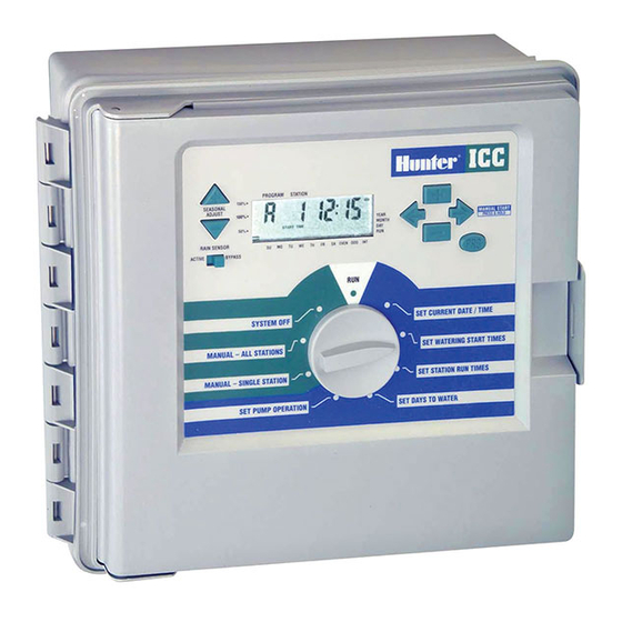
ICC
Commercial Irrigation Controllers
Owner's Manual and
Installation Instructions for
all 8 Station Base Models
ICC-800PL Plastic Cabinet
■
ICC-801PL Plastic Cabinet
■
(International)
ICC-800M Metal Cabinet
■
ICC-800SS
Stainless Steel Cabinet
■
ICC-800PP Plastic Pedestal
■
ICC-800SAT Field Satellite
■
Controllers for IMMS
TM
®
All STATIONS
SET PROGRAM
Advertisement
Table of Contents
Troubleshooting

Related Manuals for Hunter ICC-800PL


Summary of Contents for Hunter ICC-800PL
- Page 1 Commercial Irrigation Controllers Owner’s Manual and Installation Instructions for all 8 Station Base Models ICC-800PL Plastic Cabinet ■ ICC-801PL Plastic Cabinet ■ (International) ICC-800M Metal Cabinet ■ All STATIONS SET PROGRAM ICC-800SS Stainless Steel Cabinet ■ ICC-800PP Plastic Pedestal ■...
- Page 3 Connecting a Pump Start Relay ..................................15 Connecting a Weather Sensor (Not Included) ..............................16 Connecting an SRR or ICR Remote Control (Not Included) ..........................17 Connecting the Hunter Irrigation Management and Monitoring System™ (Not Included) ................. 18 Power Failures ......................................18 CONTROLLER PROGRAMMING AND OPERATION Sprinkler System Fundamentals ...................................
- Page 4 TABLE OF CONTENTS (continued)..................Programming Fundamentals ..................................22 Programming Fundamentals Examples ................................. 23 Programming the Controller ..................................24 Setting the Current Date and Time ................................25 Setting Program Start Time ..................................25 Eliminating a Program Start Time ................................26 Setting Station Run Times (Length of Watering for Each Area) ........................26 Setting Days to Water ....................................
-
Page 5: Introduction
Finally, there’s an affordable, full-featured indoor/outdoor controller for commercial applications. Hunter Industries is pleased to introduce the ICC – Institutional/Commercial Controller for commercial use. Designed with the needs of the customer in mind, the ICC offers simplified dial programming and an impressive range of features typically found in controllers that cost twice as much. -
Page 6: Icc Components
ICC COMPONENTS ........................ALL STATIONS PROGRAM... - Page 7 This section will give you a brief overview of some of the components 18. Rain Sensor Switch – Allows user to bypass weather sensor if one on the ICC. Each item will be discussed in further detail later, however is installed. this section can be helpful in getting acquainted with the different Buttons –...
-
Page 8: Icc Components
ICC COMPONENTS – WIRING CABINET ................9V Battery... - Page 9 D – Wiring Cabinet 20. 9-Volt Battery – The alkaline battery keeps time during power outages or if the transformer is disconnected. The user may also program the controller without AC power. 21. Reset Button – This button will restart the computer in case of power surge or display freezing.
-
Page 10: Mounting The Controller To Wall
MOUNTING THE CONTROLLER TO WALL ................Wall Mount for Plastic, Metal or Stainless Steel Cabinet ICC Controller All necessary hardware is included for most installations. Plastic Cabinet 1. Select a location as close as possible to a standard electrical outlet Cutaway View that is not controlled by a light switch. -
Page 11: Mounting The Controller (Icc Metal Pedestal)
MOUNTING THE CONTROLLER (ICC METAL PEDESTAL)..........Pedestal Mount, Metal or Stainless Steel Cabinet 1. Assemble the mounting template using the instructions provided with the pedestal. ICC Controller Metal Cabinet 2. Using the enclosed mounting template, locate the bolts two inches deep in the concrete pad, in the locations indicated. -
Page 12: Mounting The Controller (Icc-800Pp/Icc-800Sat)
MOUNTING THE CONTROLLER (ICC-800PP/ICC-800SAT)..........Plastic Pedestal Mounting 1. Set concrete forms using the installation instructions provided with the controller. Allow 2" of conduit above the surface of the concrete pad. 2. Assemble the mounting template. Twist one nut on each of the four J-bolts and slide each bolt through the template. -
Page 13: Connecting Valves
CONNECTING VALVES ......................1. Route valve wires between control valve location and controller. 2. At valves, attach a common wire to either solenoid wire of all valves. Valve Common Wire This is most commonly a white colored wire. Attach a separate control wire to the remaining wire of each valve. -
Page 14: Connecting Ac Power (Icc-800)
CONNECTING AC POWER (ICC-800) ..................Figure 1 – Junction Box without Terminal Strip (120 Volt) It is recommended that a licensed electrician perform the following power installation. 120 Black Wire (120 Volt) N Blue Wire (Neutral) 230 Brown Wire Green Wire (Use only for 230 Volt (Ground) Connections ) -
Page 15: Connecting Ac Power (Icc-801Pl And Icc-800M/Icc-800Ss)
CONNECTING AC POWER (ICC-801PL AND ICC-800M/ICC-800SS) ......Grounding The ICC 1. Remove the cover from junction box. 2. Strip ½" off of each wire. The ICC is equipped with built-in electrical surge protection. For this system to function properly, the earth ground terminal on the power 3. -
Page 16: Connecting Station Modules
CONNECTING STATION MODULES ..................The ICC controller is supplied with one factory-installed station module Note: The Positive-Lock™ feature was added for up to 8 stations. Additional modules may be added in increments of to ICM modules date coded 12/02 or newer. The 4 or 8 stations to expand the controller’s station capability (maximum modules will also work with older ICC units. -
Page 17: Connecting The Battery (Optional)
CONNECTING THE BATTERY (OPTIONAL)................Connect a 9-volt alkaline battery (not included) to the battery terminals and place in the battery compartment in the controller cabinet. The battery keeps time during power outages and allows the user to program the controller without AC power. Watering will not occur without AC power. -
Page 18: Connecting A Master Valve
CONNECTING A MASTER VALVE ..................Power Module NOTE: Complete this section only if you have Master Valve a master valve installed. A master valve is a Common Wire normally closed valve installed at the supply point of the main line that opens only when the automatic Master system is activated. -
Page 19: Connecting A Pump Start Relay
The controller should be mounted at least 15 feet (4.5 m) away from both the pump start relay and the pump. When a pump is to be operated by the controller, a pump start relay must be used. Hunter offers a full range a pump start relays for most applications. -
Page 20: Connecting A Weather Sensor (Not Included)
BYPASS position or install a short jumper wire between the sensor terminals. For more information on Mini-Clik sensors, visit Hunter's Web site at http://www.HunterIndustries.com or contact your local dealer. -
Page 21: Connecting An Srr Or Icr Remote Control (Not Included)
Power Module ® allowing for fast and easy use of the Hunter SRR or ICR remote control. The remote makes it possible for contractors and end users alike to operate a system without having to walk back and forth to the controller. -
Page 22: Power Failures
It’s able to team with any or all of the standard automatic controllers in the Hunter line-up, from the SRC to the Pro-C to the ICC. Plus, it’s a system that’s easy and affordable to upgrade, making it possible to accommodate an expanding network of controllers. -
Page 23: Sprinkler System Fundamentals
SPRINKLER SYSTEM FUNDAMENTALS................Valve 1 Valve 2 There are three main components that are involved with all automatic sprinkler systems that are made today. They are the controller, control valves, and the sprinklers. The controller is what makes the whole system operate efficiently. It is technically the brain of the entire system, instructing the valves when to supply water to the sprinklers and for how long to do so. -
Page 24: Creating A Watering Schedule
CREATING A WATERING SCHEDULE ................... For most consumers, it is much easier to plan your specific watering schedule onto paper before actually programming the information It is usually good to water one or two hours before into the controller. It’s also handy to have a written record of your sunrise. - Page 25 HUNTER ICC PROGRAM A PROGRAM B PROGRAM C PROGRAM D CALENDAR DAY SU MO TU WE TH FR SA SU MO TU WE TH FR SA SU MO TU WE TH FR SA SU MO TU WE TH FR SA...
-
Page 26: Programming Fundamentals
We realize that many consumers will have variations in their plant sequence one at a time. All that is required to create a watering program watering needs, so at Hunter we equipped the ICC with four different is to: programs: A, B, C, and D. These programs are completely independent of each other and give you the ability to have four coexisting timers in 1. -
Page 27: Programming Fundamentals Examples
PROGRAMMING FUNDAMENTALS EXAMPLE ..............HUNTER ICC PROGRAM A PROGRAM B Program A CALENDAR DAY SU MO TU WE TH FR SA SU MO TU WE TH FR SA Station 1 INTERVAL DAY 15 min. 1st Program ODD/EVEN DAY EVEN EVEN... -
Page 28: Programming The Controller
PROGRAMMING THE CONTROLLER ................... Two key features of the ICC that make programming a snap are its clear, NOTE: A basic programming rule is that whatever easy-to-read LCD display and its easy-to-use dial design. symbol or character is flashing will be the item The ICC display shows time and day when the controller is idle. -
Page 29: Setting The Current Date And Time
Setting The Current Date And Time Setting Program Start Time 1. Turn the dial to the SET 1. Turn the dial to the SET SET CURRENT DATE /TIME SET PROGRAM CURRENT DATE/TIME position. PROGRAM START TIMES START TIMES position. 2. The current year will be flashing in the display. -
Page 30: Eliminating A Program Start Time
PROGRAMMING THE CONTROLLER (continued) .............. Eliminating A Program Start Time Setting Station Run Times (Length of Watering for Each Area) With the dial set to the SET 1. Turn the dial to the SET PROGRAM START TIMES SET PROGRAM STATION RUN TIMES position. START TIMES position, push the 2. -
Page 31: Setting Days To Water
Selecting Specific Days of the Week to Water NOTE: If a station is assigned a run time on program 1. With the arrow cursor on a specific day (the cursor always starts A, B, or C, then that station cannot be assigned with Sunday), press the button to activate a particular day of the to Program D. -
Page 32: Selecting Interval Watering
INTERVAL sensors (the ICC works ACTIVE BYPASS designator. with the Hunter Mini-Clik ® plus some other rain, wind, 3. Press the button. The INTERVAL DAYS REMAINING and freeze sensors on the market today). If the system is preventing... -
Page 33: Manually Run A Single Station
Manually Run A Single Station 5. Use the button to move to the next station. 1. Turn the dial to the MANUAL- 6. Repeat steps 3 and 4 to customize each station if desired. SINGLE STATION position. 7. Press the button until desired starting station is displayed. -
Page 34: Seasonal Adjustment
PROGRAMMING THE CONTROLLER (continued) .............. Seasonal Adjustment Seasonal Adjust is used to make global run time changes without reprogramming the entire controller. This feature is perfect for making small changes that are necessary as the weather changes without reprogramming the entire controller. For instance, hotter times of the year may require a bit more water. -
Page 35: Advanced Programming Capabilities
ADVANCED PROGRAMMING CAPABILITIES..............Programmable Rain Off There are four advanced features available to customize the ICC to more complex watering requirements. Two of these features are “hidden” to This feature permits the user to SYSTEM OFF make accidentally programming them nearly impossible. stop all programmed waterings for a designated period from 1 to 7 Set Pump/Master Valve Operation... -
Page 36: Hidden Features
HIDDEN FEATURES ......................... 1. Start with the dial in the RUN position. NOTE: The hidden features described below can only be entered by starting with the dial in the RUN 2. Press and hold the button position and holding down various buttons while down while turning the dial to the knob is turned to various setup positions. - Page 37 Setting the Soak Times 1. Start with the dial in the RUN position. It is only necessary to set a SOAK time if the accumulated CYCLE times on any single program will not provide an adequate soak time. For 2. Press and hold the button instance, if the sum of the cycle times for all stations in a program down while turning the dial to...
-
Page 38: Hidden Features
3. After a 2 second pause, the test program will begin. user can run the Hunter Quick Check™ circuit test procedure. This circuit FREQUENTLY ASKED QUESTIONS ..................What Size Field Wiring Conduit Should I Use? -
Page 39: Troubleshooting Guide
TROUBLESHOOTING GUIDE ....................PROBLEM CAUSES SOLUTIONS The controller repeats itself or continu- Too many start times (user programming Only one start time per active program is ously watering even when it should not error). required. Refer to "Setting Program Start be on/controller cycles over and over. -
Page 40: Troubleshooting Guide
TROUBLESHOOTING GUIDE (continued) ................PROBLEM CAUSES SOLUTIONS The controller does not start Possible programming error. Check to make sure start time is entered automatically. correctly (note AM/PM setting as well). Check to make sure watering day is active. Rain sensor will not shut off system. Incorrect sensor type wired directly into sen- Make sure sensor is microswitch type such sor circuit. -
Page 41: Specifications
SPECIFICATIONS ........................Operating Specifications • Station Run Time: 1 minute to 2 hours (in 1-minute increments) on programs A, B, and C. Up to 12 hours on program D. The longer run time on program D is primarily to accommodate drip irrigation applications. - Page 44 Federal Communications Commission helpful: “How to Identify and Resolve Radio-TV Interference Problems.” This booklet is available from the U.S. Government Printing Office, Washington, D.C., Stock No. 004-000-00345-4 (price – $2.00 postpaid). Hunter Industries Incorporated • The Irrigation Innovators © 2005 Hunter Industries Incorporated 1940 Diamond Street •...