Hunter Pro-C Owner's Manual And Installation Instructions
Residential and light commercial irrigation controllers, indoor or outdoor versions
Hide thumbs
Also See for Pro-C:
- User manual ,
- Owner's manual and installation instructions (40 pages) ,
- Product information (36 pages)
Table of Contents
Advertisement
Pro-C
Residential and Light Commercial
Irrigation Controllers
Indoor or Outdoor Versions
Owner's Manual and
Installation Instructions
Please leave with property owner
®
RUN
RAIN SENSOR
BYPASS
ACTIVE
SYSTEM OFF
MANUAL – ALL
MANUAL – SINGLE
SET PUMP
Pro-C
SET CURRENT DATE / TIME
SET WATERING START TIMES
SET STATION RUN TIMES
SET DAYS TO WATER
Advertisement
Table of Contents

Related Manuals for Hunter Pro-C


Summary of Contents for Hunter Pro-C
- Page 1 Pro-C Residential and Light Commercial Irrigation Controllers Indoor or Outdoor Versions Owner’s Manual and Installation Instructions RAIN SENSOR Pro-C BYPASS ACTIVE SYSTEM OFF SET CURRENT DATE / TIME MANUAL – ALL SET WATERING START TIMES Please leave with property owner MANUAL –...
-
Page 3: Table Of Contents
Connecting a Pump Start Relay ..................................12 Connecting a Weather Sensor (Not Included) ..............................13 Connecting an SRR or ICR Remote Control (Not Included) ..........................14 Connecting to the Hunter Irrigation Management And Monitoring System™ ....................16 Power Failures......................................16 CONTROLLER PROGRAMMING AND OPERATION Sprinkler System Fundamentals ................................... - Page 4 TABLE OF CONTENTS (continued)..................Programming The Controller ..................................22 Setting the Current Date and Time ................................22 Setting Watering Start Times..................................23 Eliminating a Program Start Time ................................23 Setting Station Run Times (Length of Watering for Each Area) ........................24 Setting Days to Water ....................................
-
Page 5: Introduction
The Pro-C is so easy to use that you’ll need this user guide very little after installation. If you do have a question about the controller, refer to this booklet or to the abbreviated instructions inside the door. -
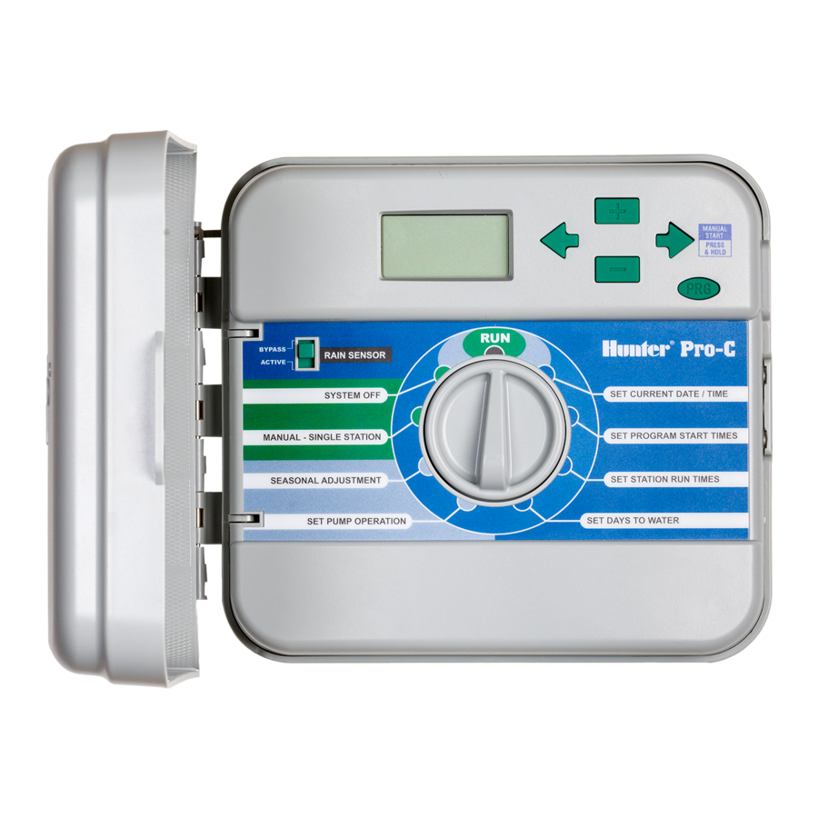
Page 6: Pro-C Components
PRO-C COMPONENTS......................RAIN SENSOR Pro-C BYPASS ® ACTIVE SYSTEM OFF SET CURRENT DATE / TIME MANUAL – ALL STATIONS SET WATERING START TIMES MANUAL – SINGLE STATION SET STATION RUN TIMES SET PUMP OPERATION SET DAYS TO WATER... - Page 7 This section will give you a brief overview of some of the components on Buttons – Used to increase or decrease the seasonal the Pro-C. Each item will be discussed in further detail later, however this adjust option. section can be helpful in getting acquainted with the controller.
-
Page 8: Pro-C Components - Wiring Cabinet
PRO-C COMPONENTS – WIRING CABINET................ �� �� �� �� �� �� �� ��... - Page 9 D. – Wiring Compartment 20. 9-Volt Battery – An alkaline battery (not included) allows you to program the controller without AC power. 21. Reset Button – This button will reset the controller. All programmed data will remain intact. 22. Power Area – Used to attach transformer, sensor wires, and other systems from their source to the controller.
-
Page 10: Mounting The Indoor Controller To A Wall
The location should be protected from moisture and direct sunlight. 2. Remove the front panel from the Pro-C by pulling down the hinge release. Removing the front panel will ease installation of the controller. -
Page 11: Mounting The Outdoor Controller To A Wall
2. Make sure to abide by all electrical and installation codes when attaching to an external wall. 3. Remove the front panel from the Pro-C by pulling down the hinge release. Removing the front panel will ease installation of the controller. -
Page 12: Connecting Valves And Ac Power
CONNECTING VALVES AND AC POWER ................1. Route valve wires between control valve location and controller. NOTE: It is usually best to connect all field wires 2. At valves, attach a common wire to either solenoid wire of all valves. prior to powering up the controller. - Page 13 NOTE: It is recommended that a licensed Valve 4 electrician perform the following power installation. Valve 3 Outdoor Cabinet Route AC power cable and conduit through the 1⁄2" (13 mm) conduit opening on the left side of the bottom of the cabinet.
-
Page 14: Connecting Station Modules
CONNECTING STATION MODULES ..................The Pro-C controller is designed with a simple to use Easy-Lock™ The Pro-C controller is supplied with a factory-installed base module feature that assures that the modules are firmly secured into the for up to 3 stations. Additional modules may be added in increments of 3 stations (PCM-300) or a single 9-station (PCM-900) to expand the controller. -
Page 15: Connecting The Battery (Optional)
CONNECTING THE BATTERY FOR PROGRAMMING WITHOUT AC POWER (OPTIONAL)..Connect a 9-volt alkaline battery (not included) to the battery terminals and place in the battery compartment in the controller cabinet. The battery allows the user to program the controller without AC power. Watering will not occur without AC power. Since this controller has non-volatile memory, the program clock and calendar will be retained during a power outage even if no battery is installed. -
Page 16: Connecting A Pump Start Relay
The controller should be mounted at least 15 feet (4.5 m) away from both the pump start relay and the pump. When a pump is to be operated by the controller, a pump start relay must be used. Hunter offers a full range a pump start relays for most applications. -
Page 17: Connecting A Weather Sensor (Not Included)
® NOTE: If the rain sensor switch is left in the ACTIVE sensor may be connected to the Pro-C. The purpose of this sensor is position and no sensor is connected and the jumper to stop watering when precipitation is sufficient. The sensor connects... -
Page 18: Connecting An Srr Or Icr Remote Control (Not Included)
3. Screw the SmartPort harness ® allowing for fast and easy use of the Hunter SRR, or Long Range ICR housing into the “Tee” as shown remote controls. The SRR and ICR make it possible for contractors and in Fig.1. - Page 19 For easiest installation, Receiver order a new Hunter SmartPort shielded cable wiring harness (part #SRR-SCWH) with a full 25 feet of shielded cable.
-
Page 20: Connecting To The Hunter Irrigation Management And Monitoring System
It’s able to team with any or all of the standard be handled directly at each site’s controller. Scheduling of days to water, automatic controllers in the Hunter line-up, from the SRC to the Pro-C to run times, start times, cycle and soak operations and more can now the ICC. -
Page 21: Sprinkler System Fundamentals
The valve controls a group of sprinklers called a watering station. These stations are laid out in a fashion according to the type of plant life that exists there, the locations of the plants, and the maximum amount Pro-C Controller Valve 1 Valve 2... -
Page 22: Programming Fundamentals
Program We realize that many consumers will have variations in their plant Ends at watering needs, so at Hunter we equipped the Pro-C with three different 6:50 programs A, B, and C. These programs are completely independent of each other and give you the ability to have three coexisting timers in... -
Page 23: Creating A Watering Schedule
CREATING A WATERING SCHEDULE ................... For most consumers, it is much easier to plan your specific watering NOTE: It is usually good to water one or two hours schedule onto paper before actually programming the information before sunrise. Water pressure will be at optimum into the controller. -
Page 24: Watering Schedule Form Example
WATERING SCHEDULE FORM (EXAMPLE) ................ HUNTER PRO-C PROGRAM A PROGRAM B PROGRAM C DAY OF THE WEEK ODD/ EVEN or INTERVAL Every 1 day Every 3 days Every 20 days 7:00 AM 9:00 AM 1:00 PM PROGRAM START TIMES STATION RUN TIME... -
Page 25: Watering Schedule Form
WATERING SCHEDULE FORM....................HUNTER PRO-C PROGRAM A PROGRAM B PROGRAM C DAY OF THE WEEK INTERVAL (Choose 1 to 31 days) PROGRAM START TIMES STATION RUN TIME STATION RUN TIME LOCATION STATION RUN TIME STATION NOTES:... -
Page 26: Programming The Controller
PROGRAMMING THE CONTROLLER ................... Setting the Current Date and Time Two key features of the Pro-C that make programming a snap are its clear, easy-to-read LCD display and its easy-to-use dial design. 1. Turn the dial to the SET The Pro-C display shows time and day when the controller is idle. -
Page 27: Setting Watering Start Times
NOTE: Regardless of the order in which the start times are entered, the Pro-C will always arrange the start times in chronological order when the dial is moved off the SET WATERING START TIMES position. -
Page 28: Setting Station Run Times (Length Of Watering For Each Area)
PROGRAMMING THE CONTROLLER (continued) .............. Setting Station Run Times (Length of Watering for Each Area) Setting Days to Water 1. Turn the dial to the SET 1. Turn the dial to the SET DAYS TO STATION RUN TIMES position. WATER position. 2. -
Page 29: Selecting Interval Watering
With this built-in feature, there is no need for an BYPASS additional manual bypass switch when using rain ACTIVE sensors (the Pro-C works with the Hunter Mini-Clik ® SYSTEM plus some other rain, wind, and freeze sensors on the market today). If the system is preventing system operation (or no sensor is installed and the switch is in the ACTIVE position), SENSOR OFF will be displayed. -
Page 30: Run
PROGRAMMING THE CONTROLLER (continued) .............. Manually Run All Stations After programming is complete, turn the dial to 1. Turn the dial to MANUAL-ALL RUN to enable automatic execution of all selected STATIONS. MANUAL – ALL STATIONS programs and start times. 2. -
Page 31: One Touch Manual Start And Advance
One Touch Manual Start and Advance Seasonal Adjustment Seasonal Adjust is used to make global run time changes without You can also activate all stations to water without using the dial. re-programming the entire controller. This feature is perfect for making 1. -
Page 32: Advanced Features
ADVANCED FEATURES ......................2) Programmable Rain Off There are three advanced features available to customize the Pro-C to more complex watering requirements. One of these features is “hidden” This feature permits the user to stop all SYSTEM OFF to make accidentally programming them nearly impossible. -
Page 33: Hidden Features
3) Setting Event Day(s) Off 4. Use the button until the cursor is at the day of the week you wish to set as a Programming in a No Water Day(s) is useful to inhibit watering No Water Day. on mowing days, etc. For instance, if you always mow the lawn on Saturdays you would designate Saturday as a No Water Day so you 5. - Page 34 2) Test Program buttons simultaneously. In the standby mode, the LCD will display all segments (helpful when troubleshooting display The Pro-C allows the user a simplified method for running a test problems). Press the button to begin the Quick Check test procedure.
-
Page 35: Troubleshooting Guide
TROUBLESHOOTING GUIDE ....................PROBLEM CAUSES SOLUTIONS There is no display. Check AC power wiring. Correct any errors. The display reads “ERR”. Electrical noise is entering the system. Check the SmartPort wiring harness. If ® the wires were extended then they will need to be replaced with shielded cable. - Page 36 TROUBLESHOOTING GUIDE (continued) ................PROBLEM CAUSES SOLUTIONS Rain sensor will not shut off system. Make sure sensor is micro-switch type such Incompatible rain sensor or the jumper was not removed when sensor was installed. as Mini-Clik (Rain Bird Rain Check is not ®...
-
Page 37: Frequently Asked Questions
FREQUENTLY ASKED QUESTIONS ..................WHAT SIZE FIELD WIRING CONDUIT SHOULD I USE? Locate the size conduit across the top and the wire size along the side. Where the two intersect on the table tells you approximately how many wires will fill the conduit. CONDUIT SIZES Wire Size 3⁄4"... -
Page 38: Specifications
SPECIFICATIONS ........................Operating Specifications Default Settings • Station Run Time: 1 minute to 6 hours on programs A, B, and C. All stations are set to zero run time. This controller has a non-volatile memory that retains all entered program data even during power •... - Page 39 INFORMATION ABOUT YOUR SPRINKLER SYSTEM............Date of Installation: _________________________________________________________________________________________ Contractor Installing System:__________________________________________________________________________________ Address:__________________________________________________________________________________________________ _________________________________________________________________________________________________________ Phone: ___________________________________________________________________________________________________ Location of Control Valves: ___________________________________________________________________________________ _________________________________________________________________________________________________________ Location of Weather Sensor: __________________________________________________________________________________ _________________________________________________________________________________________________________ Location of Main Water Supply Shutoff: _________________________________________________________________________...
-
Page 40: Fcc Notice
Federal Communications Commission helpful: “How to Identify and Resolve Radio-TV Interference Problems.” This booklet is available from the U.S. Government Printing Office, Washington, D.C., Stock No. 004-000-00345-4 (price – $2.00) Hunter Industries Incorporated • The Irrigation Innovators © 2003 Hunter Industries Incorporated 1940 Diamond Street •...