Advertisement
Power Supply Assembly and Installation Instructions
1 Overview
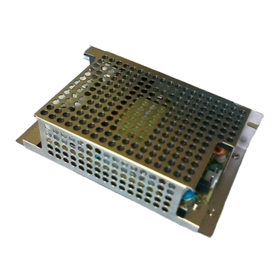
The PRO32E1PS and PW6K2E2PS power supply and battery charger is compatible with the PW3000,
PW5000, PW6000, PRO2200, and PRO3200 systems. For ordering purposes please use the PW6K2E2PS
for the PW3000, PW5000, and PW6000 systems and PRO32E1PS for PRO2200, and PRO3200 systems.
This power supply will convert AC input voltage into a 13.8VDC output with 4.0 amps maximum of
continuous current. The power supply accepts an input voltage of 85VAC to 265VAC at 50Hz/60Hz. The
power supply provides AC fail and low battery supervision when connected to PW3000, PW5000,
PW6000, PRO2200, and PRO3200 I/O PFL (Power Fail) and auxiliary inputs.
2 Specifications
•
4.0 amp maximum continuous output current at 13.8VDC with overload protection.
•
Filtered and electronically regulated outputs.
•
Built-in charger for sealed lead acid batteries with a maximum charge current of 250mA.
•
Automatic switch over to stand-by battery, if present, upon AC power failure.
•
Reverse battery polarity with a non-replaceable fuse.
•
Low battery supervision when connected to a low battery input on the panel.
•
AC fail supervision when connected to PWR fail on panel.
•
Short circuit/overload/overvoltage protection.
•
0° C to 49° C operating temperature range.
•
UL 60950 listed.
•
CE compliant.
Warning
• Power Supply shall be installed in accordance with the National Electric Code, as
well as all applicable local regulations.
• Before installation, turn off the extra circuit breaker that supplies power to the
system. Do not re-apply power until installation is complete.
• To reduce the risk of electric shock, do not expose the unit to rain, liquids, or
excessive moisture.
1 of 12
Advertisement
Table of Contents

Related Manuals for Honeywell PRO32E1PS


Summary of Contents for Honeywell PRO32E1PS
-
Page 1: Specifications
Power Supply Assembly and Installation Instructions 1 Overview The PRO32E1PS and PW6K2E2PS power supply and battery charger is compatible with the PW3000, PW5000, PW6000, PRO2200, and PRO3200 systems. For ordering purposes please use the PW6K2E2PS for the PW3000, PW5000, and PW6000 systems and PRO32E1PS for PRO2200, and PRO3200 systems. -
Page 2: Pin Connectors
The power supply has three pin connectors (CN1, CN2, and CN3) to which you need to connect three cable assemblies, as shown below: 3 Pin Connectors Figure 1: Power Supply Pin Connectors Document 800-08279, Revision A 2 of 12 © Honeywell International. All rights reserved. February 2011... - Page 3 Connects to AC Power Inlet Figure 2: AC Power Inlet and LED Indicator Cable Assembly Connects to Figure 3: 12VDC Power and Battery Cable Assembly Document 800-08279, Revision A 3 of 12 © Honeywell International. All rights reserved. February 2011...
- Page 4 After connecting the three cable assemblies to the pin connectors CN1, CN2, and CN3, the fully connected power supply should look like the below photo (Figure 5 on page 5) when viewed from the front, inside the metal cabinet: Document 800-08279, Revision A 4 of 12 © Honeywell International. All rights reserved. February 2011...
-
Page 5: Installation Instructions
Figure 5: Fully Connected Power Supply, Front View 5 Installation Instructions 1. Use this power supply only with Honeywell PW3000, PW5000, PW6000, PRO2200, and PRO3200 series access control and proprietary alarm units. 2. Secure enclosure in the desired location, using appropriately sized fasteners. -
Page 6: Ac Input Connector
7. Slide the power supply down in the keyholes until they bottom out. Then, tighten the four mounting screws to secure the power supply to the metal plate. Document 800-08279, Revision A 6 of 12 © Honeywell International. All rights reserved. February 2011... - Page 7 Note: LED MUST be installed BEFORE the power inlet. 10. Once the LED is installed and fully seated, install the AC power inlet into the panel. See the photo below:. Power Inlet Document 800-08279, Revision A 7 of 12 © Honeywell International. All rights reserved. February 2011...
- Page 8 CN2: CN2 Pin Connector 12VDC Power and Battery Cable Connecting to CN2 Figure 7: 12VDC Power and Battery Cable Assembly Connecting to CN2 Pin Connector Document 800-08279, Revision A 8 of 12 © Honeywell International. All rights reserved. February 2011...
-
Page 9: Pin Connector
AC and Battery Fail Cable Connecting to CN3 This is how the pin connectors CN2 and CN3 should look like after attaching both cables: CN2 and CN3 connected Document 800-08279, Revision A 9 of 12 © Honeywell International. All rights reserved. February 2011... - Page 10 24. Check to make sure that the red LED located near the AC power inlet is illuminated. 25. Route all power-limited wiring at least 0.25” (6.35 mm) away from any non-power-limited wiring. Document 800-08279, Revision A 10 of 12 © Honeywell International. All rights reserved. February 2011...
- Page 11 26. Secure and lock the cabinet door to prevent access by unauthorized persons. 6 Connector Layout and Cabling Information 12VDC Power Battery Power Inlet Battery Fail Document 800-08279, Revision A 11 of 12 © Honeywell International. All rights reserved. February 2011...
- Page 12 Open AC OK Battery Fail Black Open Batt OK Battery Fail White Open Batt OK Table 3: Cable Assembly AC and Battery Fail Connections, CN3 Document 800-08279, Revision A 12 of 12 © Honeywell International. All rights reserved. February 2011...