
Related Manuals for Honeywell Notifier ACPS-610/E


Summary of Contents for Honeywell Notifier ACPS-610/E
- Page 1 Addressable Charger/ Power Supply ACPS-610/E Manual Document 53018 07/31/2007 Rev: P/N 53018:A1 ECN 07-166...
- Page 2 Fire Alarm System Limitations While a fire alarm system may lower insurance rates, it is not a substitute for fire insurance! An automatic fire alarm system—typically made up of Heat detectors do not sense particles of combustion and smoke detectors, heat detectors, manual pull stations, audible alarm only when heat on their sensors increases at a predeter- warning devices, and a fire alarm control panel with remote mined rate or reaches a predetermined level.
- Page 3 Acclimate® Plus™, HARSH™, NIS™, Notifier Integrated Systems™, NOTI•FIRE•NET™, and ONYXWorks™ are all trademarks; and FlashScan®, NION®, NOTIFIER®, ONYX®, SpectrAlert®, UniNet®, VeriFire®, and VIEW® are all registered trademarks of Honeywell International Inc. Echelon® is a registered trademark and LonWorks™ is a trademark of Echelon Corporation. ARCNET® is a registered trademark of Datapoint Corporation. Microsoft®...
- Page 4 Brief description of content you think should be improved or corrected • Your suggestion for how to correct/improve documentation Send email messages to: FireSystems.TechPubs@honeywell.com Please note this email address is for documentation feedback only. If you have any technical issues, please contact Technical Services. ACPS-610/E Manual — P/N 53018:A1 07/31/2007...
-
Page 5: Table Of Contents
Table of Contents Section 1: Introduction......................7 1.1: Features................................7 1.2: Specifications..............................7 1.2.1: KAPS-24/E Power Supply Board......................7 1.2.2: Main Control Unit ..........................8 1.3: Installation Standards and Codes........................8 1.3.1: UL 9th Edition Compliance.........................9 1.4: Related Documentation ..........................10 1.5: Notes, Cautions, and Warnings........................10 1.6: Board Layout ...............................11 1.7: LED Indicators.............................12 Section 2: Installation...................... - Page 6 Table of Contents Section 4: Applications ......................39 4.1: NAC Outputs ...............................39 4.2: Power Outputs..............................39 4.3: Style B (Class B) Initiating Device Circuit....................40 4.4: Synchronization ............................40 Section 5: Power Supply Calculations ................. 45 5.1: DC Current Draw Calculations ........................45 5.1.1: Calculating the Maximum Secondary Power Non-Fire Alarm Current Draw ........48 5.1.2: Calculating the Maximum Secondary Power Fire Alarm Current Draw ..........48 5.2: Calculating the Battery Requirements ......................49 5.2.1: Calculating the Battery Capacity .......................49...
-
Page 7: Section 1: Introduction
Section 1: Introduction The ACPS-610/E is an addressable power supply and battery charger with 24 VDC outputs. It operates in FlashScan® or CLIP (Classic Interface Protocol) mode, and has built-in strobe synchronization. Its four outputs may be independently configured to drive Notification Appliance Circuits (NACs--constant, coded, or synchronized) or to provide auxiliary power (resettable, door holder, or general purpose). -
Page 8: 2: Main Control Unit
Introduction Installation Standards and Codes Utilizes wire sizes 10-14 AWG. (5.26 mm. – 2.08 mm. Charging current: 2.0 A, 5.0 A, or OFF (Software selectable) Based on battery size programming. Charging voltage: 27.6 VDC (nominal) To calculate expected standby operating times, see Section 5.2 on page 49. Battery Fuse - (F2) 15A, Slo-Blow Fuse P/N 12057 1.2.2 Main Control Unit... -
Page 9: 1: Ul 9Th Edition Compliance
Installation Standards and Codes Introduction In addition, the installer should be familiar with the following standards: • NEC Article 300 Wiring Methods • NEC Article 760 Fire Protective Signaling Systems • Applicable Local and State Building Codes • Requirements of the Local Authority Having Jurisdiction •... -
Page 10: Related Documentation
Introduction Related Documentation 1.4 Related Documentation To obtain a complete understanding of specific features of the ACPS-610, or to become familiar with functions in general, make use of the documentation listed in Table 1.1. Title Document Number AFP-100 Instruction Manual 51010 AFP-200 Instruction Manual 15511... -
Page 11: Board Layout
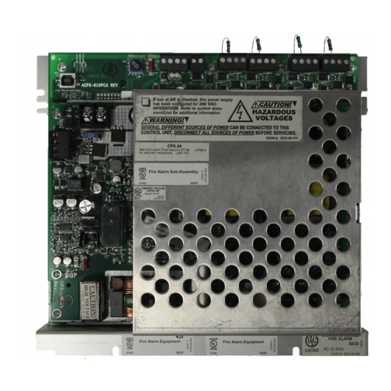
Board Layout Introduction 1.6 Board Layout The ACPS-610 is comprised of two boards; the main control unit (the larger rear board), and the KAPS-24/E power supply (the smaller front board). Figure 1.1 below illustrates the layouts for these boards. Figure 1.2 illustrates the positions of the LEDs. OUTPUT 3 –... -
Page 12: Led Indicators
Introduction LED Indicators 1.7 LED Indicators There are 21 LEDs that indicate various conditions and troubles. The following table lists and describes each. Figure 1.2 on page 13 shows the location of the LEDs on the PC boards. Reference LED Name Color Description STATUS... - Page 13 LED Indicators Introduction Figure 1.2 Locations of LED Indicators ACPS-610/E Manual — P/N 53018:A1 07/31/2007...
-
Page 14: Section 2: Installation
Section 2: Installation WARNING: High Voltages Present! Use extreme caution when working with the ACPS-610. High voltage and AC line-connected circuits are present in this power supply. Turn off and remove all power sources. To reduce the risk of electric shock, make sure to properly ground the ACPS-610. Install the snap-on cover for TB1 after wiring. -
Page 15: 2: In A Cab-4 Series Backbox
Mounting Options Installation The ACPS-610 can fit in either the lower left or lower right of any CAB-4 Series cabinet. Lower left installation: Lower the power supply over the cabinet’s support brackets and fasten to the backbox with two # 4-40 self- threading screws, included,... -
Page 16: 3: In A Bb-25 Cabinet
Installation Mounting Options 2.1.3 In a BB-25 Cabinet The ACPS-610 mounts in the left side of a BB-25 cabinet. Two 26 amp-hour batteries fit into the right side of the cabinet. A BB-100 or BB-200 cabinet is required for batteries larger than 26 amp- hour. -
Page 17: 5: In A Bb-200 Cabinet
UL Power-limited Wiring Requirements Installation 2.1.5 In a BB-200 Cabinet Fasten the ACPS-610 chassis to the backbox using the two # 4-40 keps nuts, included, (P/N 36045) at these positions. Figure 2.6 BB-200 Mounting The ACPS-610 mounts in a BB-200 cabinet with four 100 amp-hour batteries (two on the top shelf and two on the bottom). - Page 18 Installation UL Power-limited Wiring Requirements Terminal block and pin connections are illustrated in Figure 1.1. SLC and Output Circuit Wiring: TB3: Power-limited, regulated, and filtered. Supervised Nonpower-limited except for TB1: UZC+, UZC–. and supervised Outputs 1-4 supervised in NAC configuration only. TB1: AC Primary Power Wiring - Nonpower-limited...
-
Page 19: Connecting The Power Supply To Ac Power
Connecting the Power Supply to AC Power Installation WARNING: Risk of electrical shock! Remove all power sources to equipment while connecting electrical components. Leave the external, main power breaker OFF until installation of the entire system is complete. WARNING: Risk of equipment damage! Several sources of power can be connected to the control panel and/or power supply. -
Page 20: Installing And Connecting The Batteries
Installation Installing and Connecting the Batteries 2.4 Installing and Connecting the Batteries WARNING: Risk of severe burns! Batteries contain sulfuric acid which can cause severe burns to the skin and eyes, and can destroy fabrics. If contact is made with sulfuric acid, immediately flush skin or eyes with water for 15 minutes and seek immediate medical attention. -
Page 21: 3: Connecting The Power Supply To Four Batteries
Installing and Connecting the Batteries Installation Connect another cable from TB3 ( -) on the power supply to the negative (–) terminal BATT IN of the other battery. Only after initial system power-up, connect a battery interconnect cable between the negative (-) terminal on the first battery to the positive (+) terminal on the second battery. -
Page 22: 4: Connecting Multiple Power Supplies (Separate Batteries)
Installation Installing and Connecting the Batteries 2.4.4 Connecting Multiple Power Supplies (Separate Batteries) This application may be used when you want a single power supply to monitor for ground fault for multiple power supplies. Follow these guidelines when connecting multiple power supplies: •... -
Page 23: 5: Connecting Multiple Power Supplies (One Set Of Batteries)
Installing and Connecting the Batteries Installation 2.4.5 Connecting Multiple Power Supplies (One Set of Batteries) Certain system designs may require connecting multiple power supplies to one set of batteries. Follow these guidelines when connecting multiple power supplies: • For proper supervision, enable only the charger directly connected to the batteries. Disable all other chargers. -
Page 24: Ups Trouble Connections
Installation UPS Trouble Connections 2.5 UPS Trouble Connections When a UPS is required, use a monitor module with a trouble Type ID to convey a trouble signal to the FACP. SLC to panel or next device SLC from To normally panel or closed UPS previous... - Page 25 Notes ACPS-610/E Manual — P/N 53018:A1 07/31/2007...
-
Page 26: Section 3: Configuration And Programming
Section 3: Configuration and Programming 3.1 SLC Addressing When the ACPS-610 communicates via the SLC, the installer must reserve sequential SLC addresses (an address block) equal to the number of addresses that will be consumed by the ACPS-610. Determining the size of the address block and setting the SLC base address is described in this section. -
Page 27: 2: Setting The Base Address
SLC Addressing Configuration and Programming 3.1.2 Setting the Base Address The base address is the first address used in an SLC address block. Combine the SLC Address rotary switch (SW2) and slider switch (SW3) settings to determine the base address (B). The base address will be a number that ends in zero or five and the rest of the address block will progress sequentially from that number until all the addresses in the block are consumed. -
Page 28: Programming The Acps-610
Configuration and Programming Programming the ACPS-610 Figure 3.1 below gives two examples of setting the base address with both rotary and slider switch settings. SLC ADDRESSES BASE SELECTED ROTARY SLIDER SWITCH ADDRESS with maximum SWITCH POSITION fourteen ACPS-610 SETTING 005-018 120-133 Figure 3.1 SLC Address Selection 3.2 Programming the ACPS-610... -
Page 29: 2: Establishing The Hardware Connection
Programming the ACPS-610 Configuration and Programming Windows XP Professional with SP2 Windows 2000 with SP4 On the Found New Hardware Wizard window, select “No, On the Found New Hardware Wizard window, click Next. not this time”. Click Next. Select “Search for a suitable driver for my device”. Click Select “Install from a list or specific location”. -
Page 30: 4: Working Online
Configuration and Programming Programming the ACPS-610 3.2.4 Working Online NOTE: Start the PK-PPS utility before connecting to the power supply. In addition to creating and opening databases on your local drive, you may modify any ACPS-610 that is directly connected to your PC with the PK-PPS programming utility. When you are in the program and you are connected via the USB to a power supply, that power supply is represented by the icon in the left window. - Page 31 Programming the ACPS-610 Configuration and Programming Figure 3.4 PK-PPS: Label Label For greater ease of identification, you may create a label for each power supply. Labels may have a maximum of 40 characters. Figure 3.5 PK-PPS: Battery Charger Battery Charger Choose the appropriate battery charger current for the system’s battery capacity.
-
Page 32: 7: Output Configuration
Configuration and Programming Programming the ACPS-610 3.2.7 Output Configuration Output circuits one through four can be programmed independently with these worksheets. Each output may be configured as either a NAC, a power circuit, or a door holder. PK-PPS_NACOut.jpg Figure 3.6 PK-PPS: Output Configuration NOTE: Active NACs will disable the power supply’s charger. -
Page 33: 8: Global Settings
Programming the ACPS-610 Configuration and Programming 3.2.8 Global Settings Figure 3.7 PK-PPS: Coding Type Coding Type Code type is a global setting that applies to all NAC outputs configured as . (See ODED Section 3.2.6 on page 30.) NAC codes can be generated internally or they can come from an external source via the power supply’s UZC sync input (TB1). - Page 34 Configuration and Programming Programming the ACPS-610 Figure 3.8 PK-PPS: Synchronization Synchronization Select the protocol for synchronized outputs. Select , when the (UZC) XTERNAL power supply will be connected (via TB1) to an external sync source.The external sync source must be an FACP or power supply manufactured by the same manufacturer as the ACPS-610. This is a non-supervised connection.
- Page 35 Programming the ACPS-610 Configuration and Programming Figure 3.9 PK-PPS: Trouble Reporting Trouble Reporting Select the trouble reporting option. When the power supply is configured for US trouble reporting options, the panel will report a trouble message at the base address. Choose a US AC Fail Delay time ( , or ) from the drop-down menu.
-
Page 36: Configuring The Facp
Configuration and Programming Configuring the FACP 3.3 Configuring the FACP 3.3.1 Software Type ID Codes ACPS-610 points must be programmed at the FACP with Software Type ID codes. Refer to the panel programming manual for specific Software Type ID codes. Table 3.3 below gives general categories of codes that may be used for the AFP-100, AFP-200, AFP-300/400, AFC-600, AM2020/AFP-1010 FACPs. -
Page 37: 2: Two Stage Panel Programming
Two Stage Alert/Evacuation (Canada Only) Configuration and Programming If the output is a synchronized NAC, activating the first associated address turns the output on. If the output is a Door Holder, activating the first address turns the output off (instantly, in 30 seconds, or never –... - Page 38 Configuration and Programming Two Stage Alert/Evacuation (Canada Only) The sequence of operations is as follows. • A general alarm activates FCM L1M1 (Type code APND). • L1M2, which has been programmed via CBE for OR(L1M1), activates (Type code FORC). • L1M3 (Type code NONA) physically monitors L1M2 contacts.
-
Page 39: Section 4: Applications
Section 4: Applications 4.1 NAC Outputs Use listed end-of-line resistor, P/N ELR-2.2K, (included) to terminate Style Y (Class B) NAC. ELRs are not be used when Style Z (Class A) return is wired. Note: The NAC outputs shown above are in a non-coded configuration. Figure 4.1 Four NAC Outputs NOTE: Active NACs will disable the power supply’s charger. -
Page 40: Style B (Class B) Initiating Device Circuit
Applications Style B (Class B) Initiating Device Circuit 4.3 Style B (Class B) Initiating Device Circuit UL listed power supervision relay (shown in energized state) End-of-Line Resistor 47K Four-wire smoke detector Four-wire smoke detector SLC from SLC to next last device device Resettable 24 VDC power... - Page 41 Synchronization Applications Refer to the following figures for application illustrations. acps-610_Sync.cdr Figure 4.4 Supervised Parallel Master/Slave Synchronization Connections ACPS-610/E Manual — P/N 53018:A1 07/31/2007...
- Page 42 Applications Synchronization ACPS-610_UZC.cdr Figure 4.5 Supervised Synchronization Wiring Using UZC-256 ACPS-610/E Manual — P/N 53018:A1 07/31/2007...
- Page 43 Synchronization Applications ACPS-610_parallel.cdr To next floor Up to 50 power supplies ACPS-610 ACPS-610 Notification Zone Notification Zone THIRD FLOOR Up to 50 power supplies ACPS-610 ACPS-610 Notification Zone Notification Zone SECOND FLOOR Sync Riser From FACP or last ACPS-610 ACPS-610 device Notification Zone Notification Zone...
- Page 44 Notes ACPS-610/E Manual — P/N 53018:A1 07/31/2007...
-
Page 45: Section 5: Power Supply Calculations
Section 5: Power Supply Calculations Calculations must be done to determine standby and alarm DC current loads. Ampere-hour requirements must be calculated as well to determine battery size. In the following section, the term “secondary” refers to the ACPS-610’s backup batteries: the term “primary”... - Page 46 Power Supply Calculations DC Current Draw Calculations OUTPUT 2 COLUMN A COLUMN B Standby Current (amps) Alarm Current (amps) ATEGORY X current draw= Total X current draw= Total Power Supervision Relays (EOLR-1) 4-Wire Smoke Detectors 4-Wire Smoke Detectors Annunciators Auxiliary Devices Auxiliary Devices Auxiliary Devices Notification Appliances...
- Page 47 DC Current Draw Calculations Power Supply Calculations OUTPUT 4 COLUMN A COLUMN B Standby Current (amps) Alarm Current (amps) ATEGORY X current draw= Total X current draw= Total Power Supervision Relays (EOLR-1) 4-Wire Smoke Detectors 4-Wire Smoke Detectors Annunciators Auxiliary Devices Auxiliary Devices Auxiliary Devices Notification Appliances...
-
Page 48: 1: Calculating The Maximum Secondary Power Non-Fire Alarm Current Draw
Power Supply Calculations DC Current Draw Calculations 5.1.1 Calculating the Maximum Secondary Power Non-Fire Alarm Current Draw Use the table below to determine the maximum current requirements of the secondary power source during non-fire alarm, standby conditions. The result obtained is the amount of current that the batteries must be able to supply to the fire alarm system. -
Page 49: Calculating The Battery Requirements
Calculating the Battery Requirements Power Supply Calculations 5.2 Calculating the Battery Requirements 5.2.1 Calculating the Battery Capacity Use this table to determine the battery capacity needed for the system: Current (amps) Time (hours) Required _________AH Secondary Non-Fire Required Standby Time (hours) Alarm (Standby) Current (from Table 5.6) ________________... -
Page 50: 2: Calculating The Battery Size
Power Supply Calculations Calculating the Battery Requirements 5.2.2 Calculating the Battery Size Use this table to choose the battery size, in amp-hours, needed to support the fire alarm system. The ACPS-610 can charge batteries from 12 to 200 AH. Select batteries that meet or exceed the Total Amp-Hours calculated in Table 5.8 and that are within the acceptable battery charger range. - Page 51 Notes ACPS-610/E Manual — P/N 53018:A1 07/31/2007...
- Page 52 Power Supply Calculations Calculating the Battery Requirements ACPS-610/E Manual — P/N 53018:A1 07/31/2007...
- Page 53 Index Numerics 2.2K ohm end-of-line resistor 41 DR-PS1 14 24VDC 45 resettable 40 47K ohm end-of-line resistor 40 Electronic Signal Silence virtual address 26 AC loss detection, delay 7 AC Power 7 FlashScan® 7 ACPS-2406 replacement 14 FMM-1 40 Address block 26 address block 26 address decade 27 Addressing 26...
- Page 54 P–W Index coded 7 non-coded 7 Temporal Pattern 36 Output applications 39 Trouble Reporting 35 T-tapping 41 Two Stage 36 Control-by-event (CBE) programming 37 Panel Programming 36 Output circuits set to coded NAC 36 Panel Programming Requirements Panel Programming 37 Software Type ID Codes 36 sequence of operations 38 Power 7...
- Page 55 This warranty is void if the product is altered or repaired by anyone other than Honeywell International Inc. or as expressly authorized by Honeywell International Inc.
- Page 56 World Headquarters 12 Clintonville Road Northford, CT 06472-1610 USA 203-484-7161 fax 203-484-7118 www.notifier.com...