Piusi K24 Calibration Manual
Elictronic turbine meter - pulser
Hide thumbs
Also See for K24:
- Installation, use & maintenance manual (24 pages) ,
- Use, maintenance and installation manual (2 pages) ,
- Use and maintenance manual (2 pages)
Advertisement
Quick Links
Menu
ENGLISH
INDEX
C.5
PACKAGE CONTENTS/PRE-INSPECTION
A
DECLARATION OF CONFORMITY
FOREWORD
To open the packaging, use a pair of scissors or a cutter, being careful
B
GENERAL WARNINGS
C
SAFETY INSTRUCTIONS
not to damage the dispensing system or its components.
C.1
SAFETY WARNINGS
NOTE
In the event that one or more of the components de-
C.2
FIRST AID RULES
scribed below are missing from inside the package,
C.3
GENERAL SAFETY RULES
C.4
PACKAGING
please contact Piusi inc technical support.
C.5
PACKAGE CONTENTS/PRE-INSPECTION
WARNING
Check that the data on the plate correspond to the
D
BECOMING ACQUAINTED WITH K24
D.1
COMPATIBLE LIQUIDS
desired speci cations. In the event of any anomaly,
D.2
DISPLAY LCD
contact the supplier immediately, indicating the nature
D.3
DISPLAY POSITIONING (METER VERSION ONLY)
of the defects. Do not use equipment which you suspect
D2
USERS BUTTONS
E
OPERATING MODES
might not be safe.
F
INSTALLATION
G
DAILY USE
G.1
DISPENSING IN NORMAL MODE
D
BECOMING ACQUAINTED WITH K24
G.1.1
PARTIAL RESET (NORMAL MODE)
G.1.2
RESETTING THE RESET TOTAL
G.2
DISPENSING WITH FLOW RATE MODE DISPLAY
FOREWORD
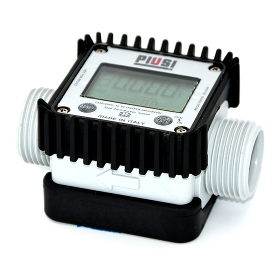
Electronic digital meter featuring a turbine measurement system, de-
G.2.1
PARTIAL RESET (FLOW RATE MODE)
signed for precise measuring of low viscosity uids.
H
CALIBRATION
K24 is available in 2 versions:
H1
DEFINITIONS
H2
CALIBRATION MODE
1
METER – with LCD display and calibration buttons
H.2.1
DISPLAY OF CURRENT CALIBRATION FACTOR AND
2
PULSER – single-channel impulse, cannectable with a remote display.
RESTORING FACTORY FACTOR.
H.2.2
IN FIELD CALIBRATION
Two big groups are suitable for its use:
H.2.2.1
IN-FIELD CALIBRATION PROCEDURE
With body made of inconductive plastic material of light colour,
A
H.2.3
DIRECT MODIFICATION OF K FACTOR
divided into high ow rate versions and low ow rate versions, with
I
METER CONFIGURATION
L
MAINTENANCE
stainless steel F/F bushing
M
MALFUNCTIONS
B
With body made of conductive plastic material of dark colour with
N
DISPOSAL
galvanized steel bushing
O
DATI TECNICI / TECHNICAL DATA
ow rate values
P
EXPLODED VIEWS AND OVERALL DIMENSIONS
D.1
COMPATILE LIQUIDS
A
DECLARATION OF CONFORMITY
The turbine is placed inside a hole through the body of k24, tted
Turbine
The undersigned:
with M-M threaded inlet and outlet. The supplied F-F bushing enables
measurement
PIUSI S.p.AVia Pacinotti 16/A z.i.Rangavino
several combinations of threads. K24 HAS 2 RUBBER PROTECTIONS,
system
46029 Suzzara - Mantova - Italy
DESIGNED TO ACT AS GASKETS TOO.
The liquids compatible with k24 are at low viscosity, namely:
HEREBY STATES
body made of incon-
Water
under its own responsibility, that the equipment described below:
ductive plastic material
Descriprion: METER
Aus 32 (D.E.F., Ad-Blue)
of light colour
Model: K24
Milk not suitable for human consumption
6HULDO QXPEHU
UHIHU WR /RW 1XPEHU VKRZQ RQ &( SODWH DI¿[HG WR SURGXFW<HDU RI
body made of conduc-
Diesel fuel
PDQXIDFWXUH
UHIHU WR WKH \HDU RI SURGXFWLRQ VKRZQ RQ WKH &( SODWH DI¿[HG WR WKH
tive plastic material of
Windscreen
SURGXFWLV LQ FRQIRUPLW\ ZLWK WKH OHJDO SURYLVLRQV LQGLFDWHG LQ WKH GLUHFWLYHV
dark colour
(OHFWURPDJQHWLF &RPSDWLELOLW\ 'LUHFWLYH (&
Main components: K24 Meter
7KH GRFXPHQWDWLRQ LV DW WKH GLVSRVDO RI WKH FRPSHWHQW DXWKRULW\ IROORZLQJ PRWLYDWHG
1
LCD display
UHTXHVW DW 3LXVL 6S$ RU IROORZLQJ UHTXHVW VHQW WR WKH HPDLO DGGUHVV
GRFBWHF#
2
RESET key
SLXVLFRP7KH SHUVRQ DXWKRULVHG WR FRPSLOH WKH WHFKQLFDO ¿OH DQG GUDZ XS WKH GHFOD-
3
CAL key
UDWLRQ LV 2WWR 9DULQL DV OHJDO UHSUHVHQWDWLYH
4
F-F bushing
1
Otto Varini
6X]]DUD
2
OHJDO UHSUHVHQWDWLYH
3
B
GENERAL WARNINGS
Important
To ensure operator safety and to protect the pump from po-
precautions
tential damage, workers must be fully acquainted with this
instruction manual before performing any operation.
Symbols used
The following symbols will be used throughout the manual
to highlight safety information and precautions of particular
in the manual
D.2
DISPLAY LCD
importance:
ATTENTION
FOREWORD
The "LCD" of the METER features two numerical registers and various
This symbol indicates safe working practices for opera-
indications displayed to the user only when the applicable function
tors and/or potentially exposed persons.
so requires.
WARNING
1
Partial register (5 gures with moving
This symbol indicates that there is risk of damage to the
comma FROM 0.1 to 99999) indicating
equipment and/or its components.
the volume dispensed since the reset
button was last pressed
NOTE
This symbol indicates useful information.
2
Indication of battery charge
Manual pres-
his manual should be complete and legible throughout. It
ervation
should remain available to end users and specialist installation
3
Indication of calibration mode
and maintenance technicians for consultation at any time.
Reproduction
All reproduction rights are reserved by Piusi S.p.A. The text
4
Totals register (6 gures with moving
cannot be reprinted without the written permission of Piusi
comma FROM 0.1 to 999999), that can
rights
S.p.A.
indicate two types of Total:
THIS MANUAL IS THE PROPERTY OF Piusi S.p.A.
4.1. General Total that cannot be reset (TOTAL)
ANY REPRODUCTION, EVEN PARTIAL, IS FORBIDDEN.
4.2. Resettable total (Reset TOTAL)
5
Indication of total multiplication factor
C
SAFETY INSTRUCTIONS
(x10 / x100)
C.1
SAFETY WARNINGS
1
Mains - prelim-
ATTENTION
2
inary checks
You must avoid any contact between the electrical pow-
before instal-
er supply and the uid that needs to be FILTERED.
3
lation
Maintenance
Before any checks or maintenance work are carried out, dis-
control
connect the power source.
C.2
FIRST AID RULES
D.3
DISPLAY POSITIONING (METER VERSION ONLY)
Contact with
In the event of problems developing following EYE/SKIN
The square shape of the k24 body allows the card to be rotated in its
FOREWORD
CONTACT, INHALATION or INGESTION of the treated product,
the product
housing, thus ensuring great versatility in positioning
please refer to the SAFETY DATA SHEET of the uid
handled.
This allows easy display readings in any position. The card housing
NOTE
Please refer to the safety data sheet for the product
is closed by a plastic cover sealed through a rubber protection act-
ing as a gasket as well. This can be easily removed unscrewing the
4 screws that x both the cover and the card (1).
SMOKING
When operating the dispensing system and in particular dur-
ATTENTION
While xing the K24 card, make sure the battery con-
tact cable is not placed above the circular housing of
PROHIBITED
ing refuelling, do not smoke and do not use open ame.
the bulb.
C.3
GENERAL SAFETY RULES
Essential pro-
Wear protective equipment that is:
tective equip-
suited to the operations that need to be performed;
ment charac-
resistant to cleaning products.
teristics
Personal pro-
Wear the following personal protective equipment during
tective equip-
handling and installation:
ment that
safety
shoes;
D2
USERS BUTTONS
must be worn
The METER features two buttons (RESET and CAL) which individ-
FOREWORD
close- tting clothing;
ually perform two main functions and, together, other secondary
functions.
- for the RESET key, resetting the partial register and Reset Total
MAIN
protective gloves;
FUNCTIONS
- for the CAL key, entering instrument calibration mode
PERFORMED
SECONDARY
Used together, the two keys permit entering con guration mode
safety goggles;
FUNCTIONS
where the desired unit of measurement can be set.
LEGEND
CALIBRATE MEANS PERFORMING ACTIONS ON THE METER KEYS.
instruction manual
Protective
BELOW IS THE LEGEND OF THE SYMBOLS USED TO DESCRIBE
equipment
THE ACTIONS TO BE PERFORMED
SHORT
LONG
PRES
CAL
PRES
C.4
PACKAGING
SURE
SURE
OF CAL
OF CAL
K24 COMES PACKED IN A CARDBOARD BOX WITH A LABEL
FOREWORD
KEY
KEY
INDICATING THE FOLLOWING DATA:
1 - contents of the pack-
age
2 - weight of the contents
3 - description of the
product
ENGLISH
ENGLISH
E
OPERATING MODES
The user can choose between two di erent operating modes:
OPERATING
The meter features a non-volatile memory for storing the dispensing
MODES
data, even in the event of a complete power break for long periods.
The measurement electronics and the LCD display are tted in the top
part of the K24 which remains isolated from the uid-bath measure-
ment chamber and sealed from the outside by means of a cover.
Normal Mode: Mode with display of Partial and Total dis-
1 - Normal
pensed quantities
Mode
2 - Flow rate
Flow Rate Mode: Mode with display of Flow Rate, as well as
Partial dispensed quantity.
Mode
F
INSTALLATION
FOREWORD
K24 features a threaded, perpendicular inlet and outlet (1" BSP male
and female that can be combined together). It has been designed to
be easily installed in any position: xed in-line or mobile on a dispens-
ing nozzle. In order to improve the life of the turbine, it is recommend-
ed to t a strainer before the meter itself
ATTENTION
An F/F coupling, complete with its gasket, is supplied
for installations on male couplings. Always screw the
side with gasket on K24.
It is up to the installer to use another gasket on the
other side of the coupling.
The gasket used has the following characteristics: at
seal id=24, od=35.5 , thick=2 Material: NBR 70 SH
High ow rate 120 l/min
For installations on system, position K24 so that the
Low ow rate 60 l/min
battery housing can be easily reached.
G
DAILY USE
The only operations that need to be done for daily use are partial and/
FOREWORD
or resettable total register resetting. The user should use only the dis-
pensing system of k24. Occasionally the meter may need to be con-
gured or calibrated. To do so, please refer to the relevant chapters.
Below are the two typical normal operation displays. One display page shows the par-
tial and reset total registers. The other shows the partial and general total. Switchover
from resettable total to general total display is automatic and tied to phases and times
that are in factory set and cannot be changed.
Main components: K24 Pulser
1
Plate with technical data
2
F-F bushing
NOTA
6 digits are available for Totals, plus two icons x 10 /
x100. The increment sequence is the following:
0.0 -> 99999.9 -> 999999 -> 100000 x 10 -> 999999 x
10 ->100000 x 100 -> 999999 x 100
G.1
DISPENSING IN NORMAL MODE
1
Normal mode is the standard dispensing. While the count is made, the
2
FOREWORD
4
partial and resettable total are displayed at the same time (reset total).
Should one of the keys be accidentally pressed during
WARNING
dispensing, this will have no e ect.
STAND BY
A few seconds after dispensing has ended, on the lower register, the
display switches from resettable total to general total: the word reset
above the word total disappears, and the reset total is replaced by
the general total.
This situation is called standby and remains stable until the user
operates the k24 again.
6
Indication of type of total, (TOTAL /
Reset TOTAL);
7
Indication of unit of measurement of
G.1.1
PARTIAL RESET (NORMAL MODE)
Totals:
L=Litres Gal=Gallons
8
Indication of Flow Rate mode
The partial register can be reset by pressing the reset key when
the meter is in standby, meaning when the display screen
shows the word "TOTAL".
9
Indication of unit of measurement of
Partial: Qts=Quarts
Pts=Pints
L=Litres
Gal=Gallons
After pressing the reset key, during reset, the display screen
rst of all shows all the lit-up digits and then all the digits that
are not lit up.
9
At the end of the process, a display page is rst of all shown
8
with the reset partial and the reset total
7
4
5
6
and, after a few moments, the reset total is replaced by the
non resettableTotal.
G.1.2
RESETTING THE RESET TOTAL
The reset total resetting operation can only be performed
after resetting the partial register. The reset total can in
fact be reset by pressing the reset key at length while
the display screen shows reset total as on the following
display page:
Schematically, the steps to be taken are:
1 Wait for the display to show normal standby display page
(with total only displayed)
2 Press the reset key quickly
3
The meter starts to reset the partial
4 While the display page showing the reset total is displayed
Press the reset key again for at least 1 second
5
The display screen again shows all the segments of the
display followed by all the switched-o segments and
nally shows the display page where the reset Reset
Total is shown.
C.2
DISPENSING WITH FLOW RATE MODE DISPLAY
SHORT
LONG
PRES
PRES
It is possible to dispense uids, displaying at the same
CAL
CAL
CAL
RESET
RESET
RESET
RESET
SURE
SURE
time::
OF
OF
1 the dispensed partial
RESET
RESET
2 the Flow Rate in [Partial Unit / minute] as shown on the
KEY
KEY
following display page:
Procedure for entering this mode:
1 wait for the Remote Display to go to Standby, meaning
the display screen shows Total only
2 quickly press the CAL key.
3 Start dispensing
The ow rate is updated every 0.7 seconds. Consequently, the display could be relatively
unstable at lower ow rates. The higher the ow rate, the more stable the displayed
value.
ENGLISH
H.2.2.1
IN-FIELD CALIBRATION PROCEDURE
IMPORTANT
The ow rate is measured with reference to the unit of
measurement of the Partial. For this reason, in case of
ACTION
the unit of measurement of the Partial and Total being
1
NONE
di erent, as in the example shown below, it should be
Meter in Standby
remembered that the indicated ow rate relates to
the unit of measurement of the partial. In the example
shown, the ow rate is expressed in Qts/min.
LONG CAL key keying
CAL
CAL
CAL
The Meter enters calibration mode, shows <<CAL>> and
displays the calibration factor in use instead of partial. The
words "Fact" and "USER" indicate which of the two factors
(factory or user) is currently in use.
2
Important: This factor is that which the instrument also uses for
eld calibration measurement operations
The word "Gal" remaining alongside the ow rate
LONG RESET key keying
refers to the register of the Totals (Reset or NON Reset)
RESET
RESET
RESET
The Meter shows "CAL" and the partial at zero. The Meter is
ready to perform in- eld calibration.
which are again displayed when exiting from the ow
rate reading mode.
3
To return to "Normal" mode, press the CAL key again. If one of the two keys RESET or
4
DISPENSING INTO SAMPLE CONTAINER
CAL is accidentally pressed during the count, this will have no e ect.
Without pressing any key, start dispensing into the sample
IMPORTANT
Even though in this mode they are not displayed, both the
container
Reset Total and the General Total (Total) increase. Their
value can be checked after dispensing has terminated,
returning to "Normal" mode, by quickly pressing CAL.
G.2.1
PARTIAL RESET (FLOW RATE MODE)
Dispensing can be interrupted and started again at will.
To reset the Partial Register, nish dispensing and wait for
Continue dispensing until the level of the uid in the sample
the Remote Display to show a Flow Rate of 0.0 as indicated
container has reached the graduated area. There is no need to
in the illustration
reach a preset quantity.
then quickly press RESET
H
CALIBRATION
Indicated value
When operating close to extreme use or ow rate conditions (close to minimum or
SHORT RESET key keying
maximum acceptable values), an on-the-spot calibration may be required to suit
RESET
The Meter is informed that the calibration dispensing
the real conditions in which the K24 is required to operate.
operation is nished.
Make sure dispensing is correctly nished before performing
this operation. To calibrate the Meter, the value indicated by
H1
DEFINITIONS
5
the partial totaliser (example 9.800) must be forced to the
real value marked on the graduated sample container. In the
Multiplication factor applied by the system to the electrical pulses
CALIBRATION
bottom left part of the display an arrow appears (upwards and
received, to transform these into measured uid units.
FACTOR OR
downwards), that shows the direction (increase or decrease) of
"K FACTOR"
the value change displayed when the following operations 6
or 7 are performed.
FACTORY K
Factory-set default factor. It is equal to 1,000. This calibration factor
ensures utmost precision in the following operating conditions:
SHORT RESET key keying
FACTOR
RESET
The arrow changes direction. The operation can be repeated to
Fluid
water/urea solution or liquid food products
alternate the direction of the arrow.
Temperature: 20°C
Flow rate:
10 - 30 ltr/min
6
Even after any changes have been made by the user, the factory k
7
SHORT/LONG CAL key keying
factor can be restored by means of a simple procedure.
The indicated value changes in the direction indicated by the
Customized calibration factor, meaning modi ed by calibration.
USER K FACTOR:
CAL
arrow
- one unit for every short CAL key keying
CAL
CAL
CAL
- continually if the CAL key is kept pressed. The speed increase
H2
CALIBRATION MODE
rises by keeping the key pressed. If the desired value is
exceeded, repeat the operations from point (6).
Why calibrate?
1
Display the currently used calibration factor:
2
Return to factory calibration (Factory K Factor) after a pre-
LONG RESET key keying
The Meter is informed that the calibration procedure is nished.
vious calibration by the user
RESET
RESET
RESET
Before performing this operation, make sure the INDICATED
3
Change the calibration factor using one of the two previ-
value is the same as the REAL value.
ously indicated procedures
.
8
FOREWORD
Two procedures are available for changing the Calibration Factor:
1
In-Field Calibration, performed by means of a dispensing
operation
2
Direct Calibration, performed by directly changing the
calibration factor
The Meter calculates the new USER K FACTOR ; this calculation
In calibration mode, the partial and total dispensed quantities indicated on the display
could require a few seconds, depending on the correction to
be made
screen take on di erent meanings according to the calibration procedure phase.
ATTENTION: If this operation is performed after action (5),
In calibration mode, the K24 cannot be used for normal dispensing operations.
without changing the indicated value, the USER K FACTOR would
In "Calibration" mode, the totals are not increased
be the same as the FACTORY K FACTOR, thus it is ignored.
NO OPERATION
ATTENTION
The K24 features a non-volatile memory that keeps
9
At the end of the calculation, the new USER K FACTOR is shown
the data concerning calibration and total dispensed
for a few seconds, after which the restart cycle is repeated to
quantity stored for an inde nite time, even in the
nally achieve standby condition.
case of a long power break; after changing the bat-
IMPORTANT: From now on, the indicated factor will become
teries, calibration need not be repeated.
the calibration factor used by the Meter and will continue to
remain such even after a battery change
H.2.1
DISPLAY OF CURRENT CALIBRATION FACTOR
NO OPERATION
10
AND RESTORING FACTORY FACTOR.
The Meter stores the new work calibration factor and is
ready to begin dispensing, using the USER K FACTOR that
By pressing the CAL key while the appli-
has just been calculated..
CAL
CAL
CAL
ance is in Standby, the display page ap-
pears showing the current calibration fac-
H.2.3
DIRECT MODIFICATION OF K FACTOR
tor used. If no calibration has ever been
performed, or the factory setting has
If normal Meter operation shows a mean percentage error, this can be corrected by ap-
been restored after previous calibrations,
plying to the currently used calibration factor a correction of the same percentage. In this
the following display page will appear:
case, the percentage correction of the USER K FACTOR must be calculated by the opera-
tor in the following way
The word "Fact" abbreviation for "factory"
shows that the factory calibration factor
is being used
1HZ FDO )DFWRU
If, on the other hand, calibrations have
been made by the user, the display page
Example:
will appear showing the currently used
Error percentage found: E% - 0.9 %
calibration factor ( in our example 0,998) .
The word "user" indicates a calibration fac-
CURRENT calibration factor: 1.000
tor set by the user is being used..
New USER K FACTOR:
1.000 * [(100 – ( - 0.9))/100] = 1.000 * [(100 + 0.9)/100] = 1.009
If the Meter indicates less than the real dispensed value (negative error) the new calibra-
CAL
tion factor must be higher than the old one as shown in the example. The opposite ap-
plies if the Meter shows more than the real dispensed value (positive error).
ACTION
CAL
CAL
CAL
The ow chart alongside
NONE
1
shows the switchover logic
METER in Standby.
RESET
from one display page to
another
RESET
In this condition, the Reset
LONG CAL KEY KEYING
key permits switching
CAL
CAL
CAL
CAL
Meter enters calibration mode, shows "CAL" and displays the
from User factor to Factory
calibration factor being used instead of the partial. The words
factor.
"Fact" and "User" indicate which of the two factors (factory or
To con rm the choice of
user) is currently being used.
2
calibration factor, quickly
LONG RESET KEY KEYING
press CAL while "User" or
RESET
RESET
RESET
The Meter shows "CAL" and the zero partial total.
"Fact" are displayed.
Meter is ready to perform in- eld calibration by dispensing –
After the restart cycle, the
TIME OUT
see previous paragraph.
K24 uses the calibration
3
factor that has just been
LONG RESET KEY KEYING
con rmed
We now go on to Direct change of the calibration factor:
the word "Direct" appears together with the Currently Used
RESET
RESET
RESET
calibration factor. In the bottom left part of the display, an
arrow appears (upwards or downwards) de ning the direction
ATTENTION
When the Factory Factor is con rmed, the old User
(increase or decrease) of change of the displayed value when
factor is deleted from the memory
4
subsequent operations 5 or 6 are performed.
SHORT RESET KEY KEYING
Changes the direction of the arrow. The operation can be
RESET
repeated to alternate the direction of the arrow.
H.2.2
IN FIELD CALIBRATION
5
FOREWORD
This procedure calls for the uid to be dispensed into a gradu-
SHORT/LONG CAL KEY KEYING
ated sample container in real operating conditions ( ow rate,
CAL
The indicated value changes in the direction indicated by the
viscosity, etc.) requiring maximum precision.
arrow
CAL
CAL
CAL
ATTENTION
For correct K24 calibration, it is most important to:
- one unit for every short CAL key keying
- continually if the CAL key is kept pressed. The speed increase
6
rises by keeping the key pressed. If the desired value is
exceeded, repeat the operations from point (5).
1
When the Factory Factor is con rmed, the old User factor is deleted
LONG RESET KEY KEYING
from the memory
RESET
RESET
RESET
The Meter is informed that the calibration procedure is
nished.
2
use a precise Sample Container with a capacity of not less than 5
litres, featuring an accurate graduated indicator.
Before performing this operation, make sure the INDICATED
value is that required.
7
3
ensure calibration dispensing is done at a constant ow rate equiva-
lent to that of normal use, until the container is full;
NO OPERATION
8
At the end of the calculation, the new USER K FACTOR is shown
4
Not reduce the ow rate to reach the graduated area of the con-
for a few seconds, after which the restart cycle is repeated to
tainer during the nal dispensing stage (the correct method during
nally achieve standby condition.
the nal stages of sample container lling consists in making short
IMPORTANT: From now on, the indicated factor will become
top-ups at normal operation ow rate) ;
the calibration factor used by the Meter and will continue to
after dispensing, wait a few minutes to make sure any air bubbles
remain such even after a battery change
5
are eliminated from the sample container; only read the Real value
9
NO OPERATION
The Meter stores the new work calibration factor and is ready
at the end of this stage, during which the level in the container could
to begin dispensing, using the USER K FACTOR that has just
drop.
been changed.
6
Carefully follow the procedure indicated below.
ENGLISH
ENGLISH
I
METER CONFIGURATION
The METER feature a menu with which the user can select the main measurement unit,
DISPLAY
Quarts (Qts), Pints (Pts), Litres (Lit), Gallons (Gal);
The combination of the unit of measurement of the Partial register and that of the
Totals is prede ned according to the following table:
Unit of Measurement
Unit of Measurement
Combination no.
Partial Register
Totals Register
1
Litres (L)
Litres (L)
2
Gallons (Gal)
Gallons (Gal)
3
Quarts (Qts)
Gallons (Gal)
4
Pints (Pts)
Gallons (Gal)
To choose between the 4 available combinations:
1
Wait for the METER to go to Standby
Then press the CAL and RESET keys together. Keep these pressed
RESET
CAL
until the word "UNIT" appears on the screen together with the unit of
+
measurement set at that time (in this example Litres / Litres )
2
Every short press of the RESET key, the various combina-
3
tions of the units of measurements are scrolled as shown
below:
Gal
RESET
RESET
Real value
RESET
By pressing the CAL key at length, the new settings will
CAL
CAL
CAL
be stored, the METER will pass through the start cycle and
will then be ready to dispense in the set units.
4
ATTENTION
The Reset Total and Total registers will be auto-
matically changed to the new unit of measure-
ment.
NO new calibration is required after changing the
Unit of Measurement.
L
MAINTENANCE
Use 2x1.5 V alkaline batteries size AAA
BATTERY
REPLACEMENT
WARNING
K24 should be installed in a position allowing the
batteries to be replaced without removing it from
the system.
K24 features two low-battery alarm levels:
1
When the battery charge falls below the rst level on the LCD,
the xed battery symbol appears. In this condition, K24 con-
tinues to operate correctly, but the xed icon warns the user
that it is ADVISABLE to change the batteries.
2
If K24 operation continues without changing the batteries,
Indicated value
Real value
the second battery alarm level will be reached which will
prevent operation. In this condition the battery icon starts to
ash and is the only one to remain visible on the LCD.
o change the
1
Press RESET to update all the totals
batteries, with
2
Loosen the 4 xing screws of the lower cover
reference to the
3
Remove the old batteries
exploded diagram
4
Place the new batteries in the same position as the
positions, proceed
old ones
as follows
5
close the cover again, by positioning the rubber pro-
tection as a gasket
6
K24 will switch on automatically and normal opera-
tion can be resumed
The K24 will display the same Reset Total, the same Total and the same Partial indi-
cated before the batteries were changed.
After changing the batteries, the meter does not need calibrating again.
CLEANING
Only one operation is necessary to clean the k24.
After removing k24 from the plant where it was built
in, any residual elements can be removed by washing
or mechanically-handling.
If this operation does not restore a smooth rotation of
the turbine, it will have to be replaced.
(
)
ATTENTION
Do not discard the old batteries in the environment.
(
Refer to local disposal regulations.
2OG &DO )DFWRU
Do not use compressed air onto the turbine in
order to avoid its damage because of an exces-
sive rotation
K24 Front face replacement
1
Carefully remove the screws from the corners of the
front panel, and then carefully lift the front cover up
away from the main body of the meter.
DISPLAY
2
Carefully remove the screws from the corners of the
front panel, and then carefully lift the front cover up
away from the main body of the meter.
3
When the new panel is tted make sure the power
adapter is tted correctly with the location pin in the
correct way
4
Carefully re t the display panel back onto the main
body making sure the wire is tucked into the corner
and replace the screws
M
MALFUNCTIONS
Problem
Possible cause
Remedial Action
LCD: no indication
Bad battery contact
Check battery contacts
With reference to paragraph H,
Wrong K FACTOR
check the K FACTOR
Not enough measure-
Increase the ow rate until an
ment precision
The meter works below
acceptable ow rate range has
minimum acceptable ow rate.
been achieved
Reduced or zero ow
TURBINE blocked
Clean the TURBINE
rate
Incorrect installation of
Repeat the reassembly pro-
The meter does not
gears after cleaning
cedure
count, but the ow
Possible electronic card
rate is correct
Contact your dealer
problems
K24
ELECTRONIC TURBINE
METER - PULSER
Qts
Pts
Gal
MANUALE D'USO, MANUTENZIONE
Italiano
Italiano
E CALIBRAZIONE
USE, MAINTENANCE AND
English
English
CALIBRATION MANUAL
M0171CITEN _ 00
N
DISPOSAL
If the system needs to be disposed, the parts which make it up
Foreword
must be delivered to companies that specialize in the recycling
and disposal of industrial waste and, in particular:
The packaging consists of biodegradable cardboard which can be
Disposing of pack-
ing materials
delivered to companies for normal recycling of cellulose.
Metal parts, whether paint- nished or in stainless steel, can be
Metal Parts Dis-
consigned to scrap metal collectors.
posal
Disposal of electric
These must be disposed of by companies that specialize in the
disposal of electronic components, in accordance with the indica-
and electronic
tions of directive 2002/96/CE (see text of directive below).
components
Informa-
European Directive 2002/96/EC requires that all equipment
tion regard-
marked with this symbol on the product and/or packaging not
be disposed of together with non-di erentiated urban waste.
ing the en-
The symbol indicates that this product must not be disposed of
vironment
together with normal household waste. It is the responsibility of
for clients
the owner to dispose of these products as well as other electric or
residing
electronic equipment by means of the speci c refuse collection
within the Euro-
pean Union
structures indicated by the government or the local governing
authorities.
Miscellaneous
Other components, such as pipes, rubber gaskets, plastic parts
parts disposal
and wires, must be disposed of by companies specialising in the
disposal of industrial waste.
P
EXPLODED VIEWS AND OVERALL DIMENSIONS
/VISTE ESPLOSE ED INGOMBRI
Advertisement


