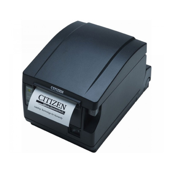
Citizen CT-S651 Series Service Manual
Compact line thermal printer
Hide thumbs
Also See for CT-S651 Series:
- User manual (46 pages) ,
- Command reference manual (454 pages) ,
- Programming manual (114 pages)

Related Manuals for Citizen CT-S651 Series


Summary of Contents for Citizen CT-S651 Series
-
Page 1: Service Manual
Service Manual COMPACT LINE THERMAL PRINTER CT-S651 Series Revision 1.00 2010.3.29... - Page 3 CT-S651 Series Service Manual REVISIONS Rev No. Date Page Comment 1.00 2010/3/29 Newly issued CITIZEN is a registered trademark of CITIZEN HOLDINGS CO., LTD., Japan. CITIZEN es una marca registrada de Citizen Holdings Co., Japón. - 1 -...
-
Page 4: Table Of Contents
CT-S651 Series Service Manual CONTENTS INTRODUCTION .....................4 DISASSEMBLY AND REASSEMBLY............4 1-1. Tools Used .........................4 1-2. Disassembly Procedure .....................5 1-2-1. Disassembling the Printer..................5 1-2-2. Disassembling “UNIT, MECHANISM” ..............14 1-3. Assembly Procedure......................23 1-4. Oiling..........................24 TROUBLESHOOTING ................27 2-1. Error Indication.........................27 2-2. Explanations of Error Conditions..................29 2-2-1. - Page 5 CT-S651 Series Service Manual 3-2-3. SA, SERIAL I/F PCB..................50 3-2-4. SA, PARALLEL I/F PCB..................51 3-2-5. SA, USB I/F PCB ....................51 3-2-6. SA, USB HUB I/F PCB ..................52 3-2-7. SA, POWERED USB I/F PCB ................52 3-2-8. SA, ETHERNET E Type I/F PCB ...............53 CIRCUIT DIAGRAMS................54...
-
Page 6: Introduction
CT-S651 Series Service Manual INTRODUCTION This manual describes the disassembly, reassembly, and maintenance procedures of CT-S651 Series. DISASSEMBLY AND REASSEMBLY Note the following items when performing maintenance of the printer. • Do not disassemble, reassemble, or adjust the printer unnecessarily when the printer operation is satisfactory. -
Page 7: Disassembly Procedure
CT-S651 Series Service Manual 1-2. Disassembly Procedure 1-2-1. Disassembling the Printer Disassembling “UNIT, I/F PCB” Remove two “SCREW, BHT (ST), M3.0 × 6” that fasten “FRAME, BOTTOM” and “UNIT, I/F PCB”. SCREW, BHT (ST), M3.0 × 6 Disassembling “SA, COVER-02”... - Page 8 CT-S651 Series Service Manual Since “SA, COVER-02” is secured with hooks and the boss, it cannot be removed easily when it is fully opened. To remove “SA, COVER-02”, slightly close it by hand, raise its front edge, and slide it backward.
- Page 9 CT-S651 Series Service Manual Disassembling “SA, HEAD COVER” Detach the lugs from the notches at the right and left sides of “COVER, FRAME”, and move down “SA, HEAD COVER” and pull it out with care so as not to damage the lugs.
- Page 10 CT-S651 Series Service Manual Align the bosses with <Precaution at reassembly> “SPRING, HEAD-02”. “SA, THERMAL HEAD-02” is electrostatically sensitive. Avoid contacting the heating section. When reassembling, insert the U-slot into “SHAFT, HEAD ADJUST-2”, and let the bosses fit into “SPRING, HEAD-02”.
- Page 11 CT-S651 Series Service Manual Disassembling “SA, FRONT COVER-02” Remove two “SCREW, BHT (ST), M3.0 × 6” that fasten “SA, FRONT COVER-02” and “SA, MAIN FRAME” and disconnect “SA, OPEPANE CABLE F” from the connector. Remove “HOLDER, FRONT COVER-02” from “SA, FRONT COVER-02”.
- Page 12 CT-S651 Series Service Manual Close “SA, COVER FRAME” slightly, and raise “SA, CASE-02” while pulling the right and left edges of “SA, CASE-02” outwardly. When “SA, CASE-02” is raised slightly, release “SA, COVER FRAME” and raise “SA, CASE-02” further while pulling the right and left edges outwardly and keeping the lugs at the rear clear of “FRAME, BOTTOM”.
- Page 13 CT-S651 Series Service Manual Remove “SA, OPEPANE CABLE-F” and “SA, CUTTER CABLE”. J17: SA, CUTTER SA, CUTTER CABLE J3: SA, OPEPANE SA, OPEPANE CABLE-F Disassembling “COVER, ADAPTER” Remove four “SCREW, BHT (ST), M3.0 × Remove the AC adaptor cable from the power connector.
- Page 14 CT-S651 Series Service Manual 10. Disassembling “FRAME, BOTTOM” Remove four “SCREW, BHT (ST), M3.0 × 6” Detach the lower lugs and raise “FRAME, BOTTOM”. that fasten “FRAME, BOTTOM” and “SA, Slide “FRAME, BOTTOM” upward to detach upper lugs MAIN FRAME”.
- Page 15 CT-S651 Series Service Manual 11. Disassembling “UNIT, MAIN PCB” Remove four “SCREW, BHT (ST), M3.0 × 6” Remove one “SCREW, BHT (ST), M3.0 × 6” that that fasten “UNIT, MAIN PCB” and “SA, MAIN fastens “COVER, CABLE PROTECT-02” at the right FRAME”.
-
Page 16: Disassembling "Unit, Mechanism
CT-S651 Series Service Manual 1-2-2. Disassembling “UNIT, MECHANISM” Disassembling “SA, COVER OPEN SENOR - F” Remove two “SCREW, No. 0 PHT (BT#3), M1.7 × 7” that fasten “SA, MAIN FRAME” and “SA, COVER OPEN SENSOR” (2 pcs), as well as the tape that secures “CABLE”. - Page 17 CT-S651 Series Service Manual Disassembling “UNIT, PNE-02” Remove two “SCREW, PHT (#2), M3.0 × 8” that fasten “SA, MAIN FRAME” and “PLATE, PNE SENSOR-02”, and remove “SA, HEAD CABLE-F” from the hook. Remove “PLATE, PNE SENSOR-02”, and then remove “UNIT, PNE -02”.
- Page 18 CT-S651 Series Service Manual Raise the rear of “SA, PAPER HOLDER-02” while pulling “GEAR, COVER DAMPER” outwardly, and detach the bosses from the slot at “SA, MAIN FRAME”. GEAR, COVER DAMPER SA, PAPER HOLDER-02 When removing “SA, PAPER HOLDER-02”, pull it upward while keeping it clear of the bosses at “SA, MAIN FRAME”...
- Page 19 CT-S651 Series Service Manual Disassembling “SA, PE SENSOR” Remove two “SCREW, PHT (BT), M2.0 × 6” that fasten “SA, PAPER HOLDER-02” and “SA, PE SENSOR”. SCREW, PHT (BT), M2.0 × 4 SA, PE SENSOR Disassembling “SA, FRAME COVER UNIT-02” Remove “WASHER, PLATEN” that fastens the hinged section at “SA, FRAME MAIN” to “SA, FRAME, COVER”...
- Page 20 CT-S651 Series Service Manual Remove “WASHER, PLATEN” from the “COVER, CABLE-02” side, and remove “SA, FRAME COVER UNIT-02” from the hinged section at “SA, MAIN FRAME”. When removing “SA, FRAME COVER UNIT-02”, make sure that “SA, FRAME COVER UNIT-02” is opened and that no load is applied to “SPRING, COVEROPEN-02”.
- Page 21 CT-S651 Series Service Manual Remove “SA, HEAD CABLE-02” from “COVER, CABLE-02”. Check the position of the tube end. Short Long Short Long Insert long cables first Top of “COVER, CABLE-02” and short ones next. <Precaution at reassembly> When reassembling, insert long cables into the left side of “SA, HEAD CABLE-02” at first, and then short ones into the right side.
- Page 22 CT-S651 Series Service Manual 10. Disassembling “PLATE, FIX BLADE” Remove two “SCREW, PHT (ST, SW + PW), M3.0 × 6” that fasten “FRAME COVER UNIT-02”, “PLATE, FIXED BLADE” and “GUIDE, PAPER-02”. SCREW, PHT (ST, SW + PW), M3.0 × 6...
- Page 23 CT-S651 Series Service Manual Remove two “SCREW, BHT (BT), M2.6 × 6” that fasten “SA, FRAME COVER UNIT-02” and “GUIDE, HEAD HOLDER-02”. SCREW, BHT (BT), M2.6 × 6 12. Disassembling “UNIT, MOTOR” Remove “SCREW, PHT (ST), M3.0 × 6” that fastens “SA, MAIN FRAME” and “UNIT, MOTOR”.
- Page 24 CT-S651 Series Service Manual 14. Disassembling “LEVER R & L, CUTTER RELEASE-02” Detach “SPRING, LEVER CUTTER-02” from the hooks at “SA, FRAME MAIN” and “LEVER R, CUTTER RELEASE-02”. Turn “LEVER R, CUTTER RELEASE -02” toward you and remove it from the shaft at “SA, FRAME MAIN”.
-
Page 25: Assembly Procedure
CT-S651 Series Service Manual 17. Disassembling “LEVER, COVER OPEN-02” Press down “LEVER, COVER OPEN-02”, align it with the slot at “SA, MAIN FRAME”, and pull it out toward you. 18. Disassembling “LEVER, INTERLOCK SENSOR-02” Remove “SCREW, PH (PW), M2.0 × 8” that fastens “LEVER, INTERLOCK SENSOR-02” and “SA, MAIN FRAME”. -
Page 26: Oiling
CT-S651 Series Service Manual 1-4. Oiling Oil Used (Grease) • FLOIL G311S (Kanto Kasei) • Daphne Eponex Grease No. 2 (Idemitsu) Oiling Positions <FLOIL G311S> (1) Shaft at “COVER GEAR” (2) Shafts at “SHAFT, PAPER HOLDER” (4 positions) Apply oil to the “HOLDER PAPER” side. - Page 27 CT-S651 Series Service Manual (4) Rotating center holes, press-formed projections and hooks at “LEVER R & L, CUTTER RELEASE-02” and “SA, MAIN FRAME” Rotating center holes, press-formed projections and hooks at “LEVER R & L, COVER LOCK-02” and “SA, MAIN FRAME”...
- Page 28 CT-S651 Series Service Manual (5) Both ends of the shaft at “SA CUTTER UNIT” <Daphne Eponex Grease No. 2> Right/left cutting edges of the blade at “SA, CUTTER UNIT” Daphne Eponex Grease No. 2 - 26 -...
-
Page 29: Troubleshooting
CT-S651 Series Service Manual TROUBLESHOOTING 2-1. Error Indication When an error is detected, the three LEDs indicate the error status in the following patterns. LED on the panel POWER LED (green) Lit: Power supplied Blinking: Memory check error, hex-dump mode, memory switch setting mode... - Page 30 CT-S651 Series Service Manual *1: This is the indication that appears when the paper cover is opened during standby. *2: This is the indication that appears when the paper cover is opened during paper feed or printing. *3: A buzzer beeps when MSW5-1 (buzzer setting) is ON.
-
Page 31: Explanations Of Error Conditions
CT-S651 Series Service Manual 2-2. Explanations of Error Conditions 2-2-1. Paper Near End When the diameter of the roll paper becomes small (less than 23 to 31 mm in diameter), the paper near-end sensor activates and indicates that the roll paper is running short. This message warns that the remaining paper is short. -
Page 32: Low Voltage Error
CT-S651 Series Service Manual 2-2-9. Low Voltage Error If the power supplied to the printer drops to 16 V or below, operation will stop. In this case, shut down the printer immediately. 2-2-10. High Voltage Error If the power supplied to the printer becomes 27 V or above, operation will stop. In this case, shut down the printer immediately. -
Page 33: Troubleshooting Procedure
CT-S651 Series Service Manual 2-3. Troubleshooting Procedure When a fault occurs, confirm its phenomenon, locate the problem in accordance with “2.2 Troubleshooting Guide”, and troubleshoot it as described below. Find the fault phenomenon in this column. If there are multiple phenomena, take all the applicable Phenomenon items into consideration. - Page 34 CT-S651 Series Service Manual ● Printing Failure Phenomenon Cause Check Method Remedies No printing The control PCB is faulty. Replace “SA, MAIN PCB”. − The thermal head connector Check the contact or Re-insert the thermal head has a bad contact or connecting condition.
- Page 35 CT-S651 Series Service Manual ● Paper Feed Failure Phenomenon Cause Check Method Remedies Paper is not fed. The motor connector has a Check the connecting Connect the connector bad connection. condition of the connector. correctly. Paper feed is not straight.
- Page 36 CT-S651 Series Service Manual ● Operation Panel Display Failure Phenomenon Cause Check Method Remedies The operation panel LED The connector has a bad Check the connecting Connect the connector does not illuminate. connection or cable condition of the connector. correctly.
-
Page 37: Service Parts List
CT-S651 Series Service Manual SERVICE PARTS LIST Remarks: All the parts used in the product are contained in “SERVICE PARTS LIST” in this Service Manual. However, note that all of them are not available with customers. When placing an order for service parts, refer to the Parts Price List published separately. If you need the Parts Price List, consult the local distributor from whom you purchased this product. - Page 38 CT-S651 Series Service Manual Part No. Part Name Q’ty Remarks TZ24221-0 COVER, HEAD-02 TZ24226-0 SHAFT, DAMPER-02 TZ24223-0 HOLDER, DAMPER PAPER-02 TZ22202-0 DAMPER, PAPER TZ24228-0 SUPPORT, DAMPER SPRING-02 TZ23616-0 SPRING, DAMPER-02 SCREW, No. 0 PH (BT2.5 × 0.5) M1.7 × 4...
- Page 39 CT-S651 Series Service Manual Part No. Part Name Q’ty Remarks TZ24218-0 BASE, PE SENSOR-02 Not supplied TZ24205-0 LEVER, PE SENSOR Not supplied TZ23606-0 SPRING, PE SENSOR Not supplied TZ68703-0 SA,PE SENSOR Not supplied SCREW, BHT (PT) M2.0 × 6 E12820-060F Not supplied SCREW, BHT (PT) M2.0 ×...
- Page 40 CT-S651 Series Service Manual Part No. Part Name Q’ty Remarks TZ54113-0 SHEET, OPE-PANE FEED 2-02 TZ67722-0 SA, OPEPANE CABLE-651 TZ44222-0 HOLDER, FRONT COVER-02 SCREW, BHT (ST), M3.0 × 6 E14030-060F 130-1 TZ56221-0 CASE-02 White 130-2 TZ56222-0 (BK) CASE BK-02 Black SCREW, BHT (ST), M3.0 ×...
- Page 41 CT-S651 Series Service Manual Part No. Part Name Q’ty Remarks TZ66718-0 SA, USB HUB I/F PCB TZ54105-0 PLATE, USB I/F 2 SCREW, BHT (ST), M3.0 × 4 E14030-040F SCREW, BHT (ST), M3.0 × 6 E14030-060F TZ66805-0 UNIT, ETHERNET E type I/F PCB...
- Page 42 CT-S651 Series Service Manual List of Screws Used Part No. Part Name SCREW, BH, M3.0 × 4 E00530-040F SCREW, PH (PW), M2.0 × 8 E00620-080F SCREW, PHT (PT) M2.0 × 8 E10120-080F SCREW, PHT (ST) M3.0 × 6 E00130-060F SCREW, PHT (#2), M3.0 × 8 E10130-080F SCREW, BHT (ST), M2.0 ×...
-
Page 43: Mechanical Exploded Diagrams
CT-S651 Series Service Manual 3-1-1. Mechanical Exploded Diagrams Exploded diagram 1 117-1 130-1 117-2 UNIT, COVER FRONT 130-2 (RART No. 118 - 126) 135-1 135-2 134-1 100-1 134-2 100-2 UNIT, MECHANISM (PART No. 2 - 115) 138-1 138-2 139-1 139-2... - Page 44 CT-S651 Series Service Manual Exploded diagram 2 118-1 118-2 For 2-inch model 101-2 101-1 For 3-inch model - 42 -...
- Page 45 CT-S651 Series Service Manual Exploded diagram 3 94-1 94-2 94-3 94-4 - 43 -...
- Page 46 CT-S651 Series Service Manual Exploded diagram 4 48-1 48-2 For 2-inch model For 3-inch model - 44 -...
- Page 47 CT-S651 Series Service Manual Exploded diagram 5 - 45 -...
- Page 48 CT-S651 Series Service Manual Exploded diagram 6 - 46 -...
- Page 49 CT-S651 Series Service Manual Exploded diagram 7 146, 151 144, 149 143, 148 145, 150 146, 151 142, 147 - 47 -...
-
Page 50: Parts Layout
CT-S651 Series Service Manual 3-2. Parts Layout 3-2-1. SA, MAIN PCB - 48 -... - Page 51 CT-S651 Series Service Manual - 49 -...
-
Page 52: Sa, Opepane Pcb-651
CT-S651 Series Service Manual 3-2-2. SA, OPEPANE PCB-651 3-2-3. SA, SERIAL I/F PCB - 50 -... -
Page 53: Sa, Parallel I/F Pcb
CT-S651 Series Service Manual 3-2-4. SA, PARALLEL I/F PCB 3-2-5. SA, USB I/F PCB - 51 -... -
Page 54: Sa, Usb Hub I/F Pcb
CT-S651 Series Service Manual 3-2-6. SA, USB HUB I/F PCB 3-2-7. SA, POWERED USB I/F PCB - 52 -... -
Page 55: Sa, Ethernet E Type I/F Pcb
CT-S651 Series Service Manual 3-2-8. SA, ETHERNET E Type I/F PCB - 53 -... -
Page 56: Circuit Diagrams
CT-S651 Series Service Manual CIRCUIT DIAGRAMS 4-1. MAIN PCB 4-1-1. Main Control Board (CPU1) - 54 -... -
Page 57: Main Control Board (Cpu2/Dac)
CT-S651 Series Service Manual 4-1-2. Main Control Board (CPU2/DAC) - 55 -... -
Page 58: Main Control Board (Rom)
CT-S651 Series Service Manual 4-1-3. Main Control Board (ROM) - 56 -... -
Page 59: Main Control Board (Ram)
CT-S651 Series Service Manual 4-1-4. Main Control Board (RAM) - 57 -... -
Page 60: Main Control Board (Gate_Array)
CT-S651 Series Service Manual 4-1-5. Main Control Board (GATE_ARRAY) - 58 -... -
Page 61: Main Control Board (Head, Op-Panel)
CT-S651 Series Service Manual 4-1-6. Main Control Board (HEAD, OP-PANEL) - 59 -... -
Page 62: Main Control Board (Pf Motor)
CT-S651 Series Service Manual 4-1-7. Main Control Board (PF MOTOR) - 60 -... -
Page 63: Main Control Board (Sensor)
CT-S651 Series Service Manual 4-1-8. Main Control Board (SENSOR) - 61 -... -
Page 64: Main Control Board (Power/Drawer/Buzzer)
CT-S651 Series Service Manual 4-1-9. Main Control Board (POWER/DRAWER/BUZZER) - 62 -... -
Page 65: Main Control Board (If Pcb Con / Option If)
CT-S651 Series Service Manual 4-1-10. Main Control Board (IF PCB CON / OPTION IF) - 63 -... -
Page 66: Main Control Board (Cutter)
CT-S651 Series Service Manual 4-1-11. Main Control Board (CUTTER) - 64 -... -
Page 67: Pe, Pne Sensor
CT-S651 Series Service Manual 4-2. PE, PNE Sensor 4-3. Operation Panel - 65 -... -
Page 68: Serial I/F Pcb
CT-S651 Series Service Manual 4-4. Serial I/F PCB - 66 -... -
Page 69: Parallel I/F Pcb
CT-S651 Series Service Manual 4-5. Parallel I/F PCB - 67 -... -
Page 70: Usb I/F Pcb
CT-S651 Series Service Manual 4-6. USB I/F PCB - 68 -... -
Page 71: Usb Hub I/F Pcb
CT-S651 Series Service Manual 4-7. USB HUB I/F PCB - 69 -... -
Page 72: Powered Usb I/F Pcb
CT-S651 Series Service Manual 4-8. POWERED USB I/F PCB - 70 -... -
Page 73: Ethernet E Type I/F Pcb
CT-S651 Series Service Manual 4-9. ETHERNET E Type I/F PCB 4-9-1. CPU1 - 71 -... -
Page 74: Cpu2
CT-S651 Series Service Manual 4-9-2. CPU2 4-9-3. SD RAM - 72 -... -
Page 75: Phy
CT-S651 Series Service Manual 4-9-4. PHY - 73 -... -
Page 76: I/F
CT-S651 Series Service Manual 4-9-5. I/F - 74 -...