Cisco ASR 903 Installation Manual
Aggregation services router hardware
Hide thumbs
Also See for ASR 903:
- Release notes (280 pages) ,
- Hardware installation manual (196 pages) ,
- Manual (147 pages)
Table of Contents
Advertisement
Quick Links
Cisco ASR 903 and ASR 903U Aggregation Services Router Hardware
Installation Guide
First Published: 2015-10-01
Last Modified: 2018-02-20
Americas Headquarters
Cisco Systems, Inc.
170 West Tasman Drive
San Jose, CA 95134-1706
USA
http://www.cisco.com
Tel: 408 526-4000
800 553-NETS (6387)
Fax: 408 527-0883
Advertisement
Table of Contents

Related Manuals for Cisco ASR 903


Summary of Contents for Cisco ASR 903
-
Page 1: Installation Guide
Cisco ASR 903 and ASR 903U Aggregation Services Router Hardware Installation Guide First Published: 2015-10-01 Last Modified: 2018-02-20 Americas Headquarters Cisco Systems, Inc. 170 West Tasman Drive San Jose, CA 95134-1706 http://www.cisco.com Tel: 408 526-4000 800 553-NETS (6387) Fax: 408 527-0883... - Page 2 © 2015 - 2018 Cisco Systems, Inc. All rights reserved.
-
Page 3: Table Of Contents
A900-RSP3C-200-S Supported Interface Modules Supported RSP Features RSP Redundancy Network Timing Interfaces RSP Interfaces GNSS Module (A900-CM-GNSS) GNSS Module RF Input Requirements Interface Modules 8-Port 1 Gigabit Ethernet SFP Interface Module Cisco ASR 903 and ASR 903U Aggregation Services Router Hardware Installation Guide... - Page 4 Temperature Sensor Temperature Sensors on the A900 RSP1 and A900 RSP2 modules Temperature Sensors on the A900 RSP3 modules Serial Number Label Location Patch Panels Interface Numbering Regulatory Compliance Cisco ASR 903 and ASR 903U Aggregation Services Router Hardware Installation Guide...
- Page 5 Rack Selection Guidelines Equipment Rack Guidelines Installation Checklist Creating a Site Log Receiving the Cisco ASR 903 Router Chassis-Lifting Guidelines Tools and Equipment Unpacking and Verifying the Shipped Contents Cisco ASR 903 and ASR 903U Aggregation Services Router Hardware Installation Guide...
- Page 6 Installing the DC Power Supply Module Connecting DC Power Supply Unit (A900-PWR900-D2) Activating the DC Power Supply Removing and Replacing the DC Power Supply Installing the AC power Supply Cisco ASR 903 and ASR 903U Aggregation Services Router Hardware Installation Guide...
- Page 7 Patch Panel Cabling for Redundancy RJ45 Cable Pinouts Connecting Cables to the Patch Panel Patch Panel Connectors Recommended Patch Panel Installing Patch Panel Installing the 3G Patch Panel Cisco ASR 903 and ASR 903U Aggregation Services Router Hardware Installation Guide...
- Page 8 32 T1/E1 Interface Module Pinout 8 T1/E1 Interface Module RJ48C Port Pinnouts T1/E1 Port Pinout RJ48 T1/E1 Port Pinouts Serial Cable Pinouts DB-9 Connector Pinouts RJ-45 Connector Pinouts Cisco ASR 903 and ASR 903U Aggregation Services Router Hardware Installation Guide viii...
- Page 9 E and M Interface Module LEDs 4-Port C37.94 Interface Module LEDs Power Supply LEDs Fan Tray LEDs Alarm Conditions A P P E N D I X A Site Log and Manufactures Manufactures Cisco ASR 903 and ASR 903U Aggregation Services Router Hardware Installation Guide...
- Page 10 Contents Cisco ASR 903 and ASR 903U Aggregation Services Router Hardware Installation Guide...
-
Page 11: Cisco Asr 903 Router Features
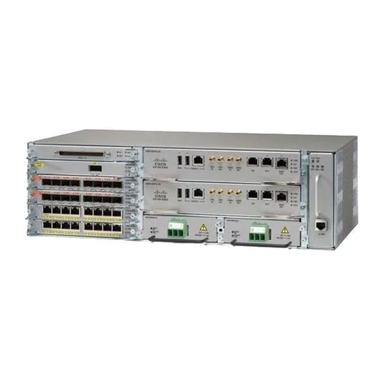
Overview Note The Cisco ASR 903 Router and the Cisco ASR 903U Router are collectively referred to as the Cisco ASR 903 Router in this document. Any differences between the routers are specifically called out. The Cisco ASR 903 Router is a fully-featured aggregation platform designed for the cost-effective delivery of converged mobile and business services. -
Page 12: Power Supply Features
Redundant power units (two DC power units are shown) Power Supply Features The Cisco ASR 903 Router support AC and DC power supplies. For more information about installing the Cisco ASR 903 Router power supplies, see the Installing the Power Supply. -
Page 13: Dying Gasp
Overview Dying Gasp supplies or a combination of AC and DC power supply. The Cisco ASR 903 Router supports current sharing between the power supplies. A redundant power supply on the Cisco ASR 903 Router is recommended. Each power supply should be connected to separate independent power sources to ensure that the router maintains power in the event of a power interruption caused by an electrical failure, a wiring fault, or a tripped circuit breaker. - Page 14 DC Power Specifications 550 W, we recommend using the A900-PWR1200-D power supply with A900-RSP3C-400-S RSP modules. Figure 2: DC PSU Module (A900-PWR550-D) with Euro-style Connector Euro-style connector — Cisco ASR 903 and ASR 903U Aggregation Services Router Hardware Installation Guide...
- Page 15 Table 1: DC Power Supply Specifications (550 W) Part numbers A900-PWR550-D, A900-PWR550-D-E Input power specification +24V/-48V or -60V VDC Minimum input voltage 19.2 VDC Maximum input voltage 72 VDC Output voltage +12 VDC Cisco ASR 903 and ASR 903U Aggregation Services Router Hardware Installation Guide...
- Page 16 550 W Figure 4: DC PSU Module (A900-PWR1200-D) Label Component T-shaped connector Table 2: DC Power Supply Specifications (A900-PWR1200-D) Part numbers A900-PWR1200-D Input power specification 48V, GRD, -48V Cisco ASR 903 and ASR 903U Aggregation Services Router Hardware Installation Guide...
-
Page 17: Ac Power Specifications
Table 3: AC Power Supply Specifications (A900-PWR550-A) Part number A900-PWR550-A Input power specification 115VAC/ 230VAC Input voltage 85/264 VAC Minimum input voltage 85 VAC Maximum input voltage 264 VAC Minimum output voltage Cisco ASR 903 and ASR 903U Aggregation Services Router Hardware Installation Guide... -
Page 18: Fan Tray
85 VAC Maximum input voltage 264 VAC Minimum output voltage Maximum output voltage 12.4V Maximum power output 1200 W Fan Tray The fan tray has the following hardware features: Cisco ASR 903 and ASR 903U Aggregation Services Router Hardware Installation Guide... -
Page 19: Fan Tray (A903-Fan)
ASR 903 router. Fan Tray (A903-FAN) The Cisco ASR 903 Router uses a modular fan tray that is separate from the power supply. The fan tray contains twelve fans and provides sufficient capacity to maintain operation indefinitely in the event of an individual fan failure. -
Page 20: Fan Tray (A903-Fan-E)
It has a 8 mm fan dust filter that prevents dust from entering the unit and avoids possible damage to the components. The fan tray is IEC60950-1 compliant. Cisco ASR 903 and ASR 903U Aggregation Services Router Hardware Installation Guide... -
Page 21: Air Plenum
Overview Dust Filter (A903-FAN-F) Figure 7: Cisco ASR 903 Fan Tray with Dust Filter and Dummy Cover (A903-FAN-E) LEDs Dummy cover Alarm Pull tab Dust filter — Dust Filter (A903-FAN-F) The dust filter on the fan tray is a quadrafoam 45PPI filter which is 85 percent dust resistant. A dummy cover (A903-FAN-F-B) secures the dust filter in the chassis. -
Page 22: Rsp Modules
RSP Modules The Cisco ASR 903 Router is designed to use up to two RSP modules to handle the data plane, network timing, and control plane functionalities for the router. The RSP configuration allows you to use Cisco IOS software to control chassis management, redundancy, external management, and system status indications on the router. - Page 23 Figure 8: A900-RSP1 Module Figure 9: A900-RSP2A-128 Module SD memory card SD memory card slot Note Installing a mix of RSP modules in the chassis is not supported. Cisco ASR 903 and ASR 903U Aggregation Services Router Hardware Installation Guide...
-
Page 24: A900-Rsp1 Supported Interface Modules
The RSPs do not provide external network interfaces for user traffic. All network interfaces are provided via separate IMs. Figure 10: A900-RSP3C-400-S RSP Module Figure 11: A900-RSP3C-200-S RSP Module A900-RSP1 Supported Interface Modules The table below is applicable for A900-RSP1A-55 and A900-RSP1B-55 RSP modules. Cisco ASR 903 and ASR 903U Aggregation Services Router Hardware Installation Guide... -
Page 25: A900-Rsp2 Supported Interface Modules
Note The combination interface modules (A900-IMA8S1Z, A900-IMA8T1Z), and the A900-IMA2Z interface module are not supported on the A900-RSP1A-55 and A900-RSP1B-55 modules on the Cisco ASR 903 Router. A900-IMA2Z IM supports SFP+ and XFP on ports 0 and 1. Either SFP+ or XFP can be connected on each port. - Page 26 Table 7: A900-RSP2A-64 Supported Interface Modules and Part Numbers Supported Interface Modules Part Numbers Slot 1-port 10 Gigabit Ethernet XFP Interface Module (1x10GE) A900-IMA1X 2-port 10 Gigabit Ethernet Interface Module (2x10GE) A900-IMA2Z Cisco ASR 903 and ASR 903U Aggregation Services Router Hardware Installation Guide...
-
Page 27: A900-Rsp3C-400-S Supported Interface Modules
The table below is applicable for A900-RSP3C-400-S RSP module. Note There are certain restrictions in using the interface modules on different slots with RSP3 module. Contact Cisco Sales/Support for the valid combinations. Cisco ASR 903 and ASR 903U Aggregation Services Router Hardware Installation Guide... -
Page 28: A900-Rsp3C-200-S Supported Interface Modules
8-port Low Rate Interface Module 48-port T1/E1 CEM Interface A900-IMA48D-C Module 48-port T3/E3 CEM Interface A900-IMA48T-C Module A900-RSP3C-200-S Supported Interface Modules The table below is applicable for A900-RSP3C-200-S RSP module. Cisco ASR 903 and ASR 903U Aggregation Services Router Hardware Installation Guide... -
Page 29: Supported Rsp Features
RSP Redundancy The Cisco ASR 903 Router chassis includes two RSP slots to allow for redundant RSPs. When the router uses redundant RSPs, one RSP operates in the active mode and the other operates in the hot standby mode. Removal or failure of the active RSP results in an automatic switchover to the standby RSP. -
Page 30: Network Timing Interfaces
10 MHz input timing port 10 MHz output timing port Time of Day (ToD) timing port BITS timing port Ethernet management port Figure 13: Cisco A900-RSP2A Interface Summary Cisco ASR 903 and ASR 903U Aggregation Services Router Hardware Installation Guide... - Page 31 Time of Day (ToD) timing port BITS timing port Ethernet management port The Cisco A900-RSP2A module has the following front panel interfaces. For information on cable pinout, see Troubleshooting. • 1 USB Type-A Connector for USB-flash (Label = “MEM”) • 1 USB Type-A Connector for alternate console port (Label = “CONSOLE”) •...
-
Page 32: Gnss Module (A900-Cm-Gnss)
RSP LEDs, see LEDs. GNSS Module (A900-CM-GNSS) The GNSS module is present on the RSP3 modules. It is a pluggable module that allows direct interface with the external antenna. Cisco ASR 903 and ASR 903U Aggregation Services Router Hardware Installation Guide... -
Page 33: Gnss Module Rf Input Requirements
National Electrical Code (NEC), in particular Section 820.93, Grounding of Outer Conductive Shield of a Coaxial Cable. • Use a passive splitter if more than one GNSS modules are fed from a single antenna. For information on pinout, see GPS Port Pinout. Cisco ASR 903 and ASR 903U Aggregation Services Router Hardware Installation Guide... -
Page 34: 8-Port 1Gigabit Ethernet Rj45 Interface Module
Overview Interface Modules Interface Modules The Cisco ASR 903 Router interface modules are a field-replaceable units. In addition to the ports provided on an RSP, the Cisco ASR 903 Router supports the following interface modules: Note For information about supported interface modules, see the Release Notes for the Cisco ASR 903 Series Aggregation Services Router. -
Page 35: 1-Port 10 Gigabit Ethernet Xfp Interface Module
For information on supported SFP modules, see Cisco ASR 900 Series Aggregation Services Routers Data Sheet. For more information about installing a 1-port 10 GE XFP module, see the Interface Module Installation Cisco ASR 903 and ASR 903U Aggregation Services Router Hardware Installation Guide... -
Page 36: 8-Port 10 Gigabit Ethernet Interface Module (8X10Ge)
The 8-port 1 Gigabit Ethernet SFP interface module with the 1-port 10 Gigabit Ethernet interface module is a high density combination interface module. This module supports 8 Gigabit Ethernet SFP ports and 1 10 Gigabit Ethernet SFP+ port. Cisco ASR 903 and ASR 903U Aggregation Services Router Hardware Installation Guide... -
Page 37: 8-Port 1 Gigabit Ethernet + 1-Port 10 Gigabit Ethernet Sfp+ Combination Interface Module
This 8-port 1 Gigabit Ethernet (RJ45 Copper) interface module with the 1-port 10 Gigabit Ethernet interface module is a high density combination interface module. This module supports 8 Gigabit Ethernet Copper ports and 1 10 Gigabit Ethernet SFP+ port. Cisco ASR 903 and ASR 903U Aggregation Services Router Hardware Installation Guide... -
Page 38: 2-Port 10 Gigabit Ethernet Sfp+ Interface Module
For information on supported SFP modules, see Cisco ASR 900 Series Aggregation Services Routers Data Sheet. For more information about installing the 2-port 10 GE SFP Gigabit Ethernet module, see Interface Module Installation. Cisco ASR 903 and ASR 903U Aggregation Services Router Hardware Installation Guide... -
Page 39: 1-Port 100 Gigabit Ethernet Interface Module (1X100Ge)
The dual port 40 Gigabit Ethernet interface module supports the 40 Gigabit Ethernet port. The 40GE interface is supported using QSFP+ optics. The figure below shows the interface module. Figure 24: 2-port 40 Gigabit Ethernet Interface Module Cisco ASR 903 and ASR 903U Aggregation Services Router Hardware Installation Guide... -
Page 40: Ethernet (Csfp) Interface Module
• 16 x 1GigE (C-SFP) + 1 x 10GigE (SFP+) Oversubscribed mode (OS) • 8 or 9 x 1GigE (SFP) Fully subscribed mode (FS) • 1 x 10GigE (SFP+) Fully subscribed mode (FS) Cisco ASR 903 and ASR 903U Aggregation Services Router Hardware Installation Guide... -
Page 41: 16-Port T1/E1 Interface Module
Gigabit Ethernet (1 X SFP) / 2-port Gigabit Ethernet (1 X CSFP) and 16-port Gigabit Ethernet (8 X CSFP) / 8-port Gigabit Ethernet (8 X SFP) Interface Module chapter of the Cisco ASR 900 Router Series Configuration Guide, Cisco IOS XE Everest 16.6.1. -
Page 42: 8-Port T1/E1 Interface Module
The figure below shows the interface module. For information on supported slots, see Supported RSPs. Figure 28: 8-portT1/E1 Interface Module For more information about installing a 8-port T1/E1 interface module, see the Interface Module Installation. Cisco ASR 903 and ASR 903U Aggregation Services Router Hardware Installation Guide... -
Page 43: 48-Port T1/E1 Cem Interface Module
The 48-port T3/E3 interface module provides connectivity for up to 48 T3/E3 ports through 3 high-density connectors on the front panel (see the figure below ). Each port supports 16 TX and RX ports. For information on LEDs, see Interface Module LEDs. Cisco ASR 903 and ASR 903U Aggregation Services Router Hardware Installation Guide... -
Page 44: 4-Port Oc3/Stm-1 (Oc-3) Or 1-Port Oc12/Stm-4 (Oc-12) Interface Module
STM-1 interfaces. The figure below shows the interface module. Note The optical interface module is designed for OC-3 and OC-12 traffic. OC-12 is only supported on the RSP1 module on the router. Cisco ASR 903 and ASR 903U Aggregation Services Router Hardware Installation Guide... -
Page 45: Cem Interface Module
• 12xDS1/E1 + 4xDS3/E3 interface over the high-density port. • 1xOC48/12/3 Gigabit interface and 3xOC12/3 Gigabit interface. Note If OC48 is enabled, then the remaining 3 ports are disabled. Cisco ASR 903 and ASR 903U Aggregation Services Router Hardware Installation Guide... -
Page 46: 1-Port Oc-192 Or 8-Port Low Rate Cem Interface Module (10G Ho / 10G Lo)
This module supports 1 OC-192 port or 8 low rate CEM or 1 Gigabit Ethernet port. Figure 35: OC-192 Interface Module Figure 36: OC-192 Interface Module Faceplate The OC-192 interface modules are supported on slots 2, 3, 4 and 5 on the chassis. Cisco ASR 903 and ASR 903U Aggregation Services Router Hardware Installation Guide... - Page 47 For information on supported SFP modules, see Cisco ASR 900 Series Aggregation Services Routers Data Sheet. For more information about installing an optical interface module, see Interface Module Installation. Cisco ASR 903 and ASR 903U Aggregation Services Router Hardware Installation Guide...
-
Page 48: 14-Port Serial Interface Module
14-Port Serial Interface Module 14-Port Serial Interface Module The Cisco (A900-IMASER14A/S) is a 14-port serial interface module for the Cisco ASR 903 router. The Cisco ASR 903 Router module has the following interfaces: • 12-in-1 Connector (6)-Supports synchronous and asynchronous RS-232 interfaces using EIA/TIA-232 DB-25 connectors •... -
Page 49: 6-Port E And M Interface Module
Cables. 6-Port E and M Interface Module The Cisco (A900-IMA6EM) is a 6-port Ear and Mouth (E&M) interface module for the Cisco ASR 903 router. The interface module provides the router with connectivity to tele-protection equipments. The front panel of the module consists of: •... -
Page 50: 4-Port C37.94 Interface Module
Caution The A900-IMA-BLNK-DEF is module should not be used in slot 0 in the Cisco ASR 903 Router. For slot 0, always use the filler blank (A900-IMA-BLANK) when a blank filler needs to be used. - Page 51 –40 to 65 1 A900-IMA8S A900-IMA2Z A900-IMA8T1Z A900-IMA8S1Z A900-IMA8Z A903-FAN –40 to 65 1 A900-IMA2F A903-FAN-E –40 to 55 Maximum operating temperature of 65°C is supported only with EXT/RGD/IND optical modules. Cisco ASR 903 and ASR 903U Aggregation Services Router Hardware Installation Guide...
-
Page 52: Temperature Sensor
A900-IMA8Z Temperature Sensor The Cisco ASR 903 Router has a temperature sensor to detect overtemperature conditions inside the chassis. Temperature Sensors on the A900 RSP1 and A900 RSP2 modules The overtemperature detection trips at 75 degrees C +/- 5% with the ambient (inlet) trip point at 67 degrees C. -
Page 53: Patch Panels
Figure 42: Cisco ASR 903 Router Serial Number Location Patch Panels The Cisco NCS 4206 has patch panels modules that provide interconnections with the interface modules. The following table shows different types of patch panel: Table 12: T1/E1 Patch Panel... -
Page 54: Interface Numbering
Figure 44: Patch Panel DSX Interface View Figure 45: Patch Panel System Interface View Interface Numbering The Cisco ASR 903 Router chassis includes: • Six interface module slots Cisco ASR 903 and ASR 903U Aggregation Services Router Hardware Installation Guide... - Page 55 • Two power supply slots • One fan tray slot Each network interface on a Cisco ASR 903 Router is identified by a slot number and a port number. The figure below shows interface numbering in a Cisco ASR 903 Router.
-
Page 56: Regulatory Compliance
• set platform software trace iomd Regulatory Compliance For regulatory compliance and safety information, see the Product Documentation and Compliance for the Cisco ASR 900 Series Aggregation Services Routers document. Cisco ASR 903 and ASR 903U Aggregation Services Router Hardware Installation Guide... -
Page 57: Preparing For Installation
C H A P T E R Preparing for Installation This chapter describes how to prepare for the installation of the Cisco ASR 903 Router at your site. • Safety Guidelines, on page 47 • Site Planning, on page 57 •... - Page 58 Statement 1035 Warning Never install telephone jacks in wet locations unless the jack is specifically designed for wet locations. Statement 1036 Cisco ASR 903 and ASR 903U Aggregation Services Router Hardware Installation Guide...
- Page 59 This is a Class A Device and is registered for EMC requirements for industrial use. The seller or buyer should be aware of this. If this type was sold or purchased by mistake, it should be replaced with a residential-use type. Statement 294 Cisco ASR 903 and ASR 903U Aggregation Services Router Hardware Installation Guide...
-
Page 60: Safety Guidelines For Personal Safety And Equipment Protection
Warning Class 1M laser radiation when open. Do not view directly with optical instruments. Statement 1053 Warning Class 1 (CDRH) and Class 1M (IEC) laser products. Statement 1055 Cisco ASR 903 and ASR 903U Aggregation Services Router Hardware Installation Guide... -
Page 61: Safety With Electricity
Metal objects will heat up when connected to power and ground and can cause serious burns or weld the metal object to the terminals. Statement 43 Cisco ASR 903 and ASR 903U Aggregation Services Router Hardware Installation Guide... - Page 62 10 AWG minimum with a 50 A circuit breaker. Statement 1005 Warning This product relies on the building’s installation for short-circuit (overcurrent) protection. For an AC installation, ensure that the branch circuit breaker is rated a maximum 20A. Cisco ASR 903 and ASR 903U Aggregation Services Router Hardware Installation Guide...
- Page 63 Hazardous network voltages are present in WAN ports regardless of whether power to the unit is OFF or ON. To avoid c shock, use caution when working near WAN ports. When detaching cables, detach the end away from the unit first. Statement 1026 Cisco ASR 903 and ASR 903U Aggregation Services Router Hardware Installation Guide...
- Page 64 Install only in accordance with national and local wiring regulations. Statement 1045 Warning When installing or replacing the unit, the ground connection must always be made first and disconnected last. Statement 1046 Cisco ASR 903 and ASR 903U Aggregation Services Router Hardware Installation Guide...
- Page 65 • Never assume that power is disconnected from a circuit; always check. • Never perform any action that creates a potential hazard to people or makes the equipment unsafe. Cisco ASR 903 and ASR 903U Aggregation Services Router Hardware Installation Guide...
-
Page 66: Power Supply Considerations
• When removing a component, use available ejector levers or captive installation screws, if any, to release the bus connectors from the backplane or midplane. • Handle components by their handles or edges only; do not touch the printed circuit boards or connectors. Cisco ASR 903 and ASR 903U Aggregation Services Router Hardware Installation Guide... -
Page 67: Site Planning
• The site meets the environmental requirements. • The site’s air conditioning system can compensate for the heat dissipation of the Cisco ASR 903 Router. • The floor space that the Cisco ASR 903 Router occupies can support the weight of the system. -
Page 68: Site Selection Guidelines
Sheet. Air Flow Guidelines Cool air is circulated through the Cisco ASR 903 Router by a fan tray located along the right side of the router. Air flow is side-to-side, right to left, as shown in the figure below . -
Page 69: Air Flow Guidelines For Enclosed Rack Installation
Air Flow Guidelines for Enclosed Rack Installation To install a Cisco ASR 903 Router in a 4-post enclosed cabinet, the front and rear doors of the cabinet must be removed or be perforated with a minimum of 65% open area (70% for ETSI 800mm racks). -
Page 70: Floor Loading Considerations
(15.24 cm) of clearance on each side of the chassis. Floor Loading Considerations Ensure that the floor under the rack supporting the Cisco ASR 903 Routers is capable of supporting the combined weight of the rack and all the other installed equipment. - Page 71 A900-IMA8S1Z (8-port 1GE SFP + 1-port 10 GE Interface Module) 29 W A900-IMA8T1Z (8-port 1GE RJ-45 Copper + 1 10 GE Interface Module 27 W A900-IMA2Z (2-port 10 GE Interface Module) 24 W Cisco ASR 903 and ASR 903U Aggregation Services Router Hardware Installation Guide...
-
Page 72: Electrical Circuit Requirements
The Cisco ASR 903 Routers can be powered by a DC source or an AC source. Ensure that equipment grounding is present and observe the power strip ratings. Make sure that the total ampere rating of all products plugged into the power strip does not exceed 80% of the rating. -
Page 73: Asynchronous Terminal Connections
The typical sources of EMI are equipment power cords and power service cables from electric utility companies. Strong EMI can destroy the signal drivers and receivers in the Cisco ASR 903 Router and even create an electrical hazard by causing power surges through the power lines into installed equipment. These problems are rare but could be catastrophic. -
Page 74: Rack-Mounting Guidelines
• Do not step on or stand on any component or system when servicing other systems or components in a rack. • When mounting the Cisco ASR 903 Router in a partially filled rack, load the rack from the bottom to the top, with the heaviest component at the bottom of the rack. -
Page 75: Equipment Rack Guidelines
Locating for Safety If the Cisco ASR 903 Router is the heaviest or the only piece of equipment in the rack, consider installing it at or near the bottom to ensure that the rack’s center of gravity is as low as possible. -
Page 76: Installation Checklist
To assist you with your installation and to provide a record of what was done by whom and when, photocopy the Cisco ASR 903 Router Installation Checklist shown in the table below. Use this to record the completion and verification of each procedure. After the checklist is completed, place it in your Site Log along with the other records pertaining to your new Cisco router. -
Page 77: Receiving The Cisco Asr 903 Router
Log as well as a sample Site Log that can be used to make copies. Receiving the Cisco ASR 903 Router Each Cisco ASR 903 Router chassis is shipped in a container. See the figure below . Figure 48: Cisco ASR 903 Router Packaged for Shipping... -
Page 78: Tools And Equipment
• Always disconnect all external cables before lifting or moving the chassis. • Do not carry the chassis in any other packaging except as provided by Cisco packaging. Usage of other inferior packaging for equipment movement may cause severe damage to the product. -
Page 79: Unpacking And Verifying The Shipped Contents
Step 4 Use the table below to check the contents of the Cisco ASR 903 Router shipping container. Do not discard the shipping container. You will need the container if you move or ship the Cisco ASR 903 Router in the future. - Page 80 • T1/E1 cable connector (required only for T1/E1 interface modules) Note Most Cisco documentation is available online. Documentation that is shipped with your Cisco ASR 903 Router includes the Regulatory Compliance and Safety Information for the Cisco ASR 903 Router document, and the Cisco ASR 903 Router Documentation Roadmap that contains information about the various documents that are available online and the links to them.
-
Page 81: Installing The Cisco Asr 903 Router
• Unpacking and inspecting the Cisco ASR 903 Router • Gathering the tools and test equipment required to properly install the Cisco ASR 903 Router For more instructions on how to prepare for the installation of the Cisco ASR 903 Router, see Preparing for... -
Page 82: Installing The Router Chassis In The Rack
Figure 49: Attaching Mounting Brackets for a 19-inch EIA Rack The figure below shows how to attach the brackets on the Cisco ASR 903 Router for a 300 mm ETSI cabinet. Figure 50: Attaching Mounting Brackets for a 300 mm ETSI Cabinet Step 2 Position one of the brackets against the chassis side, and align the screw holes. - Page 83 Figure 51: Installing the Chassis in a 19-inch EIA Rack Figure 52: Installing the Chassis to support the Japanese JIS Rack Standard Cisco ASR 903 and ASR 903U Aggregation Services Router Hardware Installation Guide...
- Page 84 Installing the Cisco ASR 903 Router Installing the Router Chassis in the Rack Figure 53: Installing the Chassis in a 300 mm ETSI Cabinet Figure 54: Vertical Mounting Installation Cisco ASR 903 and ASR 903U Aggregation Services Router Hardware Installation Guide...
-
Page 85: Installing Plenum A903-F2B-Air-U Assembly And Chassis In The Rack
Position the air baffle and the side plate to the plenum. Secure the air baffle and the side plate using a maximum torque of 11.5 in.-lb (1.3 N-m). See figure below. Cisco ASR 903 and ASR 903U Aggregation Services Router Hardware Installation Guide... - Page 86 Air baffle Plenum base Side plate Secure screw to Plenum base Step 2 Secure the air baffle using a maximum torque of 11.5 in.-lb (1.3 N-m). See figure below. Cisco ASR 903 and ASR 903U Aggregation Services Router Hardware Installation Guide...
- Page 87 Step 4 Position the air filter (A903-F2B-AIR-F) assembly on the plenum deflector. Secure the front cover using a recommended torque of 11.5 in.-lb (1.3 N-m). See figure below. Cisco ASR 903 and ASR 903U Aggregation Services Router Hardware Installation Guide...
- Page 88 Using a crimping tool (as specified by the ground lug manufacturer), crimp the ground lug to the ground wire and connect the other end of the ground wire to a suitable grounding point at your site. See figure below. Cisco ASR 903 and ASR 903U Aggregation Services Router Hardware Installation Guide...
- Page 89 Position the plenum assembly to the rack and secure the cable brackets to the rack using a torque of 11.5 in.-lb (1.3 N-m). See figure below. For a 19-inch rack installation, the rack has to have a flat post. Note Cisco ASR 903 and ASR 903U Aggregation Services Router Hardware Installation Guide...
- Page 90 Installing the Cisco ASR 903 Router Installing Plenum A903-F2B-AIR-U Assembly and Chassis in the Rack Figure 60: Plenum Assembly to 21-inch Rack Cisco ASR 903 and ASR 903U Aggregation Services Router Hardware Installation Guide...
- Page 91 Installing the Cisco ASR 903 Router Installing Plenum A903-F2B-AIR-U Assembly and Chassis in the Rack Figure 61: Plenum Assembly to 23-inch Rack Secure screws to rack — — Cisco ASR 903 and ASR 903U Aggregation Services Router Hardware Installation Guide...
-
Page 92: Installing The Chassis In The Air Plenum
To install the optional cable management brackets, perform these steps: Step 1 Position the cable management brackets against the front of the chassis and align the four screw holes, as shown in the figure below. Cisco ASR 903 and ASR 903U Aggregation Services Router Hardware Installation Guide... -
Page 93: Installing The Chassis Ground Connection
Secure the cable management brackets with four M4 screws. The recommended maximum torque is 10 in.-lb (1.12 N-m). Installing the Chassis Ground Connection Before you connect the power or turn on the power to the Cisco ASR 903 Router, you must provide an adequate chassis ground (earth) connection to your router. - Page 94 • Wire-stripping tools appropriate to the wire you are using Caution Before making connections to the Cisco ASR 903 Router, ensure that you disconnect the power at the circuit breaker. Otherwise, severe injury to you or damage to the router may occur.
- Page 95 This unit is to be installed in a restrictive access location and must be permanently grounded to minimum 6 AWG copper ground wire. Perform the following procedure to ground the Cisco ASR 903 Router using a 2-hole lug and the corresponding mounting point. Most carriers require a minimum 6 AWG ground connection. Verify your carrier’s requirements for the ground connection.
-
Page 96: Installing The Fan Tray
Installing the Cisco ASR 903 Router Installing the Fan Tray Installing the Fan Tray The fan tray is a modular unit that provides cooling to the Cisco ASR 903 Router. Follow these steps to install the fan tray in the chassis: Step 1 Orient the fan tray so that the captive screws are on the left side of the fan tray’s front panel. -
Page 97: Removing The Dust Filter
Removing and Replacing the Fan Tray The fan tray supports online insertion and removal (OIR). There is no need to power down the Cisco ASR 903 Router to remove or replace the fan tray. However, there is a finite time to replace the fan tray. This time depends upon the specific RSP and fan tray combination and also the ambient temperature. - Page 98 To avoid erroneous failure messages, allow at least 2 minutes for the system to reinitialize, after the fan tray has been removed or replaced. This is applicable when the RSP1 and RSP2 modules are installed in the chassis. Follow these steps to remove and replace the fan tray on the Cisco ASR 903 Router: Step 1 Using a No.
-
Page 99: Rsp Installation
To install the new fan tray, follow the steps inInstalling the Fan Tray. RSP Installation Follow these steps on handling an RSP module in the Cisco ASR 903 Router: Installing an RSP Module To install an RSP module in the router chassis, perform the following steps: Step 1 Choose a slot for the module. -
Page 100: Removing An Rsp Module
Before you remove an RSP from the router, you should save the current configuration using the write {host file | network | terminal} command. This saves you time when bringing the module back online. If the module is running Cisco IOS software, save the current running configuration by entering the copy running-config startup-config command. -
Page 101: Hot-Swapping An Rsp Module
Loosen the two captive installation screws on the module you plan to remove from the chassis. Step 4 Place your thumbs on the ejector levers (see the figure Cisco ASR 903 Router RSP Installation ) and simultaneously rotate the ejector levers outward to unseat the module from the backplane connector. -
Page 102: Interface Module Installation
• If the diagnostic tests fail, the router stops operating, which usually indicates that the new module has a problem in the bus and should be removed. Interface Module Installation The following sections describe the various tasks of associated with interface module installation on the Cisco ASR 903 Router: Installing an Interface Module Step 1 Before inserting an interface module, make sure that the chassis is grounded. -
Page 103: Removing An Interface Module
Hot-Swapping an Interface Module The Cisco ASR 903 Router provides a feature that allows you to remove and replace an interface module without powering down the router. This feature, called hot-swapping or OIR, allows you to remove and replace a redundant module without disrupting router operation. -
Page 104: Swapping Of Interface Modules
The hw-module subslot default command is not supported on the TDM and OC-3 interface modules. Note Always refer to Interface Module compatibility matrix tables in the Data Sheet before you swap any IM. Cisco ASR 903 and ASR 903U Aggregation Services Router Hardware Installation Guide... - Page 105 48-port T1/E1 Interface Module No support No support 48-port T3/E3 Interface Module No support No support 1-port OC-192 Interface Module + 8-port No support No support Low Rate Interface Module Cisco ASR 903 and ASR 903U Aggregation Services Router Hardware Installation Guide...
-
Page 106: Installing The Power Supply
The branch circuit breaker must be turned off before unplugging the power supply.Read the installation instructions before connecting the system to the power source. Statement 10 Cisco ASR 903 and ASR 903U Aggregation Services Router Hardware Installation Guide... -
Page 107: Preventing Power Loss
DC Power Specifications, on page 3 to estimate the power requirements and heat dissipation of a Cisco ASR 903 Router based on a given configuration of the router. Determining power requirements is useful for planning the power distribution system needed to support the router. -
Page 108: Installing The Dc Power Supply
. Slide the power supply into the power supply bay. Make sure that the power supply is fully seated in the bay. Figure 74: Installing the DC Power Supply Cisco ASR 903 and ASR 903U Aggregation Services Router Hardware Installation Guide... -
Page 109: Connecting Dc Power Supply Unit (A900-Pwr900-D2)
Identify the positive and negative feed positions for the terminal block. The recommended wiring sequence is as in the figure below. Step 5 Attach the lugs on the terminal block, see the figure below. Cisco ASR 903 and ASR 903U Aggregation Services Router Hardware Installation Guide... -
Page 110: Activating The Dc Power Supply
Verify power supply operation by checking if the power supply front panel LEDs are in the following states: • INPUT OK LED is green • OUTPUT FAIL LED is red Cisco ASR 903 and ASR 903U Aggregation Services Router Hardware Installation Guide... -
Page 111: Removing And Replacing The Dc Power Supply
If you are installing a redundant DC power supply, repeat these steps for the second power source. Removing and Replacing the DC Power Supply This section provides information about removing and replacing the DC power supply in the Cisco ASR 903 Router. -
Page 112: Installing The Ac Power Supply
Replace the DC power supply within 5 minutes. If the power supply bay is to remain empty, install a blank Note filler plate (Cisco part number A900-PWR-BLANK) over the opening, and secure it with the captive installation screws. Installing the AC power Supply Warning This product requires short-circuit (over current) protection, to be provided as part of the building installation. -
Page 113: Recommended Power Cables
Table 18: Power Cable PIDs for A900-PWR550-A (550 W) Description CAB-AC AC POWER CORD, UNITED STATES, 125V, 10A, 2.5m, C13,NEMA, 5-15P CAB-AC-RA AC POWER CORD, UNITED STATES, 125V, 10A, 2.5m, RA-C13, NEMA, 5-15P Cisco ASR 903 and ASR 903U Aggregation Services Router Hardware Installation Guide... - Page 114 Power Cord for AC V2 Power Module (Italy), CEI-23-50 PWR-CAB-AC-SA Power Cord for AC V2 Power Module (South Africa), SABS 164 PWR-CAB-AC-UK Power Cord for AC V2 Power Module (UK), BS 1363-1 Cisco ASR 903 and ASR 903U Aggregation Services Router Hardware Installation Guide...
-
Page 115: Activating The Ac Power Supply
This section describes how to remove and replace the AC power supply. Note The Cisco ASR 903 Router power supplies are hot-swappable. If you have installed redundant power supply modules, you can replace a single power supply without interrupting power to the router. -
Page 116: Installing Dust Caps
Step 5 If the power supply bay is to remain empty, install a blank filler plate (Cisco part number A900-PWR-BLANK) over the opening, and secure it with the captive installation screws. -
Page 117: Connecting The Cisco Asr 903 Router To The Network
USB Console cable plugged into the USB serial port. Otherwise, the connection will fail. For more information, see the Installing the Cisco Microsoft Windows USB Device Driver section in the Cisco ASR 903 and ASR 903U Aggregation Services Router Hardware Installation Guide. - Page 118 USB port is used it takes priority over the RJ45 EIA port. Note The USB Type A-to-Type A cable is not included with the Cisco ASR 903 Router; it is ordered separately. Step 2 Connect the end of the cable with the DB-9 connector (or USB Type-A) to the terminal or PC. If your terminal or PC has a console port that does not accommodate a DB-9 connector, you must provide an appropriate adapter for that port.
-
Page 119: Connecting To The Console Port Using Mac Os X
Installing the Cisco ASR 903 Router Connecting to the Console Port using Mac OS X Figure 79: Connecting the USB Console Cable to the Cisco ASR 903 Router USB Type-A console port USB Type-A to USB Type-A Console cable USB Type-A —... -
Page 120: Connecting To The Console Port Using Linux
This procedure shows how to install the Microsoft Windows XP USB driver. Download the driver for your router model from the Tools and Resources Download Software site, USB Console Software category, at the following URL: http://tools.cisco.com/support/downloads/go/Redirect.x?mdfid=268437899 Cisco ASR 903 and ASR 903U Aggregation Services Router Hardware Installation Guide... - Page 121 Connect the USB cable to the PC and router USB console ports. The EN LED for the USB console port turns green, and within a few moments a pop up window stating “Installing device driver software” appears. Following the instructions to complete the installation of the driver. Cisco ASR 903 and ASR 903U Aggregation Services Router Hardware Installation Guide...
-
Page 122: Uninstalling The Cisco Microsoft Windows Usb Driver
The USB console is ready for use. Uninstalling the Cisco Microsoft Windows USB Driver Uninstalling the Cisco Microsoft Windows XP and 2000 USB Driver Using the Add Remove Programs Utility Note Disconnect the chassis console terminal before uninstalling the driver. -
Page 123: Connecting To The Auxiliary Port
DB-9-to-DB-25 connector adapter. Note The console cable and DB-9-to-DB-25 connector are not included with the Cisco ASR 903 Router; they are ordered separately. To connect a modem to the router, follow these steps: Step 1 Connect the RJ45 end of the adapter cable to the black AUX port on the router, as shown in the figure below . -
Page 124: Connecting A Management Ethernet Cable
Installing and Removing SFP and XFP Modules The Cisco ASR 903 Router supports a variety of SFP and XFP modules, including optical and Ethernet modules. For information on how to install and remove SFP and XFP modules, see the documentation for the SFP or XFP module at: http://www.cisco.com/en/US/partner/products/hw/modules/ps5455/prod_installation_guides_list.html... -
Page 125: Connecting A Usb Flash Device
Connecting a USB Flash Device To connect a USB flash device to the Cisco ASR 903 Router, insert the memory stick in the USB port labeled MEM. The Flash memory module can be inserted in only one way, and can be inserted or removed regardless of whether the router is powered up or not. -
Page 126: Connecting Timing Cables
1-to-2 splitter (3 female port RJ45 connector). Note When installing the cabling to the RSPs, we recommend that you leave a service loop of extra cabling sufficient to allow for fan tray removal. Cisco ASR 903 and ASR 903U Aggregation Services Router Hardware Installation Guide... -
Page 127: Connecting A Cable To The Gnss Antenna Interface
Connect one end of the split-side Y-cable Ethernet to the ToD port on the primary RSP of the Cisco ASR 903 Router. Step 3 Connect the other end of the split-side Y-cable Ethernet to the ToD port on the backup RSP of the Cisco ASR 903 Router. Note For instructions on how to configure clocking, see the Cisco ASR 903 Router Software Configuration Guide. -
Page 128: Connecting Ethernet Cables
Screw on the GNSS Module Inserting the GNSS Module Connecting Ethernet Cables The Cisco ASR 903 Router interface modules support RJ45 or SFP Ethernet ports. For instructions on how to connect cables to Ethernet SFP ports, see Connecting Cables to SFP Modules. -
Page 129: Connecting Cables To Sfp Modules
For information on connecting cables to Cisco optical and Ethernet SFP interfaces, see http://www.cisco.com/en/US/partner/products/hw/modules/ps5455/prod_installation_guides_list.html. Connecting T1/E1 cables The physical layer interface for the Cisco ASR 903 Router T1/E1 port is a customer-installed high-density connector. The high-density connector has thumbscrews which should be screwed into the interface when the cable is installed. - Page 130 (see the figure below ) has a 68-pin connectors that connects with each connector port on the front panel of the 32 x T1/E1 interface module. Use the thumbscrews on either side of the connectors to secure the cable to the interface. Cisco ASR 903 and ASR 903U Aggregation Services Router Hardware Installation Guide...
- Page 131 The figure below shows how the cable is connected between the 32 x T1/E1 interface module and the patch panel. Figure 86: Cable Installation between 32 x T1/E1 Interface and Patch Panel Patch panel interfaces Cisco ASR 903 and ASR 903U Aggregation Services Router Hardware Installation Guide...
-
Page 132: T1/E1 Cable Connectors
62 inches cable length and 7.5 inches stub length, even slot T3/E3-Cable M-1 16-port cable for TDM CEM Interface Module, 62 inches cable length and 6.5 inches stub length, even slot Cisco ASR 903 and ASR 903U Aggregation Services Router Hardware Installation Guide... - Page 133 78 inches cable length and 7.5 inches stub length, even slot T3/E3-Cable L-1 16-port cable for TDM CEM Interface Module, 78 inches cable length and 6.5 inches stub length, even slot Cisco ASR 903 and ASR 903U Aggregation Services Router Hardware Installation Guide...
-
Page 134: Rj45 Cable Pinouts
RX to Receive on one interface, and TX to Receive and RX to Transmit on the other interface), use a T1 straight-through cable (standard RJ45 patch cable) to connect the patch panels. Cisco ASR 903 and ASR 903U Aggregation Services Router Hardware Installation Guide... -
Page 135: Patch Panel Connectors
• 48-port T1 RJ45 patch panel (part number DCC4884/25T1-S) • 16-port E1 BNC patch panel (part number DCC16BNC/25T1-S) To order a patch panel, contact the Sales and Marketing Support staff at Optical Cable Corporation: Cisco ASR 903 and ASR 903U Aggregation Services Router Hardware Installation Guide... -
Page 136: Installing Patch Panel
Position the brackets against the patch panel sides, and align with the screw holes, see the figure below. Figure 92: Patch Panel Front iew with Brackets Figure 93: Patch Panel Rear View with Brackets Cisco ASR 903 and ASR 903U Aggregation Services Router Hardware Installation Guide... - Page 137 Position the patch panel with brackets and guide onto the rack and secure with screws provided. The recommended maximum torque is 28 in.-lb (3.16 N-m), see the figure below. Cisco ASR 903 and ASR 903U Aggregation Services Router Hardware Installation Guide...
- Page 138 Installing the Cisco ASR 903 Router Installing Patch Panel Figure 96: Patch Panel Front View with Brackets and Guides Installed on Rack Cisco ASR 903 and ASR 903U Aggregation Services Router Hardware Installation Guide...
-
Page 139: Installing The 3G Patch Panel
Figure 97: Patch Panel Rear View with Brackets and Guides Installed on Rack Installing the 3G Patch Panel To install the patch panel in the equipment rack, perform these steps: Cisco ASR 903 and ASR 903U Aggregation Services Router Hardware Installation Guide... - Page 140 Step 2 Use a 6 AWG ground wire to connect the other end to a suitable grounding point at your site. Figure 98: Patch Panel Grounding - Single Cisco ASR 903 and ASR 903U Aggregation Services Router Hardware Installation Guide...
- Page 141 • If the rear of the patch panel is at the front of the rack, insert the front of the chassis between the mounting posts. Step 4 Align the mounting holes in the bracket with the mounting holes in the equipment rack. Cisco ASR 903 and ASR 903U Aggregation Services Router Hardware Installation Guide...
- Page 142 Installing the Cisco ASR 903 Router Installing the 3G Patch Panel Figure 100: Installing the Patch Panel - Single in a 19-inch Rack Cisco ASR 903 and ASR 903U Aggregation Services Router Hardware Installation Guide...
- Page 143 Installing the Cisco ASR 903 Router Installing the 3G Patch Panel Figure 101: Installing the Patch Panel - Dual in a 19-inch Rack Cisco ASR 903 and ASR 903U Aggregation Services Router Hardware Installation Guide...
- Page 144 Installing the Cisco ASR 903 Router Installing the 3G Patch Panel Figure 102: Installing the Patch Panel - Single in a 21-inch Rack Cisco ASR 903 and ASR 903U Aggregation Services Router Hardware Installation Guide...
- Page 145 Installing the Cisco ASR 903 Router Installing the 3G Patch Panel Figure 103: Installing the Patch Panel - Dual in a 21-inch Rack Cisco ASR 903 and ASR 903U Aggregation Services Router Hardware Installation Guide...
- Page 146 Installing the Cisco ASR 903 Router Installing the 3G Patch Panel Figure 104: Installing the Patch Panel - Single in a 23-inch Rack Cisco ASR 903 and ASR 903U Aggregation Services Router Hardware Installation Guide...
-
Page 147: Attaching The 3G Patch Panel Cable Management Brackets
Position the cable management brackets against the front of the chassis and align the screw holes, as shown in the figure. Step 2 Secure the cable management brackets with the screws. The recommended maximum torque is 10 in.-lb (1.12 N-m). Cisco ASR 903 and ASR 903U Aggregation Services Router Hardware Installation Guide... - Page 148 Installing the Cisco ASR 903 Router Attaching the 3G Patch Panel Cable Management Brackets Figure 106: Attaching 19-inch Brackets to Patch Panel - Single Cisco ASR 903 and ASR 903U Aggregation Services Router Hardware Installation Guide...
- Page 149 Installing the Cisco ASR 903 Router Attaching the 3G Patch Panel Cable Management Brackets Figure 107: Installing 19-inch Brackets on to Rack - Single Cisco ASR 903 and ASR 903U Aggregation Services Router Hardware Installation Guide...
- Page 150 Installing the Cisco ASR 903 Router Attaching the 3G Patch Panel Cable Management Brackets Figure 108: Attaching 19-inch Brackets to Patch Panel - Dual Cisco ASR 903 and ASR 903U Aggregation Services Router Hardware Installation Guide...
- Page 151 Installing the Cisco ASR 903 Router Attaching the 3G Patch Panel Cable Management Brackets Figure 109: Installing 19-inch Brackets on to Rack - Dual Cisco ASR 903 and ASR 903U Aggregation Services Router Hardware Installation Guide...
- Page 152 Installing the Cisco ASR 903 Router Attaching the 3G Patch Panel Cable Management Brackets Figure 110: Attaching 21-inch Brackets to Patch Panel - Single Cisco ASR 903 and ASR 903U Aggregation Services Router Hardware Installation Guide...
- Page 153 Installing the Cisco ASR 903 Router Attaching the 3G Patch Panel Cable Management Brackets Figure 111: Installing 21-inch Brackets on to Rack - Single Cisco ASR 903 and ASR 903U Aggregation Services Router Hardware Installation Guide...
- Page 154 Installing the Cisco ASR 903 Router Attaching the 3G Patch Panel Cable Management Brackets Figure 112: Attaching 21-inch Brackets to Patch Panel - Dual Cisco ASR 903 and ASR 903U Aggregation Services Router Hardware Installation Guide...
- Page 155 Installing the Cisco ASR 903 Router Attaching the 3G Patch Panel Cable Management Brackets Figure 113: Installing 21-inch Brackets on to Rack - Dual Cisco ASR 903 and ASR 903U Aggregation Services Router Hardware Installation Guide...
- Page 156 Installing the Cisco ASR 903 Router Attaching the 3G Patch Panel Cable Management Brackets Figure 114: Attaching 23-inch Brackets to Patch Panel - Single Cisco ASR 903 and ASR 903U Aggregation Services Router Hardware Installation Guide...
- Page 157 Installing the Cisco ASR 903 Router Attaching the 3G Patch Panel Cable Management Brackets Figure 115: Installing 23-inch Brackets on to Rack - Single Cisco ASR 903 and ASR 903U Aggregation Services Router Hardware Installation Guide...
- Page 158 Installing the Cisco ASR 903 Router Attaching the 3G Patch Panel Cable Management Brackets Figure 116: Attaching 23-inch Brackets to Patch Panel - Dual Cisco ASR 903 and ASR 903U Aggregation Services Router Hardware Installation Guide...
-
Page 159: Patch Panel Pinout
Patch Panel Pinout Given below are the pinout information for the regular crossover and the straight-through cable patch panel. Table 21: Pinout Details Crossover Straight-through Receive Tip Transmit Tip Cisco ASR 903 and ASR 903U Aggregation Services Router Hardware Installation Guide... -
Page 160: Panel And Bracket
P3G2-RCKMNT-ETSI ETSI 21 inches mounting brackets for double 3G CEM/IMSG IM patch panel P3G2-RCKMNT-23IN EIA 23 inches mounting brackets for double 3G CEM/IMSG IM patch panel Cisco ASR 903 and ASR 903U Aggregation Services Router Hardware Installation Guide... -
Page 161: Connecting Serial Cables
Installing the Cisco ASR 903 Router Connecting Serial Cables Connecting Serial Cables The tables below detail the supported cables with the Cisco ASR 903 Router. Note The Cisco ASR 903 Router currently only supports the EIA/TIA-232 connector. Table 23: Interface Cables for 12-in-1 Connector... -
Page 162: Connector And Cable Specifications
OSP wiring. Only Pins 1, 2, 4, 5, and 8 are available for customer use. The remaining pins are for Cisco manufacturing test, and should not be connected. Use a shielded cable for connection to this port for EMC protection. Table 5-6 summarizes the pinouts on the alarm port in Troubleshooting. -
Page 163: Cisco Asr 903 Initial Configuration
Cisco IOS software configuration documentation set that corresponds to the software release installed on your Cisco hardware. To configure the Cisco ASR 903 router from a console, you need to connect a terminal to the console port. •... -
Page 164: Powering Up The Cisco Asr 903 Router
It takes a few minutes for the messages to stop. Step 2 Observe the initialization process. When the system boot is complete (the process takes a few seconds), the Cisco ASR 903 Router RSP begins to initialize. - Page 165 "License Notice" file accompanying the IOS-XE software, or the applicable URL provided on the flyer accompanying the IOS-XE software. A summary of U.S. laws governing Cisco cryptographic products may be found at: http://www.cisco.com/wwl/export/crypto/tool/stqrg.html If you require further assistance please contact us by sending email to export@cisco.com.
-
Page 166: Verifying The Front Panel Leds
Once the router has booted, the green STATUS LED comes on and stays on. Verifying the Front Panel LEDs The front-panel indicator LEDs provide power, activity, and status information useful during bootup. For more detailed information about the LEDs, see Troubleshooting. Cisco ASR 903 and ASR 903U Aggregation Services Router Hardware Installation Guide... -
Page 167: Verifying The Hardware Configuration
To configure a Cisco ASR 903 Router from the console, you must connect a terminal or terminal server to the console port on the Cisco ASR 903 Router RSP. To configure the Cisco ASR 903 Router using the management Ethernet port, you must have the router's IP address available. -
Page 168: Configuring Global Parameters
(c) (1) (ii) of the Rights in Technical Data and Computer Software clause at DFARS sec. 252.227-7013. cisco Systems, Inc. 170 West Tasman Drive San Jose, California 95134-1706 --- System Configuration Dialog --- Cisco ASR 903 and ASR 903U Aggregation Services Router Hardware Installation Guide... -
Page 169: Checking The Running Configuration Settings
Basic management setup configures enough connectivity for managing the system; extended setup will ask you to configure each interface on the system. For detailed information about setting global parameters, refer to the Cisco ASR 903 Router Software Configuration Guide. -
Page 170: Saving The Running Configuration To Nvram
Safely Powering Off the Cisco ASR 903 Router This section explains how to shut down the Cisco ASR 903 Router. It is recommended that before turning off all power to the router, you issue the reload command. This insures that the operating system cleans up all the file systems. -
Page 171: Troubleshooting
C H A P T E R Troubleshooting This chapter provides information for troubleshooting problems on the Cisco ASR 903 Router. • BITS Port Pinout, on page 161 • GPS Port Pinout, on page 162 • Time of Day Port Pinout, on page 163 •... -
Page 172: Gps Port Pinout
Input— > 2.4 volts TTL compatible Output— > 2.4 volts TTL compatible Output— > 2.4 volts TTL compatible Impedance 50 ohms 50 ohms Pulse Width 50% duty cycle 26 microseconds Cisco ASR 903 and ASR 903U Aggregation Services Router Hardware Installation Guide... -
Page 173: Time Of Day Port Pinout
2m, an external surge protector must be installed. Table 29: RJ48 IPPS/ToD Port Pinout Signal Name Direction Description RESERVED Output or Input V.11 Cable Corporation RESERVED Output or Input 1PPS_N Output 1PPS RS422 signal Cisco ASR 903 and ASR 903U Aggregation Services Router Hardware Installation Guide... -
Page 174: Alarm Port Pinout
The table below summarizes the console/aux RJ45 RS232 serial port pinout. Table 31: Console/Aux RJ45 RS232 serial port Pi n Signal Direction Description Name Output Request to send Output Data Terminal Ready (always On). Output Transmit data Cisco ASR 903 and ASR 903U Aggregation Services Router Hardware Installation Guide... -
Page 175: T1/E1 Interface Module Pinout
Clear to send 16 T1/E1 Interface Module Pinout The table below summarizes the pinouts of the cable (Tyco part number 2163442-1, Cisco part number 72-5184-01) used to connect the T1/E1 interface module to the rear of the patch panel. Table 32: 16 T1/E1 Interface Pinouts... - Page 176 TX_RING_P16 RX_RING_P16 TX_TIP_P16 RX_TIP_P16 The figure below shows the wiring schematic of the cable used to connect the T1/E1 interface module to the rear of the patch panel. Cisco ASR 903 and ASR 903U Aggregation Services Router Hardware Installation Guide...
-
Page 177: T1/E1 Interface Module Pinout
PORTS TX_TIP_P1 RX_TIP_P1 0-15 PORTS Line 2 TX_RING_P2 RX_RING_P2 0-15 TX_TIP_P2 RX_TIP_P2 PORTS Line 3 TX_RING_P3 RX_RING_P3 0-15 TX_TIP_P3 RX_TIP_P3 PORTS Line 4 TX_RING_P4 RX_RING_P4 0-15 TX_TIP_P4 RX_TIP_P4 Cisco ASR 903 and ASR 903U Aggregation Services Router Hardware Installation Guide... - Page 178 RX_RING_P14 0-15 TX_TIP_P14 RX_TIP_P14 PORTS Line 15 TX_RING_P15 RX_RING_P15 0-15 TX_TIP_P15 RX_TIP_P15 PORTS Line 16 TX_RING_P16 RX_RING_P16 16-31 TX_TIP_P16 RX_TIP_P16 Line 17 TX_RING_P17 RX_RING_P17 PORTS TX_TIP_P17 RX_TIP_P17 16-31 Cisco ASR 903 and ASR 903U Aggregation Services Router Hardware Installation Guide...
- Page 179 RX_RING_P27 16-31 TX_TIP_P27 RX_TIP_P27 PORTS Line 28 TX_RING_P28 RX_RING_P28 16-31 TX_TIP_P28 RX_TIP_P28 PORTS Line 29 TX_RING_P29 RX_RING_P29 16-31 TX_TIP_P29 RX_TIP_P29 PORTS Line 30 TX_RING_P30 RX_RING_P30 16-31 TX_TIP_P30 RX_TIP_P30 Cisco ASR 903 and ASR 903U Aggregation Services Router Hardware Installation Guide...
-
Page 180: T1/E1 Interface Module Rj48C Port Pinnouts
RX_RING Output Receive Ring — — Not Connected TX_TIP Input Receive Tip TX_RING Output Receive Ring — — Not Connected — — Not Connected — — Not Connected Cisco ASR 903 and ASR 903U Aggregation Services Router Hardware Installation Guide... -
Page 181: T1/E1 Port Pinout
Table 35: RJ48 Port Pinouts Shielded Unshielded Description Description Receive Ring Receive Ring Receive Tip Receive Tip Receive Shield Transmit Ring Transmit Ring Transmit Tip Transmit Tip Transmit Shield Cisco ASR 903 and ASR 903U Aggregation Services Router Hardware Installation Guide... -
Page 182: Serial Cable Pinouts
The table below summarizes the pinouts for each serial interface type when using a DB-9 connector. Table 37: DB-9 Pin-outs Pi n Standard Direction Description RS-485 IRIG-B DB-9 Output Unused Input Receive Output Transmit IRIG-B (RS232) Output TxD- IRIG-B- (RS485) — Cisco ASR 903 and ASR 903U Aggregation Services Router Hardware Installation Guide... -
Page 183: Rj-45 Connector Pinouts
Transmit — Signal ground — Signal ground Output Receive data IRIG-B (RS232) Output TxD- IRIG-B- (RS485) Output TxD+ IRIG-B+ (RS485) Note Twisted Pairs are: 1-2, 3-6, 4-5, 7-8. Cisco ASR 903 and ASR 903U Aggregation Services Router Hardware Installation Guide... -
Page 184: E And M Interface Module Pinouts
CPU of the other RSP. It uses a standard RJ45 jack. Note This is not a data plane port. The table below summarizes the Management Ethernet port pinout. Cisco ASR 903 and ASR 903U Aggregation Services Router Hardware Installation Guide... -
Page 185: Usb Console Port Pinout
The table below summarizes the USB console port pinout. Table 41: Single USB Console Port Signal Name Direction Description — +5VDC (500mA) — Data - — Data + — Ground Cisco ASR 903 and ASR 903U Aggregation Services Router Hardware Installation Guide... -
Page 186: Usb Flash/Mem Port Pinout
• Avoid the following actions that can stress the cable: • Pulling or stretching beyond the specified pulling load rate • Bending it beyond the specified bend radius Cisco ASR 903 and ASR 903U Aggregation Services Router Hardware Installation Guide... -
Page 187: Led Summary
A major alarm condition indicates the failure of a single fan in the fan tray; a critical alarm indicates the failure of multiple fans. In the event that a single fan fails, the Cisco ASR 903 Router software adjusts the fan speed to prevent excessive heat within the chassis. -
Page 188: A900-Rsp2 And A900-Rsp3 Led Information
State Light Power is OK and the Image validation failed. System is in hung Green field-programmable gate array (FPGA) state. is nfigured successfully, but FPGA image validation failed. Cisco ASR 903 and ASR 903U Aggregation Services Router Hardware Installation Guide... -
Page 189: Interface Module Leds
Disabled/no power to IM Green Enabled and power rails on IM in range Status (STAT) Disabled/power-down Failure (on at reset) Flashing Red Booting (if local CPU) Green Operational Cisco ASR 903 and ASR 903U Aggregation Services Router Hardware Installation Guide... -
Page 190: Oc-3 And Oc-192 Interface Module Leds
Table 47: 16-port T1/E1 Interface Module LEDs Color/State Description (two LEDs for eachT1/E1 port) Active Green Active Blinking green Standby Operationally down; card is disabled or shut down Cisco ASR 903 and ASR 903U Aggregation Services Router Hardware Installation Guide... - Page 191 One or more configured ports are down and at least one configured port is in a loopback state All ports disabled or shut down Green All power rails are within supported range Disabled No power on the interface module Cisco ASR 903 and ASR 903U Aggregation Services Router Hardware Installation Guide...
- Page 192 Table 50: 48-port T1/E1 and 48-port T3/E3 interface Module LEDs Color/State Description (two LEDs for eachT1/E1 port) Active Green Active Blinking green Standby Operationally down; card is disabled or shut down Cisco ASR 903 and ASR 903U Aggregation Services Router Hardware Installation Guide...
-
Page 193: Serial Interface Module Leds
Power (PWR) Green All power rails are within spec. Disabled No Power Operating Status (STAT) Failure Yellow Booting (if IM has a local CPU) Green Operational No Power Cisco ASR 903 and ASR 903U Aggregation Services Router Hardware Installation Guide... -
Page 194: E And M Interface Module Leds
Booting (if IM has a local CPU) Green Operational No Power Call established Port Bi-color LEDs Green Blinking Green Not used Solid Yellow Call not established Blinking Not used Yellow Initialized Cisco ASR 903 and ASR 903U Aggregation Services Router Hardware Installation Guide... -
Page 195: 4-Port C37.94 Interface Module Leds
Input voltage out of range Green Input voltage within acceptable operating range Disabled/Forced Shut down/No input power Output Fail Power supply fault (internal failure such as over temperature) Green Operational Cisco ASR 903 and ASR 903U Aggregation Services Router Hardware Installation Guide... -
Page 196: Fan Tray Leds
Table 57: Fan Tray LEDs Color/State Description Status (TEMP) Disabled/power down Amber Over temperature Green Fan (FAN) Green Fan rotation in range Amber Single fan fault Two or more fan faults Cisco ASR 903 and ASR 903U Aggregation Services Router Hardware Installation Guide... -
Page 197: Alarm Conditions
No critical alarm Critical (CRIT) Critical alarm (defaults to ON upon RSP reset) Alarm Conditions The table below summarizes the meaning of alarm conditions on the Cisco ASR 903 Router. Table 58: Alarm Condition Summary Alarm Type Alarm Description Critical... - Page 198 Troubleshooting Alarm Conditions Cisco ASR 903 and ASR 903U Aggregation Services Router Hardware Installation Guide...
-
Page 199: Appendix A Site Log And Manufactures
Site Log. Make entries as you complete each task. • Upgrade, removal, and maintenance procedures—Use the Site Log as a record of ongoing router maintenance and expansion history. Each time a task is performed on the Cisco ASR 903 Router, update the Site Log to reflect the following: •... -
Page 200: Manufactures
Site Log and Manufactures Manufactures Manufactures The table below lists the manufacturers for equipment used with the Cisco ASR 903 router. Table 60: Manufactures Manufacturer Web Site or Phone Number Products/Model Gaw Technology Air Plenum (GAW Part Number: 404ASR903PLM) A Gaw Associates, Inc. Company Toll Free: 877-429-7225 Email: info@GawTechnology.com...