Schlage GF3000 Installation Manual
Gf3000 series.
models covered: standard, trd,
brd, sm, and tj.
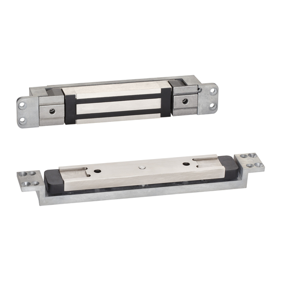
gravity force shear locks:
mortise & surface mount
Hide thumbs
Also See for GF3000:
- Installation instructions (2 pages) ,
- Installation instructions manual (13 pages)
Table of Contents

Related Manuals for Schlage GF3000


Summary of Contents for Schlage GF3000
- Page 1 *30500* GF3000 30500 INSTALLATION MANUAL Models Covered: Standard, TRD, BRD, SM, and TJ Gravity Force Shear Locks: Mortise & Surface Mount Customer Service © Allegion 2014 Printed in U.S.A. 1-877-671-7011 www.allegion.com/us 30500 1/15-f...
-
Page 2: Table Of Contents
GF3000 SERIES INSTALLATION MANUAL Table of Contents Table of Contents GF3000 SERIES INSTALLATION MANUAL Table of Contents Confirming the Box Contents ........................3 Introduction ...............................4 Tools and Materials Needed Not Included in Box ..................4 Contact Information: ..........................4 Specificati ons: ............................5 Operation: ........................ -
Page 3: Confirming The Box Contents
GF3000 SERIES INSTALLATION MANUAL Confirming the Box Contents Confirming the Box Contents Confirming the Box Contents - MAGNETIC COIL ASSEMBLY - ARMATURE - ARMATURE MOUNTING ASSEMBLY - MOUNTING TABS - HEX WRENCH - SHIM PLATE - HARDWARE PACK - MAGNETIC COIL HOUSING... -
Page 4: Introduction
GF3000 SERIES INSTALLATION MANUAL Introduction / Tools and Materials Needed / Contact Info Introduction Introduction / Tools and Materials Needed / Contact Info This manual covers the complete installation and wiring instructions for the following GF3000 Series models: MORTISE: GF3000 (Standard model) •... -
Page 5: Specifications
Certifications/Compliance ... . . UL# R12092; MEA# 222-96-E; CSFM# 3774-0544:107 Shipping Weight ..... GF3000 - 6 Pounds; GF3000TRD & BRD - 8 Pounds Dimensions - Mortise Mount . -
Page 6: Preparing The Frame And Door
The figure below shows the centerline scheme for a stan- dard GF3000 and a GF3000TRD. Note that centerlines for magnet (M1 and M2) are directly above centerlines for armature assembly (A1 and A2) thus forming a vertical axis (AM). - Page 7 GF3000 SERIES INSTALLATION MANUAL Installing a GF3000 Series Lock 1) Establish Frame and Door Centerlines (BRD): For proper operation, it’s critical to establish centerlines of the magnet and armature • assembly that line up to form a vertical axis. The figure below shows the centerline scheme for a GF3000BRD.
-
Page 8: Installing The Lock - Standard, Trd, Tj, Sm
GF3000 SERIES INSTALLATION MANUAL Installing a GF3000 Series Lock Installing the Lock - Standard, TRD, TJ, SM 1) Mounting Tabs (Standard, TRD): Secure two mounting tabs (a) to ends of lock cutout in frame. Mounting tabs can be installed upside-... -
Page 9: Frame Prep (Standard And Trd)
GF3000 SERIES INSTALLATION MANUAL Installing a GF3000 Series Lock • FRAME AND DOOR PREP - Standard, TRD, TJ, SM 3) Frame Prep (Standard and TRD): The frame prep is the same for the Standard and the TRD models. The door prep for the •... -
Page 10: Door Prep (Standard And Trd)
GF3000 SERIES INSTALLATION MANUAL Installing a GF3000 Series Lock 4) Door Prep (Standard and TRD): DOOR PREP Hollow Metal or • Aluminum Depth: flush to 1/4” • DOOR PREP Hollow Metal or • Aluminum Depth: 1/4” to 1” • DOOR PREP Hollow Metal or •... - Page 11 GF3000 SERIES INSTALLATION MANUAL Installing a GF3000 Series Lock Standard and TRD Door Prep (continued): DOOR PREP Hollow Metal or • Aluminum Depth: 1-3/4” to 2-1/2” • DOOR PREP Wood • MINIMUM 1-7/8” DOOR THICKNESS DOOR PREP - TRD Hollow Metal or •...
-
Page 12: Template Information (Tj)
GF3000 SERIES INSTALLATION MANUAL Installing a GF3000 Series Lock 5) Template information (TJ): All dimensions in inches. NOTE: Hole (a) - size and type depends on door type and mounting style. 6) Template information (SM): All dimensions in inches. LEFT HAND... -
Page 13: Mounting The Lock - Standard, Trd, Tj, Sm
> DO NOT COMPLETELY TIGHTEN AT THIS TIME 4) Install Magnet: Make final wiring connections (see Wiring Diagram: on • page 21 . Insert GF3000 magnet (a) into magnet housing. • Using four, 10-24 x 1/2 screws (b), secure mounting • spacer and armature housing onto door. -
Page 14: Installing The Lock - Brd
GF3000 SERIES INSTALLATION MANUAL Installing a GF3000 Series Lock Installing the Lock - BRD • INSTALLING THE MAGNET AND ARMATURE 1) Preparing the Floor for the GF3000BRD Magnet: Since the GF3000BRD magnet is installed in the floor directly below the bottom rail of the door, a threshold box (that will hold the magnet) that is inset into a pocket (a) in the floor, and a trench (b) for the electrical conduit is required. -
Page 15: Installing The Gf3000Brd Threshold Box
GF3000 SERIES INSTALLATION MANUAL Installing a GF3000 Series Lock 2) Installing the GF3000BRD Threshold Box: After the pocket and trench are created, do the following: Feed 1/2" conduit into either 7/8" diameter hole in threshold box. • Secure conduit with nut. -
Page 16: Mounting The Gf3000Brd Magnet Into The Threshold Box
GF3000 SERIES INSTALLATION MANUAL Installing a GF3000 Series Lock 5) Mounting the GF3000BRD Magnet Into the Threshold Box: Mount magnet (a) to box (b) by placing two speed nuts (c) per slot, side by side in • flanges of box. -
Page 17: Wiring The Lock-Standard, Trd, Tj, Sm
1) Wiring Diagram: 2) Standard Features: Operating Voltage The GF3000 will operate only on filtered and regulated 12 or 24 volts DC. Automatic voltage selection circuitry is standard, eliminating the need for a voltage selection switch. Automatic Relock Switch (ARS) A built-in relock switch requires the door to be in the closed position before the magnet can be energized. -
Page 18: Wiring The Lock - Brd
GF3000 SERIES INSTALLATION MANUAL Installing a GF3000 Series Lock Wiring the Lock - BRD 1) Wiring Diagram: Automatic Relock Switch (ARS) IMPORTANT: DO NOT CUT YELLOW WIRE ON CONTROL MODULE. FILTERED, REGULATED 2) Standard Features: Operating Voltage The GF3000BRD will operate only on filtered and regulated 12 or 24 volts DC. Automatic voltage selection circuitry is standard, eliminating the need for a voltage selection switch. -
Page 19: Door Status Monitor
GF3000 SERIES INSTALLATION MANUAL Installing a GF3000 Series Lock Door Status Monitor (DSM) - GF3000BRD Hole for switch: 1” diameter in frame. • Hole for magnet: • > (a) Wood or Aluminum doors - 3/8” diameter > (b) Hollow metal doors - 1” diameter Installation of magnet and switch must be concentric (common centerline). -
Page 20: Air Gap Adjustment
GF3000 SERIES INSTALLATION MANUAL Installing a GF3000 Series Lock Air Gap Adjustment 1) Set Armature Height: Using the provided 7/32 hex wrench, raise • or lower the armature as needed. > Clearance between magnet and armature is recommended to be 1/8”, and must be less than 1/4”.