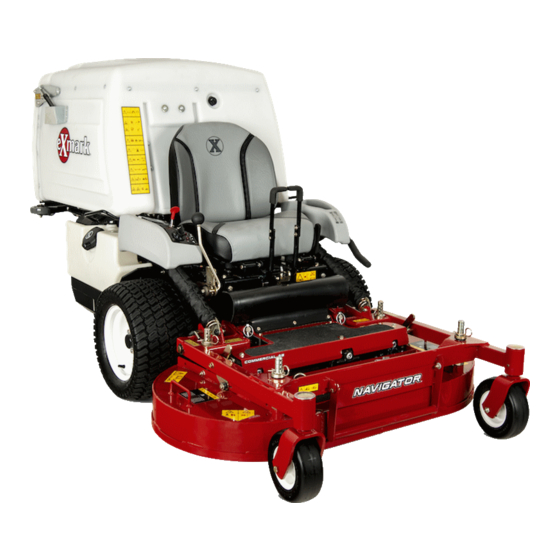
Exmark NAVIGATOR Operator's Manual
Hide thumbs
Also See for NAVIGATOR:
- Operator's manual (48 pages) ,
- Parts manual (28 pages) ,
- Setup instructions (4 pages)
Table of Contents
Advertisement
Advertisement
Table of Contents

Related Manuals for Exmark NAVIGATOR


Summary of Contents for Exmark NAVIGATOR
- Page 1 NAVIGATOR ® For Serial Nos. 400,000,000 & Higher Part No. 4503-256 Rev. A...
- Page 2 SAE testing and gross/net power rating standards (J1940, J1995, J1349). Exmark reserves the right to make changes or add improvements to its products at any time without incurring any obligation to make such changes to products manufactured previously.
-
Page 3: Introduction
All Exmark parts are thoroughly tested and inspected before leaving the factory, however, attention is required on your part if you are to obtain the fullest measure of satisfaction and performance. -
Page 4: Table Of Contents
Contents Adjust Safety Switch ........42 Parking Brake Adjustment ......42 Reverse Stop Rod Adjustment......43 Introduction ............3 Adjust Speed Control Lever Tension ....44 Safety ..............5 Speed Control Linkage Adjustment....44 Safety Alert Symbol ......... 5 Tracking Adjustment ........45 Safe Operating Practices ........5 PTO Drive Pulley Alignment ......45 Safety and Instructional Decals ......11 Pump Drive Pulley Alignment......46... -
Page 5: Safety
• Become familiar with the safe operation of the Exmark designed and tested this lawn mower to offer equipment, operator controls, and safety signs. reasonably safe service; however, failure to comply • All operators and mechanics should be trained. - Page 6 Safety bones, and other foreign objects which can be DANGER thrown by the machine and may cause personal In certain conditions during fueling, static injury to the operator or bystanders. electricity can be released causing a spark which can ignite gasoline vapors. A fire or DANGER explosion from gasoline can burn you and In certain conditions gasoline is extremely...
- Page 7 • Stop engine, wait for all moving parts to stop, and engage parking brake: WARNING – Before refueling. Operating a Navigator tractor without an – Before dumping the grass catcher. approved Exmark front mount attachment increases the possibility of operator entanglement WARNING in drive wheels or forward tip over.
-
Page 8: Slope Operation
Note: A 2–post foldable ROPS (Rollover Protection System) is available for the Navigator as an accessory. A ROPS is recommended if you will be mowing next to drop-offs, near water, or on steep banks which could result in a rollover. -
Page 9: Maintenance And Storage
Safety The California Code of Regulations requires ROPS DANGER and seatbelt (if equipped) on all commercial mowers Charging or jump starting the battery may effective March 1, 2011. Because all Navigators were produce explosive gases. Battery gases can designed with an optional ROPS accessory, they are explode causing serious injury. - Page 10 Unauthorized modifications to the original equipment or failure to use original Exmark parts could lead to serious injury or death. Unauthorized changes to the machine, engine, fuel or venting system, may violate applicable...
-
Page 11: Safety And Instructional Decals
Exmark equipment dealer or labels. distributor or from Exmark Mfg. Co. Inc. • Replace all worn, damaged, or missing safety • Safety signs may be affixed by peeling off the signs. - Page 12 Safety 116-8936 1. Danger-Do Not operate with deck in tilt-up position. 115-4212 1. Hydraulic oil level 3. Warning—do not touch the hot surface. 2. Read the Operator's Manual. 116-8941 116-8934 1. Warning-Disengage 2. Height of cut. blade clutch, shut off engine, and remove key before making adjustments, servicing,...
- Page 13 Safety 116-8946 1. Rotate counterclockwise 3. Unlock to push machine to release 116-9375 2. Rotate clockwise to lock 4. Read the instructions before servicing or All Units Except EFI performing maintenance. 1. Neutral 3. Fast 2. Reverse 4. Slow 116-9049 1.
- Page 14 Safety 120-0625 1. Pinch point, hand-keep hands away. 126-7442 All Units Except EFI 1. Fast 4. Neutral 2. Machine speed 5. Engine oil temperature light 126-4207 3. Slow 1. Refer to the Operator’s manual for adjustment procedure. When PTO is engaged, idler arm position must be in hatched area or adjustment is required.
- Page 15 Safety Message Display 1. Hopper up indicator 5. Parking brake 2. Battery 6. Neutral 3. Hour meter 7. Operator presence switch 4. PTO 116-9044 1. Read the Operator’s Manual before performing any 8. Grease deck lock mechanism every 100 hours. maintenance.
- Page 16 Safety Molded into Front of Hopper 1. Warning-Read the Operator’s Manual. Do Not operate this 5. Warning-Stay away from moving parts; keep all guards machine unless you are trained. Wear hearing protection. in place. Stop engine and remove key before adjusting, servicing, or cleaning.
-
Page 17: Specifications
Manual • Operator must be in seat when PTO is engaged, • Engine Oil Type: Exmark 4–Cycle Premium brake is disengaged, or speed control lever is Engine Oil moved out of neutral or engine will stop. -
Page 18: Dimensions
• Wheel Motors: Hydro Gear planetary reduction – Heavy-duty cast iron, spiral bevel gearbox is motors. final drive to blades. • Hydraulic Oil Type: Use Exmark Premium Hydro – Gearbox Oil Type: Mobil SHC (synthetic) oil. 75W-90 gear lube. • Hydraulic Oil Capacity: 6.0 qt. (5.7 L) •... -
Page 19: Torque Requirements
Product Overview Wheel Base: (Center of Drive Wheel Product Overview to Center of Rear Caster Wheel) 42 inch Deck 48 inch Deck 44.2 inches (112.3 cm) 44.2 inches (112.3 cm) Curb Weight: 42 inch Deck 48 inch Deck 1140 lb (517 kg) 1170 lb (531 kg) Torque Requirements Bolt Location... -
Page 20: Operation
Operation Operation Note: Determine the left and right sides of the machine from the normal operating position. Controls Steering Levers Located in the center in front of the seat. Pulling back on the steering levers, progressively slows, then reverses the direction of travel of the Figure 5 respective drive wheels. -
Page 21: Hour Meter
Operation the next position to engage the starter (key must be pushed without the engine running. Tilt seat up to held against spring pressure in this position). gain access to pumps. Note: Brake must be engaged, speed control lever With a 7/16 wrench, turn both valves one turn rearward (neutral position) and PTO disengaged to counterclockwise to release drive system. -
Page 22: Pre-Start
Operation or fault within the system is detected, the malfunction On a warm engine, leave the choke in the “OFF” indicator light (MIL) is illuminated. The MIL is the position. light located in the right console panel to the left of 6. -
Page 23: Stopping The Engine
Operation Disengaging the PTO Driving in Reverse 1. Set the throttle to the “MIDWAY” position. 1. To move rearward in a straight line applying equal pressure pull both steering levers rearward. 2. Push PTO lever down to the “STOP” position stopping the PTO and blower. - Page 24 Always operate mower with locking pins securely latched. Adjusting Fill Reduction System (FRS) Baffles The Navigator’s exclusive Fill Reduction System has been designed to allow you to reduce the amount of clippings collected by varying degrees. Advantages include less frequent emptying of the hopper and return of nutrients to the soil.
- Page 25 Operation 2. Remove hair pins and clevis pins from both sides of the PTO guard (see Figure 9). Fold guard forward. Figure 9 3. Loosen nyloc nuts on the rear studs of the FRS baffles. Figure 11 1. Baffles shown in closed position 2.
- Page 26 Operation Removing the Deck WARNING Operating a Navigator tractor without an approved Exmark front mount attachment increases the possibility of operator entanglement in drive wheels or forward tip over. Entanglement or tip-over could cause serious injury or death. When operating a Navigator tractor without...
- Page 27 1. Stop engine, wait for all moving parts to stop and remove key. Engage parking brake. 2. Roll the mower deck up to the Navigator tractor with the discharge tube down, making sure the deck springs are located above the drive wheel and below the console on each side.
-
Page 28: Transporting
Operation 7. Install springs onto the spring anchor pins under the left and right consoles and secure with a washer and hairpin (see Figure 12). 8. Un-latch deck from raised position, slowly lower deck to ground and lock deck locking pins on each side Lowering the Deck to the Operation Position section in Operation. - Page 29 Operation WARNING Loading a unit on a trailer or truck increases the possibility of tip-over. Tip-over could cause serious injury or death. • Use extreme caution when operating a unit on a ramp. • Use only a single, full width ramp; Do Not use individual ramps for each side of the unit.
-
Page 30: Maintenance
Maintenance Maintenance Note: Determine the left and right sides of the machine from the normal operating position. WARNING WARNING While maintenance or adjustments are being The engine can become very hot. Touching a hot made, someone could start the engine. engine can cause severe burns. -
Page 31: Periodic Maintenance
“FULL” time without recharging them will result in reduced mark on the dipstick. Exmark 4-Cycle Premium performance and service life. To preserve optimum Engine Oil is recommended; refer to the Engine... -
Page 32: Recommended Jump Starting Procedure
Maintenance settings). This is especially important on Kohler DANGER EFI (Electronic Fuel Injection) units. Failure to Jump starting a weak battery that is cracked, do so may damage the ECU (Electronic Control frozen, has low electrolyte level, or an Unit). open/shorted battery cell, can cause an Percent Voltage... -
Page 33: Check Mower Blades
6. Discharged battery • Replace the blade bolt after striking a 7. Engine block foreign object. • Use only genuine Exmark replacement 4. Connect the other end of the positive cable to the parts. positive terminal of the booster battery. -
Page 34: Check Safety Interlock System
2. Visually inspect machine for any loose hardware around oil filter and unscrew filter to remove. or any other possible problem. Tighten hardware Before reinstalling new filter, apply a thin coating or correct the problem before operating. of Exmark 4–Cycle Premium Engine Oil on the... -
Page 35: Check Hydraulic Oil Level
7. If the dipstick oil level does not register on the WARNING dipstick, add Exmark Premium Hydro Oil. Do Oil spilled or vented from an overfilled hydraulic Not overfill. -
Page 36: Change Gearbox Oil
Maintenance Check Gearbox Oil Belt Replacement and Pump Drive Belt Replacement sections for belt replacement. Service Interval: Every 100 hours 1. Stop engine, wait for all moving parts to stop, and Change Gearbox Oil remove key. Engage parking brake. Service Interval: After the first 50 hours 2. -
Page 37: Lubricate Rear Caster Wheel Hubs
6. Pack the bearings with a NLGI grade #1 multi-purpose grease. 7. Insert one bearing, one new seal into the wheel. Note: Seals (Exmark PN 103-0063) must be replaced. 8. If the axle assembly has had both spacer nuts removed (or broken loose), apply a thread locking adhesive to one spacer nut and thread onto the Deck shown for reference only. -
Page 38: Lubricate Brake Handle Pivot
(Every 250 hours/Yearly if Lubricate Steering Linkage using Mobil 1 15W50) Rod Ends Note: Use only Exmark Part No. 109-4180 for Summer use above 32°F (0°C) or P/N 1-523541 Service Interval: Every 160 hours for Winter use below 32°F (0°C). (Refer to the 1. -
Page 39: Check Wheel Hub Locknuts
Torque to 85-105 ft-lb (122-129 N-m) cross pattern. Important: Before reinstalling new filter, fill it with Exmark Premium Hydro oil and apply Fuel Tank — Mounting a thin coat of oil on the surface of the rubber Hardware Specifications seal. -
Page 40: Adjustments
Maintenance Adjustments 2. With engine “off ”, engage PTO lever, then remove the hairpin and clevis pin at the bottom Note: Disengage PTO, shut off engine, wait for of the PTO brake band. all moving parts to stop, engage parking brake, and 3. -
Page 41: Pump Drive Belt Replacement
Maintenance Figure 26 1. Pump Drive Belt 4. Pump 2. Pump 5. Idler 3. Idler 6. Engine Figure 25 1. Tension Arm 5. Reinstall PTO Belts as stated in the PTO Belt 2. Loosen jam nuts Replacement section 3. When PTO is engaged, align top of idler arm with bottom of notch on tension arm, as shown. -
Page 42: Adjust Safety Switch
Maintenance Adjust Safety Switch Adjust all safety switches so plunger extends 3/16 inch to 1/4 inch (4.8 mm-6.4 mm) from switch body when plunger is compressed (see Figure 28). Figure 28 Figure 29 1. 3/16 inch to 1/4 inch (4.8 mm-6.4 mm) 1. -
Page 43: Reverse Stop Rod Adjustment
Maintenance Figure 31 1. 8.92–9.16 inches 2. Nuts (22.7–23.3 cm) 7. Engage and disengage the brakes to check for proper engagement and disengagement. Readjust Figure 30 if necessary. When the brakes are disengaged, 1. Parking brake 4. Vertical spring assembly there should be little to no free play in the brake 2. -
Page 44: Adjust Speed Control Lever Tension
Maintenance Figure 33 Figure 32 1. Nut 4. Friction disc 1. Parking brake 4. Speed control lever 2. Spring disc washers 5. Speed control friction 2. Nut 5. Clevis pin and stop rod bracket 3. Steering lever 3. Speed control friction 6. -
Page 45: Tracking Adjustment
Maintenance Set neutral: 9. Stop engine and wait for all moving parts to stop. Remove jumper wire from wire harness connector 1. Remove the electrical connection from the seat and plug connector into seat switch. safety switch, located directly in front of the seat switch assembly. -
Page 46: Pump Drive Pulley Alignment
Maintenance Caster Pivot Bearings Pre-Load Adjustment Remove dust cap from caster and tighten nyloc nut until washers are flat. Back off 1/4 of a turn to properly set the pre-load on the bearings. If disassembled, make sure the spring disc washers are reinstalled as shown in Figure 36 and Figure 37. -
Page 47: Pto Brake Spring Adjustment
Maintenance Loosen six door hinge nuts (see Figure 38). Open door and place a 3/8 inch rubber strip or 3/8 inch diameter hose between the hopper and hopper door (see Figure 38). Close door and push tight against hopper. Tighten hinge hardware. Open hopper door and remove rubber strip. -
Page 48: Cleaning
Maintenance Cleaning Clean Debris From Machine Service Interval: Before each use or daily Clean Engine and Exhaust 1. Stop engine, wait for all moving parts to stop, and System Area remove key. Engage parking brake. 2. Clean off any oil, debris, or grass build-up on the Service Interval: Before each use or daily machine, especially around the fuel tank, around (May be required more... -
Page 49: Battery Disposal
Maintenance Battery Disposal DANGER Battery electrolyte contains sulfuric acid, which is poisonous and can cause severe burns. Swallowing electrolyte can be fatal or if it touches skin can cause severe burns. • Wear safety glasses to shield eyes, and rubber gloves to protect skin and clothing when handling electrolyte. -
Page 50: Troubleshooting
Troubleshooting Troubleshooting Important: It is essential that all operator safety mechanisms be connected and in proper operating condition prior to mower use. When a problem occurs, do not overlook the simple causes. For example: starting problems could be caused by an empty fuel tank. The following table lists some of the common causes of trouble. - Page 51 Troubleshooting Problem Possible Cause Corrective Action Engine overheats. 1. Engine load is excessive. 1. Reduce the ground speed. 2. Oil level in the crankcase is low. 2. Add oil to the crankcase. 3. Cooling fins and air passages for the 3.
-
Page 52: Schematics
Schematics Schematics Electrical Diagram — All Units Except Kohler EFI... - Page 53 Schematics Electrical Diagram — Kohler EFI...
- Page 54 Schematics Electrical Schematic — All Units Except Kohler EFI...
- Page 55 Schematics Electrical Schematic — Kohler EFI...
- Page 56 Schematics Hydraulic Diagram...
- Page 57 No Claim of breach of warranty shall be cause for cancellation There are no other express warranties except for engine and or rescission of the contract of sale of any Exmark mower. special emission system coverage. All implied warranties of merchantability (that the...
- Page 59 G011841 Figure 41 This page may be copied for personal use. 1. The maximum slope you can safely operate the machine on is 15 degrees. Use the slope indicator to determine the degree of slope of hills before operating. Do Not operate this machine on a slope greater than 15 degrees. Fold along the appropriate line to match the recommended slope.
- Page 60 Pack) or Fill in Below Engine Model No. and Spec. No. Model No. Engine Serial No. (E/No) Serial No. ©2016 Exmark Mfg. Co., Inc. Part No. 4503-256 Rev. A Industrial Park Box 808 (402) 223-6375 Beatrice, NE 68310 Fax (402) 223-5489...