Table of Contents
Advertisement
Advertisement
Table of Contents

Related Manuals for Exmark NAVIGATOR 4500-367


Summary of Contents for Exmark NAVIGATOR 4500-367
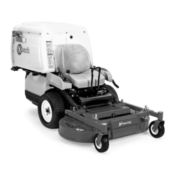
- Page 1 NAVIGATOR ® For Serial Nos. 790,000 & Higher Part No. 4500-367 Rev. A...
- Page 2 Replacements may be ordered through the engine manufacturer. Exmark reserves the right to make changes or add improvements to its products at any time without incurring any obligation to make such changes to products manufactured previously.
-
Page 3: Introduction
All Exmark parts are thoroughly tested and inspected before leaving the factory, however, attention is required on your part if you are to obtain the fullest measure of satisfaction and performance. -
Page 4: Table Of Contents
Contents Introduction ... 3 Safety ... 5 Safety Alert Symbol ... 5 Safe Operating Practices ... 5 Safety and Instructional Decals ... 10 Specifications ... 13 Model Numbers ... 13 Systems ... 13 Dimensions... 14 Torque Requirements ... 15 Product Overview ... 15 Operation ... -
Page 5: Safety
• Evaluate the terrain to determine what accessories and attachments are needed to properly and safely perform the job. Only use accessories and attachments approved by Exmark. • Wear appropriate clothing including safety glasses, substantial footwear, long trousers, and hearing protection. - Page 6 Safety DANGER In certain conditions gasoline is extremely flammable and vapors are explosive. A fire or explosion from gasoline can burn you, others, and cause property damage. • Fill the fuel tank outdoors in an open area, when the engine is cold. Wipe up any gasoline that spills.
- Page 7 Entanglement or tip-over could cause serious injury or death. When operating a Navigator tractor without an approved Exmark front mount attachment, observe the following: • Keep feet and clothing away from tires. • Limit operation to minimum required to install a different front mount attachment.
-
Page 8: Slope Operation
Safety • Stop engine, wait for all moving parts to stop, and engage parking brake: – Before refueling. – Before dumping the grass catcher. WARNING Hands, feet, hair, clothing, or accessories can become entangled in rotating parts. Contact with the rotating parts can cause traumatic amputation or severe lacerations. -
Page 9: Maintenance And Storage
• Avoid sudden starts when mowing downhill. Mower may tip forwards. • Be aware that operating on wet grass, across steep slopes or downhill may cause the mower to lose traction. Loss of traction to the drive wheels may result in sliding and a loss of braking and steering. •... -
Page 10: Safety And Instructional Decals
103-8425 • New safety signs may be obtained from your authorized Exmark equipment dealer or distributor or from Exmark Mfg. Co. Inc. • Safety signs may be affixed by peeling off the backing to expose the adhesive surface. Apply only to a clean, dry surface. Smooth to remove any air bubbles. - Page 11 103-9034 103-9724 109-4273 Safety 109-4638 109-7318 116-0404...
- Page 12 Safety 116-1175 Molded in LH Console Molded into Front of Hopper...
-
Page 13: Specifications
Hydrostatic Ground Drive System • Hydrostatic Pumps: Two Hydro Gear variable displacement piston pumps. • Wheel Motors: Hydro Gear planetary reduction motors. • Hydraulic Oil Type: Use Exmark Premium Hydro oil. • Hydraulic Oil Capacity: 4.0 qt. (3.8 L) Specifications... -
Page 14: Dimensions
Specifications • Hydraulic Filter: Replaceable cartridge type. – Summer use above 32°F (0°C): P/N 109-0071: 25 microns, 10 psi bypass – Winter use below 32°F (0°C): P/N 1-523541: 40 microns, 18 psi bypass • Speeds: – 0-7.0 mph (11.3 km/hr) forward. –... -
Page 15: Torque Requirements
Curb Weight: 42 inch Deck 48 inch Deck 850 lb (386 kg) 1145 lb (519 kg) Torque Requirements Bolt Location Torque Blade Mounting Bolt 85-110 ft-lb (115-149 N-m) Engine Mounting Bolts 30-35 ft-lb (41-47 N-m) Wheel Lug Nuts 90-95 ft-lb (122-129 N-m) Wheel Motor Mounting 72-77 ft-lb (98-104 N-m) Bolts... -
Page 16: Operation
Operation Operation Note: Determine the left and right sides of the machine from the normal operating position. Controls Steering Levers Located in the center in front of the seat. Pulling back on the steering levers, progressively slows, then reverses the direction of travel of the respective drive wheels. -
Page 17: Pre-Start
Drive Wheel Release Valves Located on the top left front corner of hydrostatic pumps. Drive wheel release valves are used to release the hydrostatic drive system to allow the machine to be pushed without the engine running. Tilt seat up to gain access to pumps. -
Page 18: Stopping The Engine
Operation Important: Do Not crank the engine continuously for more than ten seconds at a time. If the engine does not start, allow a 60 second cool-down period between starting attempts. Failure to follow these guidelines can burn out the starter motor. 7. -
Page 19: Transporting
To turn left or right, pull one of the steering levers back toward neutral in the direction desired. The machine will move faster the farther the speed control lever is moved away from neutral. 4. To stop, pull the speed control lever back to the neutral position. - Page 20 Operation WARNING Loading a unit on a trailer or truck increases the possibility of tip-over. Tip-over could cause serious injury or death. • Use extreme caution when operating a unit on a ramp. • Use only a single, full width ramp; Do Not use individual ramps for each side of the unit.
-
Page 21: Maintenance
Maintenance Note: Determine the left and right sides of the machine from the normal operating position. WARNING While maintenance or adjustments are being made, someone could start the engine. Accidental starting of the engine could seriously injure you or other bystanders. Remove the key from the ignition switch, engage parking brake, and pull the wire(s) off the spark plug(s) before you do any... -
Page 22: Periodic Maintenance
Maintenance Maintenance Service Maintenance Procedure Interval • Check the battery charge. Monthly • Lubricate grease fittings. Yearly • Lubricate the caster wheel hubs. Periodic Maintenance Check Engine Oil Level Service Interval: Before each use or daily 1. Stop engine and wait for all moving parts to stop. Make sure unit is on a level surface. -
Page 23: Check Safety Interlock System
1/2 second has elapsed. Note: If machine does not pass any of these tests, do not operate. Contact your authorized EXMARK SERVICE DEALER. Important: It is essential that operator safety mechanisms be connected and in proper operating condition prior to use for mowing. -
Page 24: Check Hydraulic Oil Level
3. Clean area around hydraulic reservoir cap and remove cap. Oil level should be to the top of the baffle inside the tank. If not, add oil. Use only Exmark Premium Hydro oil. Replace hydraulic reservoir cap and tighten until snug. Do Not overtighten. Do Not overfill. -
Page 25: Lubricate Rear Caster Wheel Hubs
6. Pack the bearings with a NGLI grade #1 multi-purpose grease. 7. Insert one bearing, one new seal into the wheel. Note: Seals (Exmark PN 103-0063) must be replaced. 8. If the axle assembly has had both spacer nuts removed (or broken loose), apply a thread locking adhesive to one spacer nut and thread onto the axle with the wrench flats facing outward. -
Page 26: Lubricate Brake Handle Pivot
Maintenance 11. Insert the second bearing and new seal into the wheel. 12. Apply a thread locking adhesive to the 2nd spacer nut and thread onto the axle with the wrench flats facing outward. 13. Torque the nut to 75-80 in-lb (8-9 N-m), loosen, then re-torque to 20-25 in-lb (2-3 N-m). -
Page 27: Change Hydraulic System Filter
(Every 250 hours/Yearly if using Mobil 1 15W50) Note: Use only Exmark Part No. 109-0071 for Summer use above 32°F (0°C) or P/N 1-523541 for Winter use below 32°F (0°C). (Refer to the Hydrostatic Ground Drive System section in Specifications for filter specifications.) -
Page 28: Check Wheel Hub Locknuts
Maintenance Check Wheel Hub Locknuts Service Interval: After the first 100 hours Every 500 hours thereafter Torque to 210–250 ft-lb (285–339 N-m). Check Wheel Lug Nuts Service Interval: After the first 100 hours Every 500 hours thereafter Torque to 90–95 ft-lb (122–129 N-m) cross pattern. Fuel Tank —... -
Page 29: Pump Drive Belt Replacement
10. Re-install clevis pin and hairpin to secure brake band. 11. Engage the PTO lever. 12. Loosen the jam nuts and adjust linkage until the top of the idler arm is aligned with the bottom of notch on tension arm as shown in Figure 9. Figure 9 1. -
Page 30: Adjust Safety Switch
Maintenance Adjust Safety Switch Adjust all safety switches so plunger extends 3/16 inch to 1/4 inch (4.8 mm-6.4 mm) from switch body when plunger is compressed (see Figure 12). Figure 12 1. 3/16 inch to 1/4 inch (4.8 mm-6.4 mm) Brake Adjustment Check to make sure each brake is adjusted properly. -
Page 31: Speed Control Linkage Adjustment
loose enough to be moved comfortably by the operator. Figure 15 1. Speed Control Lever 3. Spring disc washers 2. Friction Plate 4. Hex locknut Speed Control Linkage Adjustment WARNING Engine must be running and drive wheels must be turning so motion control adjustment can be performed. -
Page 32: Set Forward Stop Bolt
Maintenance across the terminals in the connector of the wiring harness. 3. Start the engine. 4. Run the unit at least 5 minutes with the speed control lever at full forward speed to bring hydraulic system oil up to operating temperature. -
Page 33: Tracking Adjustment
Figure 19 1. To increase steering responsiveness hook pump control sprints directly on anchor bolt. To decrease steering responsiveness hook pump control springs on anchor tabs as shown. Tracking Adjustment See Motion Control Linkage Adjustment section PTO Drive Pulley Alignment PTO drive pulley alignment is necessary for any of the following conditions: •... -
Page 34: Rear Caster Pivot Bearings Pre-Load Adjustment
Maintenance Rear Caster Pivot Bearings Pre-Load Adjustment Remove dust cap from caster and tighten nyloc nut until washers are flat. Back off 1/4 of a turn to properly set the pre-load on the bearings. If disassembled, make sure the spring disc washers are reinstalled as shown in Figure 21. -
Page 35: Cleaning
Cleaning Clean Engine and Exhaust System Area Service Interval: Before each use or daily (May be required more often in dry or dirty conditions.) CAUTION Excessive debris around the engine cooling air intake and inside of the pump drive belt compartment and damaged or missing rubber baffles can cause the engine and hydraulic system to overheat which can create a fire hazard. -
Page 36: Troubleshooting
Troubleshooting Troubleshooting Important: It is essential that all operator safety mechanisms be connected and in proper operating condition prior to mower use. When a problem occurs, do not overlook the simple causes. For example: starting problems could be caused by an empty fuel tank. The following table lists some of the common causes of trouble. - Page 37 Problem Engine overheats. Mower pulls left or right (with levers fully forward). Machine does not drive. Abnormal vibration. Possible Cause 1. Engine load is excessive. 2. Oil level in the crankcase is low. 3. Cooling fins and air passages for the engine are plugged.
-
Page 38: Schematics
Schematics Schematics BLACK BLACK BLACK BLACK BROWN BROWN BLUE BLACK PINK BLACK ORANGE ORANGE ORANGE PINK PINK PINK ORANGE ORANGE Electrical Diagram BLACK PURPLE GREEN GREEN WHITE DK.GREEN GREEN BLACK BLACK STRIPE ORANGE/BLACK GREEN YELLOW BLUE BLUE GREEN GRAY BLUE GREEN GREEN BLUE... - Page 39 Electrical Logic Schematic BLACK BLACK BLACK BLACK GREEN BLACK BLUE BLACK PINK PINK ORANGE PINK BLACK PINK ORANGE ORANGE GREEN GREEN GREEN GREEN WHITE GREEN BLACK BLACK GREEN GREEN STRIPE ORANGE/BLACK YELLOW BLUE BLUE GREEN BLUE GRAY GREEN GREEN BLUE BLUE BROWN BLACK...
-
Page 40: Hydraulic Diagram
Schematics HIGH PRESSURE FORWARD Hydraulic Diagram BYPASS VALVE HIGH PRESSURE REVERSE HIGH PRESSURE CHARGE PUMP CASE DRAIN BYPASS VALVE HIGH PRESSURE REVERSE HIGH PRESSURE FORWARD G006950... - Page 41 • Attorney's fees. No Claim of breach of warranty shall be cause for cancellation or rescission of the contract of sale of any Exmark mower. All implied warranties of merchantability (that the product is fit for ordinary use) and fitness for use (that the product is fit for a particular purpose) are limited to the duration of the express warranty.
- Page 44 SEE EXMARK’S COMPLETE LINE OF ACCESSORIES AND OPTIONS MID-MOUNT RIDING ACCESSORIES AND OPTIONS CUSTOM RIDE SEAT SUSPENSION SYSTEM FULL SUSPENSION SEAT DECK LIFT ASSIST KIT HITCH KIT LIGHT KIT V POWER PORT MICRO-MULCH SYSTEM OUT-FRONT RIDING ACCESSORIES AND OPTIONS CUSTOM RIDE SEAT SUSPENSION SYSTEM...