Exmark CD42CD Operator's & Parts Manual
Exmark navigator operator's manual
Hide thumbs
Also See for CD42CD:
- Operator's manual (24 pages) ,
- Setup instructions (4 pages) ,
- Parts manual (12 pages)
Advertisement
Advertisement

Related Manuals for Exmark CD42CD


Summary of Contents for Exmark CD42CD
- Page 1 For Serial Nos. 510,000 & Higher Part No. 103-8614 Rev. A...
- Page 2 3. Exmark being unable to ship the part and the Exmark parts order is received by 3:00 p.m., central time, Exmark pays for the part and freight. 4. If the part does not arrive overnight due to the shipper (UPS), the shipper pays for the freight and Exmark pays for the part.
- Page 3 POTENTIAL HAZARD ♦ This product is a piece of power equipment. WHAT CAN HAPPEN ♦ Failure to follow safe operating practices can result in serious operator injury or even death. HOW TO AVOID THE HAZARD ♦ Keep all shields, guards, and safety devices (especially the grass discharge system) in place and in proper working condition.
- Page 4 If additional information is needed, or should you require trained mechanic service, contact your authorized Exmark equipment dealer or distributor. All Exmark equipment dealers and distributors are kept informed of the latest methods of servicing and are equipped to provide prompt and efficient service in the field or at their service stations.
-
Page 5: Table Of Contents
1. SAFETY Safety Alert Symbol ... 1 Training ... 1 Preparation... 1-2 Operation ... 2 Maintenance & Storage ... 2 Safety Signs ... 2-3 2. SPECIFICATIONS Model Number ... 4 Dimensions... 4 Torque Requirements... 4 3. ASSEMBLY INSTRUCTIONS Uncrate Deck... 4 Assemble Discharge Chute ... -
Page 6: Safety Alert Symbol
MAY result in minor or moderate injury. 1.2 TRAINING 1.2.1 Regard the Exmark mower as a piece of power equipment and teach this regard to all who operate this unit. 1.2.2 Before operating your mower, read the Navigator tractor and cutting deck manual instructions carefully. -
Page 7: Operation
Safety signs must be replaced if they are missing or illegible. 1.6.3 When new components are installed, be sure that current safety signs are affixed to the replaced components. 1.6.4 New safety signs may be obtained from Exmark Mfg. Co. Inc. WARNING... - Page 8 Apply only to a clean, dry surface. Smooth to remove any air bubbles. 1.6.6 Familiarize yourself with the following safety signs and instruction labels. They are critical to the safe operation of your Exmark commercial mower. PART NO. 103-8797 LOCATION: On Top RH and LH Sides of Front Frame PART NO.
-
Page 9: Specifications
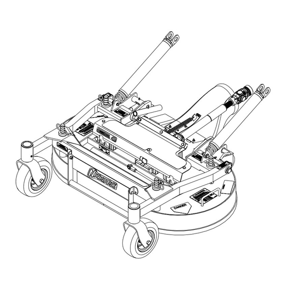
Stop engine, wait for all moving parts to stop and remove key. Roll the mower deck up to the Navigator tractor with the discharge tube down, making sure the deck springs are located above the drive wheel and below the console on each side. CD42CD; CD48CD 42” Deck 48” Deck 43.2”... - Page 10 Raise seat and install drive shaft onto jackshaft (See Figure 2). JACKSHAFT AND DRIVE SHAFT CONNECTION Align deck push arm tubes to tractor push arms and push deck rearward. Secure push arms with lynch pins on left and right sides of the unit. See Figure 3. PUSH ARM INSTALLATION Align upper portion of the PTO rubber guard to the tabs on the front of the console and secure with a clevis pin and hairpin on each side.
-
Page 11: Deck Removal
Un-latch deck from raised position, slowly lower deck to ground and lock deck locking pins on each side per section 4.1.2, Lowering the Deck to the Operation Position. 3.4 DECK REMOVAL Stop engine, wait for all moving parts to stop, and remove key. Raise mower deck up and latch with deck locking pins per section 4.1.1, Raising the Mower Deck to the Service Position. -
Page 12: Deck Raising And Lowering
4.1 DECK RAISING AND LOWERING 4.1.1 Raising the Mower Deck into Service Position: a) Stop engine, wait for all moving parts to stop and remove key. POTENTIAL HAZARD ♦ Incorrectly raising or lowering a mower deck can be dangerous. WHAT CAN HAPPEN ♦... -
Page 13: Maintenance
Push deck locking pins inward and rotate forward to securely lock deck in lowered position. See Figure 6. POTENTIAL HAZARD ♦ Operating mower without locking pins securely latched can result in the mower deck folding up unexpectedly. WHAT CAN HAPPEN ♦... - Page 14 POTENTIAL HAZARD ♦ Operating a mower deck with loose or weakened blade bolts can be dangerous. WHAT CAN HAPPEN ♦ A loose or weakened blade bolt could allow a blade rotating at a high speed to come out from under the deck, causing serious injury or property damage.
- Page 15 Pack the bearings with a NGLI grade #1 multi-purpose grease. Insert (1) bearing, (1) new seal into the wheel. NOTE: Seals (Exmark PN 103-0063) must be replaced. If the axle assembly has had both spacer nuts removed (or broken loose), apply a thread locking adhesive to (1) spacer nut and thread onto the axle with the wrench flats facing outward.
-
Page 16: Adjustments
Re-install the seal guards over the wheel hub and insert wheel into caster fork. Re-install caster bolt and tighten nut fully. IMPORTANT: To prevent seal and bearing damage, check the bearing adjustment often. Spin the caster tire. The tire should not spin freely (more than 1 or 2 revolutions) or have any side play. - Page 17 4.3.2 Deck Leveling: Position mower on a flat surface. Stop engine, wait for all moving parts to stop, and remove key. Inflate drive tires to 15 psi (103 kPa). Verify all hairpins are in the 3” deck height holes with the spacers under the hair pins.
-
Page 18: Parts List
322-3 Screw, HH 5/16-18 x 3/4 ...7 Exmark red touch up paint (spray paint - P/N 1-850337 - .6 oz liquid bottle - P/N 103-9140). Use Pro-Lock, Nut Type (P/N 1-840022, .5ml tube) on setscrew, item #45. Deck assembly includes anti skid pad, item #66. - Page 19 5.1 DECK GROUP...
-
Page 20: Front Frame Group
103-8630 Pad, Anti Skid (48”)...1 Exmark red touch up paint (spray paint - P/N 1-850337 - .6 oz liquid bottle - P/N 103-9140). Includes frame weldment plus items #7, #13, #14, #19, #21, #25, #37, #38, and Decals. Include zerk, item #30. -
Page 21: Front Frame Group
5.2 FRONT FRAME GROUP... -
Page 22: Gearbox Components
Output Cap W/Race...2 109-0197 Asm, Connector Tube 42” Short...1 Exmark red touch up paint (spray paint - P/N 1-850337 - .6 oz liquid bottle - P/N 103-9140). Includes o-rings, item #11 Includes (1) output seal assembly, item #9 Apply bead of Mobil HTS grease (P/N 103-5217 1.5 oz packet) between seal, item #10 and v-ring, item #13. -
Page 23: Warranty
Company, pursuant to an agreement between them, jointly warrant on the terms and conditions herein, that we will repair, replace or adjust any part manufactured by Exmark and found by us (in the exercise of our reasonable discretion) to be defective in factory materials or workmanship for a period of two years. - Page 24 SEE EXMARK’S COMPLETE CUSTOM RIDE SEAT SUSPENSION SYSTEM ROLL OVER PROTECTION SYSTEM (ROPS) ULTRA VAC COLLECTION SYSTEM ULTRA VAC QUICK DISPOSAL SYSTEM © 2005 EXMARK MFG. CO. INC. INDUSTRIAL PARK BOX 808 BEATRICE, NE 68310 ALL RIGHTS RESERVED LINE OF ACCESSORIES...