Table of Contents
Advertisement
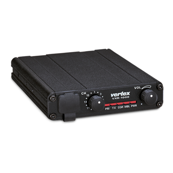
Vehicular
Cross-band Repeater
VXR-1000
Service Manual
©2009 VERTEX STANDARD CO., LTD. Printed in Japan.
The VXR-1000 Series is designed to provide extended handheld coverage by repeating transmissions
in both directions through an existing high power mobile radio.
Reliability is assured by a highly integrated surface mount circuit design and a aluminum extrusion
chassis. Important channel frequency data is stored in EEPROM, and is easily programmable by
dealers using a personal computer and the Vertex VPL-1 Programming Cable and CE-22 Software.
Please take a few minutes to read this manual carefully. The information presented here will allow
you to derive maximum performance from your VXR-1000. After reading it, keep the manual handy
for quick reference, in case questions arise later on.
We're glad you joined the VERTEX STANDARD team. Call on us any time, because our business is
communications. Let us help you get your message across.
Operating Manual Reprint ........................ 2
Specifications ............................................... 4
Installations .................................................. 5
Vertex VX- Series Transceiver ........ 7
VXR-1000 Trunking Interface Manual ....... 11
CE-22 Programming Software .................. 14
(UHF)
E133790B
Contents
VERTEX STANDARD CO., LTD.
4-8-8 Nakameguro, Meguro-Ku, Tokyo 153-8644, Japan
VERTEX STANDARD
US Headquarters
10900 Walker Street, Cypress, CA 90630, U.S.A.
YAESU UK LTD.
Unit 12, Sun Valley Business Park, Winnall Close
Winchester, Hampshire, SO23 0LB, U.K.
VERTEX STANDARD HK LTD.
Unit 5, 20/F., Seaview Centre, 139-141 Hoi Bun Road,
Kwun Tong, Kowloon, Hong Kong
VERTEX STANDARD ( AUSTRALIA ) PTY., LTD.
Normanby Business Park, Unit 14/45 Normanby Road
Notting Hill 3168, Victoria, Australia
Exploded View & Miscellaneous Parts ........ 25
Block Diagram .............................................. 26
Circuit Description ...................................... 27
Alignment ...................................................... 29
Repeater Cloning.......................................... 32
Board Unit (Schematics, Layouts & Parts)
Main Unit ............................................................... 33
1
Advertisement
Table of Contents

Related Manuals for Vertex Standard VXR-1000 (UHF)


Summary of Contents for Vertex Standard VXR-1000 (UHF)
-
Page 1: Table Of Contents
VXR-1000. After reading it, keep the manual handy for quick reference, in case questions arise later on. We’re glad you joined the VERTEX STANDARD team. Call on us any time, because our business is communications. Let us help you get your message across. -
Page 2: Operating Manual Reprint
Operating Manual Reprint & C ONTROLS ONNECTORS Front Panel Rear Panel Microphone Jack EXT SP (External Speaker) Connect the microphone plug to this jack. An external loudspeaker may be connected to this 2-contact, 3.5-mm mini-phone jack. CHANNEL Selector Knob DSUB 9-Pin Accessory Connector This knob selects the operating channel. - Page 3 Operating Manual Reprint ARDWARE ETTINGS RUNKING PERATION JP1004: Controls the output impedance of the When the radio is connected to a trunking mo- transmit audio line to the mobile radio. bile you wish to access the system from your Short: low-Z (600 Ω); open: high-Z (4.7 handheld radio, key the handheld briefly then kΩ) * release the PTT key.
-
Page 4: Specifications
Specifications GENERAL Frequency Range: 450 - 470 MHz Number of Channels: 16 Channels Channel Spacing: 12.5/25 kHz Supply Voltage: 13.8V DC, negative ground −30 °C to +60 °C Ambient Temperature Range: Frequency Stability: ±2.5 ppm 50 Ω RF Input-Output Impedance: 8 Ω... -
Page 5: Installations
Installations VXR-1000 Connections The VXR-1000 must only be installed in vehi- cles having a negative ground electrical system. The VXR-1000 provides a convenient rear-pan- Mount the transceiver where the Indicators, con- el Accessory Connector for easy connections to trols, and microphone are easily accessible, us- your transceiver. - Page 6 Installations VXR-1000 Connections Input impedance: 100 kΩ The input level can be changed via CE-22 (range) and Ž Œ VR1002 (value). CE-22 EXT MOD level “HIGH”: –18 dBm ~ –2 dBm CE-22 EXT MOD level “LOW”: –36 dBm ~ –18 dBm Frequency response (de-emphasis on/off) can be changed via CE-22 (default: off).
-
Page 7: Interconnection With Vertex Vx- Series Transceiver
Interconnection with Vertex VX- Series Transceivers This document outlines the interconnections and hardware settings required for interface of the Ver- tex VXR-1000 Compact Mobile Repeater to the Vertex VX- series of mobile transceivers. 1. Interconnections to Mobile Transceivers The chart below shows the interconnections between J1004 on the VXR-1000 and the correspond- ing interface jacks on the compatible mobile transceivers. - Page 8 Interconnection with Vertex VX- Series Transceivers 2. FTL-7011 3-3: CE-22 “Common Data” (F2) Settings VXR-1000) ARDWARE OFTWARE ETTINGS FOR Use the “CE22 /P” option when starting the CE-22 Software. 2-1: VXR-1000 Internal Jumpers PTT1 State: High : JP1001 Open OWER UPPLY ONTROL PTT2 State: High...
- Page 9 Interconnection with Vertex VX- Series Transceivers 1000) for an output deviation of ±3.0 kHz OMMON (±1.5 kHz in the “Narrow” mode). ISCELLANEOUS PTT] XTERNAL 5-2: VXR-1000 Receiver Output Level Setting Set to (Mic & Option) When the VXR-1000 receives a signal from an external signal source (on the uplink fre- ROUP quency used by the portable transceiver)
- Page 10 Interconnection with Vertex VX- Series Transceivers VX-3000U VX-3000L If JP1002 is not jumpered, connect this If JP1016 is not jumpered, connect this line to Pin 8 of Q1043. line to Pin 8 of Q1043. If JP1002 is jumpered, connect the If JP1016 is jumpered, connect the Mobile COR Detect line to JP1002.
-
Page 11: Vxr-1000 Trunking Interface Manual
VXR-1000 Trunking Interface Manual This document outlines the interconnections and 2-1-2: VXR-1000 Interconnections to FTL-7011 hardware settings required for interface of the VXR-1000 DSUP 9-pin FTL-7011 Vertex VXR-1000 Compact Mobile Repeater to Accessory Connector the Vertex VX- series of mobile transceivers in a Pin 1: GND Pin 8 of J2006 trunked environment (using the Vertex VX-... - Page 12 VXR-1000 Trunking Interface Manual 4. VX-TRUNK S 2-3: Interconnections to VX-3000/Configuration YSTEM PERATING 2-3-1: VXR-1000 Internal Jumpers XAMPLE *JP1004 Open 4-1: Making a Call from the Portable *JP1005 Jumpered 1. Press the portable's PTT key for longer than 2-3-2: VX-3000 Internal Jumpers the "Sampling Time"...
- Page 13 VXR-1000 Trunking Interface Manual 5. N interruption, but the incoming message from OTES RUNKING PERATION the VXR-1000 to the portable may sound 5-1: "choppy" due to the frequent interrupts. The VX-Trunk II system operates in a full du- When the portable transmits longer than the plex mode.
-
Page 14: Programming Software
CE-22 Program Software The Vertex CE-22 program is a software package which controls the VXR-1000's "Clone Edit" feature. This manual outlines the installation and use of the CE-22 software when used with the VXR-1000. 1. CE-22 Installation The CE-22 program will now start. After five seconds in an initial Program Identification and Operating Modes screen, the software will automatically... - Page 15 CE-22 Program Software py diskette, by use of the F4 command. You A channel number on which data has been will be prompted to define a file name to be hidden will display "-- --" in place of the field used.
- Page 16 CE-22 Program Software "active" status (except for CHANNEL 1, played, press [ENTER] to accept this value. which cannot be hidden). If you keyed in an invalid frequency (not among the "standard" CTCSS tone list), the Hidden channels will show "-- --" in place TONE SELECT window will appear, with of the various field entries, and they are not the nearest valid CTCSS frequency pre-se-...
- Page 17 CE-22 Program Software among the "standard" CTCSS tone list), the portable radio's ARTS Mode must be in TONE SELECT window will appear, with complement in order for ARTS to function the nearest valid CTCSS frequency pre-se- correctly. lected. 6-1: ARTS Mode Turning CTCSS ON turns DCS OFF (since ARTS operates in one of four modes, de- both cannot be ON).
- Page 18 CE-22 Program Software 7-2: DDec Type (DCS Decoder Type) Press the SPACE bar to select the desired This command selects the manner in which channel spacing environment. DCS is to be decoded. 11. Input Modulation Fixed = Decodes the type selected in 7-1 11-1: Mod In (Input Modulation Selection) only (Normal or Inverted).
- Page 19 CE-22 Program Software 14. Trunking Operation mit in tandem with the mobile radio when the mobile microphone's PTT switch is 14-1: Trunking pressed. If this command is set to OFF, the This command activates or de-activates the VXR-1000 will not transmit when the mo- intercommunication protocol for Trunking bile microphone's PTT switch is pressed.
- Page 20 CE-22 Program Software 18. External Radio Control Press the Space bar to select the desired Master Tone. 18-1: EXT.R Cntl This command selects the manner in which Note: If the Master/Slave Mode setting is not the VXR-1000 will control (and be controlled set to LkTn, the Master Tone command will by) the connected mobile radio.
- Page 21 CE-22 Program Software Note: If the Yaesu system is used, you must High: If the connected mobile radio uses an program only CTCSS or Carrier Squelch to "Active High" system, set the PTT1 be used for the main coded squelch signal State parameter to High.
- Page 22 CE-22 Program Software emphasis network, please set this parame- 21-7: Band ter to On. This parameter must be set for the band on which the VXR-1000 is transmitting. 21-4: De-Emphasis The audio signal received by the connected 21-8: COM Port mobile (received from the base station) is Set this parameter for the COM port you will applied to the VXR-1000 via Pin 6 of J1004.
- Page 23 CE-22 Program Software This parameter sets the number of times that ing service work, etc., or to check a VXR- a connection attempt will be made by the 1000's data for possible programming er- mobile radio, after which the trunking con- rors.
- Page 24 CE-22 Program Software This optional causes you to exit the [F2] for archive purposes. (Common) window and return to the Chan- [F8] Ch Edit nel Editing screen. This optional causes you to exit the [F3] B-2: Sub-Functions within [F3] (Disk Load) and (Disk Load) or [F4] (Disk Save) window and [F4] (Disk Save) return to the Channel Editing screen.
-
Page 25: Exploded View & Miscellaneous Parts
Exploded View & Miscellaneous Parts VXSTD P/N Description Qty. Accessories SEMS SCREW HSM 2.6× × × × × 4 U04204001 Description VXSTD P/N Qty. TAPTITE SCREW M3× × × × × 6B U24306007 CT CABLE T9101496A BINDING HEAD SCREW M2.6× × × × × 6 U20206001 FOOT S4000046... -
Page 26: Block Diagram
Block Diagram... -
Page 27: Circuit Description
Circuit Description Reception and transmission are switched by ing through a limiter amplifier, the signal is de- "RX5V" and "TX5V" lines from the microproces- modulated by the FM detector. sor unit (MPU). The receiver uses double-conver- Demodulated receive audio from the IF-IC is sion superheterodyne circuitry, with a 44.3 MHz amplified by Q1005 (NJM2902M). - Page 28 Circuit Description DCS Demodulator MHz), the temperature compensation circuit which includes D2007 (1SS353) and thermostats DCS signals are demodulated on the RF-UNIT, TH2001 and TH2002, and the transmit (DCS) and are applied to low-pass filter in sections 3 modulation circuit D2005/ D2006 (HVU350 × 2). and 4 of Q1040 (NJM2902M), as well as the lim- iter comparator in section 1 of Q1040.
-
Page 29: Alignment
All compo- 50-Ω RF Signal Dummy Load Generator nent replacement and service should be per- formed only by an authorized Vertex Standard RF Sampling representative, or the warranty policy may be Inline Wattmeter Coupler VXR-1000 voided. - Page 30 Alignment Ë Release the PTT switch, then turn the VXR- Transmitter Output Power 1000 off. PC Alignment Ë Select channel 3, transmit, and adjust the out- CTCSS Modulation Level put power level for 5.0 watts using the PC. Ë Select channel #4, with 151.4 Hz CTCSS en- Manual Alignment code.
- Page 31 Alignment Squelch Threshold I Squelch Threshold II You can now adjust the Squelch Threshold for PC Alignment each channel. Ë Select channel #2, and adjust the signal gen- erator level for 0 dBµ (1.0 µV). Ë Turn the VXR-1000 off. Ë...
-
Page 32: Repeater Cloning
Repeater Cloning You can transfer data stored in one VXR-1000 to another VXR-1000 by utilizing the handy “Cloning” feature. This requires the optional T9101411 Cable and FRB-4 Alignment Interface Box, so as to connect the Microphone jacks on the two repeaters as shown below. To clone from one repeater to another, use the following procedure: Ë... -
Page 33: Main Unit
Main Unit (Lot. 1~) Circuit Diagram 5.0V(0.2V) 2.2V 10.5V 5.0V 0.2V(5.0V) 12.6V 2.2V 13.8V 2.2V 5.0V(4.3V) 2.2V 13.8V 2.2V 9.0V 13.7V 5.0V 4.3V(5.0V) 13.2V 13.1V 5.0V 0V(5.0V) 5.0V 2.9V(0V) 0V(5.0V) 0.7V 5.0V 3.7V 3.7V 3.7V 3.2V 5.0V 3.7V LED ON: 3.0V LED OFF: 5.0V 4.9V LED ON: 0V... - Page 34 Main Unit (Lot. 1~) 4.4V 3.7V (0.8V) 0.7V 0.6V 0.7V 4.4V 0.7V 0.3V 4.3V 5.0V (0.7V) (4.7V) (1.7V) 0.6V 1.8V 0.6V 0.7V 1.1V (4.3V) 3.4V (4.9V) 3.7V 4.4V 4.4V 12.6V 3.7V 3.8V 4.8V 2.9V 1.4V 4.5V 3.7V 2.3V 0.7V 1.6V 0.8V 5.0V 3.7V...
- Page 35 Main Unit (Lot. 1~) Parts Layout MC145191FR M67799HA (Q2009) (Q2003) HD64F3334YTF16 (Q1039) MX165CDW MC14053BFR MC3372ML (Q1016) (Q1019) (Q2013) NJM2902M BR93LC66RF (Q1005, 1037, 1040) (Q1051) LA4425A (Q1003) 2SD1667R µPC2710T (C1F) IMH11 (H11) (Q1010) (Q2015) (Q1028, 1032, 1036) 2SJ125D (JD) DTC114EK (24) 2SC3356 (R25) (Q1058) (Q1056, 1057, 1060)
- Page 36 Main Unit (Lot. 1~) M64026FP µPD74HC4066G L78M05T (Q1059) (Q1001) (Q1023) NJM2902M (Q1002, 1006) TA75S01F (SA) RH5VL45AA (D5) NJM78L09UA (8H) (Q2018) (Q1022) (Q1055) 2SD1767Q (DC) (Q2002) SGM2016AM (M-) IMH11 (H11) (Q2004) (Q1009, 1027, 1053, 1054) DTC114EK (24) 2SD1368CB (CB) 2SB1132R (BA) (Q1004, 1007, 1012, (Q1017) (Q1015, 1033, 1034)
- Page 37 Main Unit (Lot. 3~) Circuit Diagram...
- Page 38 Main Unit (Lot. 3~)
- Page 39 Main Unit (Lot. 3~) Parts Layout MC145191FR M67799HA (Q2009) (Q2003) HD64F3334YTF16 (Q1039) MX165CDW MC14053BFR MC3372ML (Q1016) (Q1019) (Q2013) NJM2902M BR93LC66RF (Q1005, 1037, 1040) (Q1051) LA4425A (Q1003) 2SD1667R µPC2710T (C1F) IMH11 (H11) (Q1010) (Q2015) (Q1028, 1032, 1036) 2SJ125D (JD) DTC114EK (24) 2SC3356 (R25) (Q1058) (Q1056, 1057, 1060)
- Page 40 Main Unit (Lot. 3~) M64026FP µPD74HC4066G L78M05T (Q1059) (Q1001) (Q1023) NJM2902M (Q1002, 1006) TA75S01F (SA) RH5VL45AA (D5) NJM78L09UA (8H) (Q2018) (Q1022) (Q1055) 2SD1767Q (DC) (Q2002) SGM2016AM (M-) IMH11 (H11) (Q2004) (Q1009, 1027, 1053, 1054) DTC114EK (24) 2SD1368CB (CB) 2SB1132R (BA) (Q1004, 1007, 1012, (Q1017) (Q1015, 1033, 1034)
-
Page 41: Parts List
MAIN Unit Parts List LAY ADR REF. DESCRIPTION VALUE TOL. MFR’S DESIG VXSTD P/N VERS. LOT. SIDE *** MAIN UNIT *** PCB with Components (w/ Q1010 2SD1667R) CS1625001 Printed Circuit Board FR002830B Printed Circuit Board FR002830C C 1001 CHIP CAP. 0.1uF GRM21BB11E104KA01L K22140811... - Page 42 MAIN Unit REF. DESCRIPTION VALUE TOL. MFR’S DESIG VXSTD P/N VERS. LOT. SIDE LAY ADR C 1055 CHIP CAP. 470pF GRM216B11H471KA01D K22170801 C 1056 CHIP CAP. 47pF GRM2162C1H470JZ01D K22170227 C 1057 CHIP CAP. 100pF GRM2162C1H101JA01D K22170235 C 1058 CHIP CAP. 0.0047uF GRM216B11H472KA01D K22170813...
- Page 43 MAIN Unit REF. DESCRIPTION VALUE TOL. MFR’S DESIG VXSTD P/N VERS. LOT. SIDE LAY ADR C 1118 CHIP CAP. 0.1uF GRM21BB11E104KA01L K22140811 C 1119 CHIP CAP. 0.001uF GRM216B11H102KA01D K22170805 C 1120 CHIP CAP. 0.001uF GRM216B11H102KA01D K22170805 C 1121 CHIP CAP. 0.1uF GRM21BB11E104KA01L K22140811...
- Page 44 MAIN Unit REF. DESCRIPTION VALUE TOL. MFR’S DESIG VXSTD P/N VERS. LOT. SIDE LAY ADR C 2063 CHIP CAP. 0.001uF GRM216B11H102KA01D K22170805 C 2064 CHIP CAP. 0.1uF GRM21BB11E104KA01L K22140811 C 2065 CHIP CAP. 100pF GRM2162C1H101JA01D K22170235 C 2066 CHIP CAP. 33pF GRM2162C1H330JZ01D K22170223...
- Page 45 MAIN Unit REF. DESCRIPTION VALUE TOL. MFR’S DESIG VXSTD P/N VERS. LOT. SIDE LAY ADR C 2131 CHIP CAP. 220pF GRM2162C1H221JZ01D K22170243 C 2132 CHIP CAP. 220pF GRM2162C1H221JZ01D K22170243 C 2133 CHIP CAP. 0.047uF GRM21BB11H473KA01L K22170823 C 2134 CHIP CAP. 0.047uF GRM21BB11H473KA01L K22170823...
- Page 46 Q 1060 TRANSISTOR DTC114EK T146 G3070002 Q 1061 TRANSISTOR DTC114EK T146 G3070002 Q 2001 TRANSISTOR 2SC3356-T2B R25 G3333567E Q 2002 TRANSISTOR 2SD1767 T100 Q G3417677Q Q 2003 IC M67799HA-01 G1092847 Q 2003 IC M67799HA-01 G1092847 : Please contact Vertex Standard...
- Page 47 MAIN Unit REF. DESCRIPTION VALUE TOL. MFR’S DESIG VXSTD P/N VERS. LOT. SIDE LAY ADR Q 2003 IC M67799HA-23 G1092882 Q 2003 IC RA07H4452M-101 G1094331 Q 2004 FET SGM2016AM-T7 G4070012 Q 2006 TRANSISTOR 2SC2812L6-TA G3328127F Q 2008 TRANSISTOR 2SC3356-T2B R25 G3333567E Q 2009 IC MC145191FR2...
- Page 48 MAIN Unit REF. DESCRIPTION VALUE TOL. MFR’S DESIG VXSTD P/N VERS. LOT. SIDE LAY ADR R 1046 CHIP RES. 4.7k 1/10W RMC1/10T 472J J24205472 R 1047 CHIP RES. 4.7k 1/10W RMC1/10T 472J J24205472 R 1048 CHIP RES. 1/4W RMC1/4 221JATP J24245221 R 1049 CHIP RES.
- Page 49 MAIN Unit REF. DESCRIPTION VALUE TOL. MFR’S DESIG VXSTD P/N VERS. LOT. SIDE LAY ADR R 1108 CHIP RES. 1/10W RMC1/10T 103J J24205103 R 1109 CHIP RES. 150k 1/10W RMC1/10T 154J J24205154 R 1110 CHIP RES. 150k 1/10W RMC1/10T 154J J24205154 R 1111 CHIP RES.
- Page 50 MAIN Unit REF. DESCRIPTION VALUE TOL. MFR’S DESIG VXSTD P/N VERS. LOT. SIDE LAY ADR R 1174 CHIP RES. 1/16W RMC1/16 105JATP J24185105 R 2002 CHIP RES. 100k 1/10W RMC1/10T 104J J24205104 R 2003 CHIP RES. 4.7k 1/10W RMC1/10T 472J J24205472 R 2004 CHIP RES.
- Page 51 MAIN Unit REF. DESCRIPTION VALUE TOL. MFR’S DESIG VXSTD P/N VERS. LOT. SIDE LAY ADR R 2069 CHIP RES. 1/10W RMC1/10T 105J J24205105 R 2070 CHIP RES. 1/10W RMC1/10T 220J J24205220 R 2071 CHIP RES. 1/10W RMC1/10T 000J J24205000 R 2072 CHIP RES.
- Page 52 REF. DESCRIPTION VALUE TOL. MFR’S DESIG VXSTD P/N VERS. LOT. SIDE LAY ADR *** MAIN ASSY *** C 0001 CERAMIC CAP. 8.2pF UP050SL8R2K-A-B K28179024 J 0001 CONNECTOR BNC-R (050-1400) P1090376...
- Page 54 No portion of this manual may be reproduced without Copyright 2009 the permission of VERTEX STANDARD CO., LTD. VERTEX STANDARD CO., LTD. All rights reserved Printed in Japan.