Table of Contents
Advertisement
Quick Links
Advertisement
Table of Contents
Troubleshooting

Related Manuals for Mitsubishi Melsec-A AJ65SBT


Summary of Contents for Mitsubishi Melsec-A AJ65SBT
-
Page 3: Safety Precautions
• • SAFETY PRECAUTIONS (Be sure to read these instructions before using the product.) Before using this product, read this manual and the relevant manuals introduced in this manual carefully and handle the product correctly with full attention to safety. The precautions given in this manual are concerned with this product. -
Page 4: Wiring Precautions
[Installation Precautions] CAUTION • Use each product in an environment as specified in the "general specification" in this manual. Using the programmable controller outside the range of the general specifications may result in electric shock, fire or malfunction, or may damage or degrade the product. •... - Page 5 [Wiring Precautions] CAUTION • Always secure the communication cable connected to the product by running it in a conduit or clamping it. Not doing so can cause damage to the product and/or cable due to the dangling, motion, careless pulling, etc. of the cable or cause a malfunction due to a faulty connection of the cable. •...
-
Page 6: Revisions
This manual confers no industrial property rights or any rights of any other kind, nor does it confer any patent licenses. Mitsubishi Electric Corporation cannot be held responsible for any problems involving industrial property rights which may occur as a result of using the contents noted in this manual. -
Page 7: Table Of Contents
INTRODUCTION Thank you for purchasing the MELSEC-A series programmable controller. Before using the product, read this manual carefully to fully understand the functions and the performance of the programmable controller. Please forward a copy of this manual to the end user. CONTENTS SAFETY PRECAUTIONS..........................A- 1 REVISIONS ..............................A- 4... - Page 8 3.7.2 Last station number setting (common to 2, 4 and 8 occupied stations (4 occupied stations 2 modules): Address RWwn) ......................3-20 3.7.3 Data link stop/restart instructions (common to 2, 4 and 8 occupied stations (4 occupied stations 2 modules): Address RWwn+1)......................3-20 3.7.4 Error status flag clear (common to 2, 4 and 8 occupied stations (4 occupied stations 2 modules): Address RWwn+2)......................
- Page 9 6. TROUBLESHOOTING 6- 1 to 6-19 6.1 Station Status at Error Occurrence ......................6- 1 6.2 Troubleshooting Flow..........................6- 2 6.3 Troubleshooting when the "ERR" LED on the Master Station is Flashing..........6- 3 6.4 Troubleshooting when the "PW" LED of the AJ65SBT-CLB has Turned Off ........6- 5 6.5 CC-Link Side Troubleshooting.........................
-
Page 10: Manuals
(1) For programmable controller system To configure a system meeting the requirements of the EMC and Low Voltage Directives when incorporating the Mitsubishi programmable controller (EMC and Low Voltage Directives compliant) into other machinery or equipment, refer to the "EMC AND LOW VOLTAGE DIRECTIVES" chapter of the User's Manual for the CPU module used. -
Page 11: Generic Terms And Abbreviations
Generic Terms and Abbreviations Unless otherwise specified, this manual uses the following generic terms and abbreviations. Generic Term/Abbreviation Description AJ65SBT-CLB Abbreviation for AJ65SBT-CLB CC-Link - CC-Link/LT bridge module. Generic product name for the product types SWnD5C-GPPW-E, SWnD5C-GPPW-EA, GX Developer SWnD5C-GPPW-EV and SWnD5C-GPPW-EVA. (n indicates any of Versions 0 to 7) Station that controls data link system. -
Page 12: Overview
1 OVERVIEW MELSEC-A 1 OVERVIEW This manual provides the specifications, part names, setting, etc. of the AJ65SBT-CLB CC-Link - CC-Link/LT bridge module (hereafter referred to as the AJ65SBT-CLB) that is designated to be used as a remote device station in a CC-Link system. 1.1 Overview The AJ65SBT-CLB includes the bridge function to establish a connection between CC- Link and CC-Link/LT. -
Page 13: Features
1 OVERVIEW MELSEC-A 1.2 Features The AJ65SBT-CLB has the following features. (1) Seamless connection of two networks The AJ65SBT-CLB is a bridge module that can connect CC-Link and CC-Link/LT seamlessly. Using RX and RY (bit devices), one bridge module can control up to 224 points (448 points when both inputs and outputs are used). -
Page 14: System Configuration
2 SYSTEM CONFIGURATION MELSEC-A 2 SYSTEM CONFIGURATION 2.1 Overall Configuration This section explains a system including the AJ65SBT-CLB. For the transmission specifications, station-to-station distance, overall cable distance (maximum transmission distance), etc. of CC-Link, refer to the user's manual of the master module. -
Page 15: Applicable System
2 SYSTEM CONFIGURATION MELSEC-A POINT (1) The connection order of remote stations is not relevant to the station numbers. (2) The remote station numbers are not necessarily consecutive. (Empty station number does not cause data link failure.) 2.2 Applicable System This section explains the applicable master modules and the precautions for system configuration. -
Page 16: Precautions For System Configuration
2 SYSTEM CONFIGURATION MELSEC-A 2.3 Precautions for System Configuration (1) Arrangement of AJ65SBT-CLB (a) CC-Link side The AJ65SBT-CLB can be placed in any position as the remote device station of the CC-Link system. (b) CC-Link/LT side Since T-branch connection can be made, the AJ65SBT-CLB can apparently be placed midway through the trunk line. - Page 17 2 SYSTEM CONFIGURATION MELSEC-A (3) Mounting condition for CC-Link/LT dedicated power supply or power supply adaptor The mounting conditions for a dedicated power supply or power supply adapter for the CC-Link/LT vary depending on the devices to be connected and the wiring length.
- Page 18 2 SYSTEM CONFIGURATION MELSEC-A (b) Instantaneous power failure of remote I/O module When instantaneous power failure occurs in the power source (24V DC) for the remote I/O module, incorrect data may be input. 1) Causes of incorrect input due to instantaneous power failure The hardware of the remote I/O module converts the supplied power of 24V DC into 5V DC inside the module and uses it for its own operation.
- Page 19 2 SYSTEM CONFIGURATION MELSEC-A 2) Preventive measure against incorrect input Install wiring so that the power is supplied from the same power source to the power supply module, stabilized power supply and external power supply for AC input. Remote I/O module AJ65SBT-CLB DC input Power supply...
-
Page 20: Parts Sold Separately
(110Ω) (including 1) 1 Mitsubishi's A6CON- 5P includes 10 plugs. 2 Once insulation-displaced, the one-touch connector plugs cannot be reused. 3 Mitsubishi's A6CON- J5P includes 5 plugs. REMARK • As following table indicates, the optional plugs/connectors are compatible with the connectors for this module. - Page 21 2 SYSTEM CONFIGURATION MELSEC-A MEMO 2 - 8 2 - 8...
-
Page 22: Specifications
3 SPECIFICATIONS MELSEC-A 3 SPECIFICATIONS This chapter provides the specifications of the AJ65SBT-CLB. 3.1 General Specifications Table 3.1 General specifications Item Specifications Operating ambient 0 to 55°C temperature Storage ambient -25 to 75°C temperature Operating ambient 5 to 95%RH, non-condensing humidity Storage ambient 5 to 95%RH, non-condensing... -
Page 23: Performance Specifications
3 SPECIFICATIONS MELSEC-A 3.2 Performance Specifications The following table provides the performance specifications of the AJ65SBT-CLB. 3.2 Performance specifications Table Item Specifications Station type Remote device station CC-Link Version Ver.1.10 64 points each for RX and RY (16 points are used in the system) 2 stations 8 points each for RWr and RWw Number of... -
Page 24: Network Wiring Specifications
3 SPECIFICATIONS MELSEC-A Table 3.3 VCTF cable specifications (Extract from JIS C 3306) Conductor Conductor Insulator Sheath Type No. of cores Nominal cross- Composition Outside resistance thickness thickness sectional area No. of wires/wire diameter diameter Vinyl cabtyre, 25.1 0.75mm 30/0.18mm 1.1mm 0.6mm 1.0mm... - Page 25 3 SPECIFICATIONS MELSEC-A POINT When connecting multiple lines with dedicated connectors to form one trunk line, the number of connections must be 10 or less. Line connection Master station Remote Remote Terminating Power Terminating station station supply resistor resistor adapter Remote Remote station...
-
Page 26: Concept Of Remote Input/Output
3 SPECIFICATIONS MELSEC-A 3.4 Concept of Remote Input/Output This section explains the I/O signals for the AJ65SBT-CLB module. Example: The following provides an example of setting the AJ65SBT-CLB to 2 occupied stations and 4-point mode. Master station Station 1 Station 2 Station 3 1 station 2 stations... -
Page 27: Remote I/O Signals For Cc-Link Master Module
3 SPECIFICATIONS MELSEC-A 3.5 Remote I/O Signals for CC-Link Master Module This section explains the I/O signals of the AJ65SBT-CLB for the CC-Link master module. 3.5.1 Remote I/O signal list when 2 stations are occupied Out of 64 points, 16 points are used as a system area. Signal Direction: AJ65SBT-CLB master module Signal Direction: Master module... -
Page 28: Remote I/O Signal List When 4 Stations Are Occupied
3 SPECIFICATIONS MELSEC-A 3.5.2 Remote I/O signal list when 4 stations are occupied Out of 128 points, 16 points are used as a system area. Signal Direction: AJ65SBT-CLB Master module Signal Direction: Master module AJ65SBT-CLB Remote input (RX) Name Remote output (RY) Name RXn0 RYn0... -
Page 29: Remote I/O Signal List When 8 Stations Are Occupied (4 Occupied Stations 2 Modules)
3 SPECIFICATIONS MELSEC-A 3.5.3 Remote I/O signal list when 8 stations are occupied (4 occupied stations 2 modules) Out of 256 points, 32 points are used as a system area. When 8 stations (4 occupied stations 2 modules) are occupied, two 4-station occupying modules are placed in series. -
Page 30: Details Of Remote I/O Signals
3 SPECIFICATIONS MELSEC-A 3.5.4 Details of remote I/O signals This section explains the assignment and functions of the CC/Link remote inputs/outputs. (1) Remote I/O signal list for 4-point mode setting (a) The following table lists the I/O signals for 2 occupied station setting Remote input (RX) of Remote input (X) of CC-Link/LT CC-Link... - Page 31 3 SPECIFICATIONS MELSEC-A (c) The following table lists the I/O signals for 8 occupied station (4 occupied stations 2 modules) setting Remote input (RX) of Remote input (X) of CC-Link/LT CC-Link RXnF to RXn0 Station number 4 Station number 3 Station number 2 Station number 1 RX(n 6)F to RX(n 6)0...
- Page 32 3 SPECIFICATIONS MELSEC-A (2) Remote I/O signal list for 8-point mode setting (a) The following table lists the I/O signals for 2 occupied station setting Remote input (RX) of Remote input (X) of CC-Link/LT CC-Link RXnF to RXn0 Station number 2 Station number 1 RX(n 2)F to RX(n 2)0 Station number 6...
- Page 33 3 SPECIFICATIONS MELSEC-A (c) The following table lists the I/O signals for 8 occupied station (4 occupied stations 2 modules) setting Remote input (RX) of Remote input (X) of CC-Link/LT CC-Link RXnF to RXn0 Station number 2 Station number 1 RX(n 6)F to RX(n 6)0 Station number 14 Station number 13...
- Page 34 3 SPECIFICATIONS MELSEC-A (3) Remote I/O signal list for 16-point mode setting (a) The following table lists the I/O signals for 2 occupied station setting Remote input (RX) of Remote input (X) of CC-Link/LT CC-Link RXnF to RXn0 Station number 1 RX(n 2)F to RX(n 2)0 Station number 3 RX(n 3)F to RX(n 3)0...
- Page 35 3 SPECIFICATIONS MELSEC-A (c) The following table lists the I/O signals for 8 occupied station (4 occupied stations 2 modules) setting Remote input (RX) of Remote input (X) of CC-Link/LT CC-Link RXnF RXn0 Station number 1 RX(n 6)F RX(n 6)0 Station number 7 RX(n 7)F RX(n 7)0 Use prohibited...
-
Page 36: Concept Of The Number Of Control Points (Point Mode Setting For Cc-Link/Lt And Number Of Occupied Stations Setting For Cc-Link)
3 SPECIFICATIONS MELSEC-A 3.6 Concept of the Number of Control Points (Point Mode Setting for CC-Link/LT and Number of Occupied Stations Setting for CC-Link) This section explains the concept of the settings required for system configuration, i.e., point mode setting and number of occupied stations setting. The point mode setting sets the number of points that can be controlled for each occupied remote station in the CC-Link/LT. - Page 37 3 SPECIFICATIONS MELSEC-A As the point mode, it is recommended to use the 4-point mode that has the least number of empty points. Example: In the case of one 2-point remote station, five 4-point remote stations, one 8-point remote station and one 16-point remote station Station 1 Station 2 Station 3...
- Page 38 3 SPECIFICATIONS MELSEC-A The assignment of the I/O numbers is explained below using the assignment sheet in the Appendices. It is an example where the number of occupied stations is 2 and the point mode setting is the 4-point mode as shown in the configuration of the Section (3).
-
Page 39: Remote Registers
3 SPECIFICATIONS MELSEC-A 3.7 Remote Registers The AJ65SBT-CLB has the remote registers to make data communication with the master module. This section explains the assignment and data structure of the remote registers of the AJ65SBT-CLB. 3.7.1 Assignment of remote registers The following tables indicate the assignment of the remote registers. - Page 40 3 SPECIFICATIONS MELSEC-A (c) When 8 stations (4 occupied stations 2 modules) are occupied First module Address Remote Register Definition Reference RWrn Data of operating statuses Sec. 3.7.5 RWrn 1 Data of faulty station : Station number 1 to 32 Sec.
-
Page 41: Last Station Number Setting
3 SPECIFICATIONS MELSEC-A 3.7.2 Last station number setting (common to 2, 4 and 8 occupied stations (4 occupied stations 2 modules): Address RWwn) The setting status of the last station number is stored. Name Description Initial value b0 to b7 Empty Fixed at 0 Set the last station number for a data link. -
Page 42: Data Of Operating Statuses
3 SPECIFICATIONS MELSEC-A 3.7.5 Data of operating statuses (common to 2, 4 and 8 occupied stations (4 occupied stations 2 modules): Address RWrn) The CC-Link/LT side operating status is stored. Name Description 0: Data link stopped Data link status 1: Data link being executed 0: Initial communication not completed Initial communication status 1: Initial communication completed... -
Page 43: Data Of Faulty Station
3 SPECIFICATIONS MELSEC-A 3.7.6 Data of faulty station (2 occupied stations: Address RWrn 1, common to 4 and 8 occupied stations (4 occupied stations 2 modules): Address RWrn 1, RWrn 2) The data link statuses of the CC-Link/LT remote stations are stored. •... -
Page 44: Remote I/O Error Data
3 SPECIFICATIONS MELSEC-A 3.7.7 Remote I/O error data (2 occupied stations: Address RWrn 2, common to 4 and 8 occupied stations (4 occupied stations 2 modules): Address RWrn 3, RWrn 4) The remote I/O error occurrence statuses of the CC-Link/LT remote stations during data link are stored. -
Page 45: Data Of Remote Station Connection
3 SPECIFICATIONS MELSEC-A 3.7.8 Data of remote station connection (2 occupied stations: Address RWrn 3, common to 4 and 8 occupied stations (4 occupied stations 2 modules): Address RWrn 5, RWrn 6) The CC-Link/LT remote stations connected on the line are detected, and the connection statuses of the remote stations are stored. -
Page 46: Setting Data
3 SPECIFICATIONS MELSEC-A 3.7.9 Setting data (2 occupied stations: Address RWrn+4, common to 4 and 8 occupied stations (4 occupied stations 2 modules): Address RWrn 7) The setting statuses of the switches for occupied station number setting, transmission speed setting, point mode setting, test mode and data link last station number are stored. -
Page 47: Data Link Processing Time
3 SPECIFICATIONS MELSEC-A 3.8 Data Link Processing Time The CC-Link side data link and CC-Link/LT side data link operate asynchronously. 3.8.1 CC-Link link scan time Refer to the user's manual of the master module. 3.8.2 CC-Link/LT link scan time This section explains the CC-Link/LT link scan time. [Link scan time (LS)] LS = a + (b c [ s]... -
Page 48: Transmission Delay Time
3 SPECIFICATIONS MELSEC-A 3.9 Transmission Delay Time Transmission delay time is indicated below. • For input Indicates the time from when a signal is input to the remote station until the device (X) of the CPU turns on (off). • For output Indicates the time from when the device (Y) of the CPU turns on (on) until the output of the remote station turns on (off). - Page 49 3 SPECIFICATIONS MELSEC-A MEMO 3 - 28 3 - 28...
-
Page 50: Procedure Up To Data Link
4 PROCEDURE UP TO DATA LINK MELSEC-A 4 PROCEDURE UP TO DATA LINK This chapter provides the procedure from AJ65SBT-CLB mounting to data link start. 4.1 Procedure Up to Data Link The following flowchart indicates the procedure to start the data link of the system using the AJ65SBT-CLB. - Page 51 4 PROCEDURE UP TO DATA LINK MELSEC-A Continued from the previous page Power on the CC-Link side. Start a data link on the CC-Link side. Make operation checks with the LEDs. (1) Check the CC-Link side operation. When data link is normal: L RUN turns on. When data link is abnormal: L ERR.
-
Page 52: Mounting And Installation
4 PROCEDURE UP TO DATA LINK MELSEC-A 4.2 Mounting and Installation 4.2.1 Handling precautions This section explains the precautions for handling the AJ65SBT-CLB. Do not touch the terminals while the module is energized. Doing so may cause CAUTION malfunctions. Be careful not to let foreign matter such as dust or wire chips get inside the module. This may cause a fire, failure or malfunctions. -
Page 53: Part Names And Settings
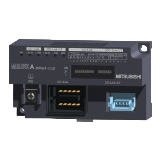
4 PROCEDURE UP TO DATA LINK MELSEC-A 4.3 Part Names and Settings This section explains the part names, LED displays, and setting methods of switch, etc for the AJ65SBT-CLB. Diagram 1 CC-Link CC-Link/LT CC-Link CC-Link/LT PW L ERR. LERR. ERR. STATION NO. - Page 54 4 PROCEDURE UP TO DATA LINK MELSEC-A Number Name Description Shows the module status as the LED on/off. LED name Description On: CC-Link side switch setting error <During normal operation> Data link communication fault error On: Data link error station (detected) Flicker: CC-Link side switch setting is Station outside control range changed during operation.
- Page 55 4 PROCEDURE UP TO DATA LINK MELSEC-A Diagram 1 CC-Link CC-Link/LT STATION NO. BRATE MODE BRATE 1 2 3 4 5 6 7 8 9 Case silkscreen No. : The case silkscreen No. corresponds to switch silkscreen No. 1 2 3 4 5 6 7 8 910 1 2 3 4 6 7 8 Switch silkscreen No.
-
Page 56: Facing Direction Of The Module Installation
4 PROCEDURE UP TO DATA LINK MELSEC-A Number Name Description Self-loopback test OFF: Normal operation mode (factory-set) setting switch ON: Self-loopback test mode (CC-Link/LT side) Setting Setting Switches Points Value Point mode setting switches (CC-Link/LT 8 points (factory-set) side) 4 points MODE 16 points Setting a value other than the above will result in a setting error. -
Page 57: Connecting Modules By Cc-Link/Lt Side Cables
4 PROCEDURE UP TO DATA LINK MELSEC-A 4.5 Connecting Modules by CC-Link/LT Side Cables This section explains the connection method using the cables designed for CC- Link/LT: The cables can be connected regardless of the order of the station number. Be sure to set the QJ61CL12 at the end of the trunk line. -
Page 58: How To Connect Dedicated Flat Cable Connector
4 PROCEDURE UP TO DATA LINK MELSEC-A 4.5.1 How to connect dedicated flat cable connector This section explains the connection method of the connector for the dedicated flat cable. (1) Components The components are as follows: Component 1: Cover Component 2: Body Component 3: Dedicated flat cable Orange 4 - 9... - Page 59 4 PROCEDURE UP TO DATA LINK MELSEC-A (2) Operating procedure The operating procedure is illustrated below. (a) Terminal Processing 1) Correctly place the dedicated flat cable 2) Close the cover so that the flat cable 3) Assemble the cover with the body and in the cover.
-
Page 60: How To Connect Vctf Or High Flexible Cable Connector
4 PROCEDURE UP TO DATA LINK MELSEC-A 4.5.2 How to connect VCTF or high flexible cable connector This section describes how to connect the VCTF cable connector or high flexible cable connector. (1) Components The components are shown below. Component 1: Cover Component 2: Body (Aqua) Component 3: VCTF cable/High flexible cable... - Page 61 4 PROCEDURE UP TO DATA LINK MELSEC-A (2) Operating steps The operating steps are shown below. (a) Processing Cable End 1) Place each wire of the VCTF cable 2) Close the cover so that the wires 3) Assemble the cover with the body or high flexible cable so that its wire are properly fitted.
- Page 62 4 PROCEDURE UP TO DATA LINK MELSEC-A 5)-2 When using a connector for T-branching After removing the sheath 7cm or more, make a T-branch wiring with a connector in the same way as the T-branch method for the dedicated flat cable. VCTF cable/High flexible cable (Trunk line) VCTF cable/ High flexible cable(Drop line)
-
Page 63: Mixture Of Different Kinds Of Cables
4 PROCEDURE UP TO DATA LINK MELSEC-A (3) Precautions for use of high flexible cables Wire the high flexible cable in a way to prevent from applying load to the high flexible cable connection even when the cable moves. 4.5.3 Mixture of different kinds of cables This section describes mixture of different kinds of cables. - Page 64 4 PROCEDURE UP TO DATA LINK MELSEC-A (3) System configuration example for using dedicated flat cable as trunk line AJ65SBT -CLB Remote Remote module module Remote Power supply 20cm or less adapter module Module Remote with cable module Remote Remote module module General...
- Page 65 4 PROCEDURE UP TO DATA LINK MELSEC-A (5) System configuration example for using high flexible cable as trunk line Connecting terminating resistor on AJ65SBT-CLB side Terminating resistor (CL9-TERM) Install AJ65SBT -CLB High flexible High flexible High flexible cable connector* cable connector cable (For AJ65SBT-CLB) (For terminating resistor)
-
Page 66: Mounting Terminating Resistors
4 PROCEDURE UP TO DATA LINK MELSEC-A 4.5.4 Mounting terminating resistors Use the CL9-TERM (Gray) for the terminating resistor. For the system configuration using the dedicated flat cables only, the CL9-RYVK (Black) can be also used. Note that the same type must be used for both ends of the trunk line. -
Page 67: Cc-Link Side Connection
4 PROCEDURE UP TO DATA LINK MELSEC-A 4.6 CC-Link Side Connection This section explains the wiring the CC-Link dedicated cables that connect the AJ65SBT-CLB and master module. 4 - 18 4 - 18... -
Page 68: Connection Of The Cc-Link Dedicated Cables
4 PROCEDURE UP TO DATA LINK MELSEC-A 4.6.1 Connection of the CC-Link dedicated cables Connect the CC-Link dedicated cable between the AJ65SBT-CLB and master module as shown below. One-touch connector plug Online connector for for communication communication One-touch connector plug with terminating resistor A6CON-TR11 [CC-Link dedicated cable wiring diagram]... -
Page 69: Wiring The One-Touch Connector Plug
4 PROCEDURE UP TO DATA LINK MELSEC-A 4.7 Wiring the One-Touch Connector Plug This section describes wiring the one-touch connector plug. Refer to section 2.4 for more information on the models and specifications of the one- touch connector plugs which comply to the AJ65SBT-CLB. Plug cover Plug body 1) Check the connector. - Page 70 4 PROCEDURE UP TO DATA LINK MELSEC-A (From the previous page) Pliers Latches 6) Press both ends of the plug cover After pressing the center part of the plug cover, press both ends of the plug cover where latches are located. Verify that the latches engage with the plug body.
-
Page 71: Wiring Check
4 PROCEDURE UP TO DATA LINK MELSEC-A 4.8 Wiring Check Check the wiring of the CC-Link/LT remote I/O stations and external devices. [Wiring check example] Master station X/Y0 to X/Y1F AJ65SBT-CLB Station No. 1, 2 occupied stations, 4-point mode CL2X8-D1B2 CL2Y8-TP1B2 Input module Output module... -
Page 72: Maintenance And Inspection
4 PROCEDURE UP TO DATA LINK MELSEC-A (2) When making refresh with FROM/TO instruction After network parameter setting, refresh RX/RY to X400/Y400 using the FROM/TO instruction. (a) Data link start The operation in this section is not required when the network parameters have been set using GX Developer or dedicated instruction. -
Page 73: Programming
5 PROGRAMMING MELSEC-A 5 PROGRAMMING This chapter explains the programming of the AJ65SBT-CLB. When applying any of the program examples introduced in this chapter to the actual system, verify the applicability and confirm that no problems will occur in the system control. - Page 74 5 PROGRAMMING MELSEC-A (2) Relation between PLC CPU, CC-Link master station, AJ65SBT- CLB and CC-Link/LT remote I/O stations CL2X8-D1C3V CC-Link master station AJ65SBT-CLB PLC CPU (Station No. 1) Address Remote input (RX) Input Device X Remote input (RX) RX00 to RX0F X400 to X407 RX00 to RX0F X400 to X40F...
- Page 75 5 PROGRAMMING MELSEC-A (3) Devices used by the user The devices used by the user are indicated below. Data link stop instruction signal ..............X21 Data link restart instruction signal ............X22 CC-Link side data link error confirmation signal ........Y90 CC-Link/LT side remote station connection error confirmation signal ..
-
Page 76: Program Example For Use Of Qcpu (Q Mode)
5 PROGRAMMING MELSEC-A 5.2 Program Example for Use of QCPU (Q Mode) The network parameters and auto refresh parameters are set using GX Developer. (1) Parameter setting (a) Network parameter setting (b) Automatic refresh parameter setting 5 - 4 5 - 4... - Page 77 5 PROGRAMMING MELSEC-A (2) Program example Data link status read CC-Link side AJ65SBT-CLB data link data link status normal confirmation AJ65SBT-CLB data link abnormal Remote station connection error occurrence CC-Link/LT side confirmation data link status confirmation Control starts when remote station connection status is normal Data link error occurrence...
-
Page 78: Program Example For Use Of Qnacpu
5 PROGRAMMING MELSEC-A 5.3 Program Example for Use of QnACPU The network parameters and auto refresh parameters are set using GX Developer. (1) Parameter setting (a) Network parameter setting (b) Automatic refresh parameter setting 5 - 6 5 - 6... - Page 79 5 PROGRAMMING MELSEC-A (2) Program example Data link status read CC-Link side AJ65SBT-CLB data link data link status normal confirmation AJ65SBT-CLB data link abnormal Remote station connection error CC-Link/LT side occurrence confirmation data link status confirmation Control starts when remote station connection status is normal Data link error...
-
Page 80: Program Example For Use Of Acpu/Qcpu (A Mode) (Dedicated Instructions)
5 PROGRAMMING MELSEC-A 5.4 Program Example for Use of ACPU/QCPU (A Mode) (Dedicated Instructions) The network parameters and auto refresh parameters are set using a sequence program. (1) Program example Synchronous mode disable Number of connected modules: 1 Station data of AJ65SBT-CLB (remote device station, 2 occupied stations, Station No. - Page 81 5 PROGRAMMING MELSEC-A Setting of RX head number Setting of "X" Setting of X400 Setting of 64 points Setting of RY head number Setting of "Y" Setting of Y400 Setting of 64 points Setting of RW head number Setting of "D" Setting of D200 Auto refresh parameter setting with dedicated...
- Page 82 5 PROGRAMMING MELSEC-A Data link status read CC-Link side data AJ65SBT-CLB data link normal link status confirmation AJ65SBT-CLB data link abnormal Operation status data read CC-Link/LT side data Remote station connection error link status occurrence confirmation confirmation Control starts when remote station connection status is normal Data link error occurrence confirmation...
-
Page 83: Program Example For Use Of Acpu/Qcpu (A Mode) (From/To Instructions)
5 PROGRAMMING MELSEC-A 5.5 Program Example for Use of ACPU/QCPU (A Mode) (FROM/TO Instructions) The network parameters are set using a sequence program. (1) Program example Number of connected modules: 1 Number of retries: 3 times Number of modules that return to system automatically: 1 Network parameter... - Page 84 5 PROGRAMMING MELSEC-A Reads RX00 to RX3F into X400 to X43F. CC-Link side Data link status read data link status AJ65SBT-CLB data link normal confirmation AJ65SBT-CLB data link abnormal Reads RWr0 to RWr4 into D300 to D304. CC-Link/LT Operation status data read side data link status Remote station connection error...
-
Page 85: Troubleshooting
6 TROUBLESHOOTING MELSEC-A 6 TROUBLESHOOTING This chapter explains troubleshooting. 6.1 Station Status at Error Occurrence The following table indicates the station status at error occurrence. CC-Link Master Station CC-Link/LT Remote I/O Station Error Condition Input Output Input Output When a communication error occurs Clear/hold Continue Continue... -
Page 86: Troubleshooting Flow
6 TROUBLESHOOTING MELSEC-A 6.2 Troubleshooting Flow This section explains error definitions by phenomenon. Error occurrence Refer to the flowchart in Section 6.3 Troubleshooting when the "ERR." The "ERR." LED of the CC-Link master station is flickering. LED of the CC-Link master station is flickering. Refer to the flowchart in Section 6.4 Troubleshooting when the "PW"... -
Page 87: Troubleshooting When The "Err" Led On The Master Station Is Flashing
6 TROUBLESHOOTING MELSEC-A 6.3 Troubleshooting when the "ERR" LED on the Master Station is Flashing The "ERR" LED on the master station is flickering Is the parameter setting consistent with the mounting system configuration? Modification of parameter setting or mounting system configuration Are the master station link special registers... - Page 88 6 TROUBLESHOOTING MELSEC-A From the previous page From the previous page From the previous page Is the "L RUN" LED on? Is the "SD" LED on (flickering)? Is the Is the "SD" LED transmission speed on (flickering)? setting correct? Set the transmission speed correctly.
-
Page 89: Troubleshooting When The "Pw" Led Of The Aj65Sbt-Clb Has Turned Off
Make supply voltage within supply voltage within control range specified range? Consult your local Mitsubishi service center or representative, explaining a detailed description of the problem 1: Check for short circuit, inverse connection, cable break or excessive pressure to a cable. -
Page 90: Cc-Link Side Troubleshooting
6 TROUBLESHOOTING MELSEC-A 6.5 CC-Link Side Troubleshooting 6.5.1 Troubleshooting when the CC-Link side "L RUN" LED of the AJ65SBT-CLB has turned The CC-Link side "L RUN" LED of the AJ65SBT-CLB has turned off. Is the "SD" LED of the master station on (flickering)? Is the transmission speed setting correct? -
Page 91: Troubleshooting When The Cc-Link Side "L Err." Led Of The Aj65Sbt-Clb Is Flickering
Has any Wire the communication setting switch setting been cable correctly. changed during operation? Consult your local Mitsubishi Consult your local Mitsubishi service center or representative, service center or representative, explaining a detailed description explaining a detailed description Return the setting switch to the of the problem. -
Page 92: Cc-Link/Lt Side Troubleshooting
L ERR. on? Check the troubleshooting when the CC-Link/LT side L ERR. LED of the AJ65SBT- CLB has turned on/is flickering Consult your local Mitsubishi service center or representative, explaining a detailed description of the problem. NO(OFF) Is Data link stop ON? -
Page 93: Troubleshooting When The Cc-Link/Lt Side "L Err." Led Of The Aj65Sbt-Clb Has Turned On/Is Flickering
(RWr) test mode switch in the of the AJ65SBT- OFF position? CLB on? Consult your local Mitsubishi service Consult your local Mitsubishi service center or representative, explaining center or representative, explaining a detailed description of the problem. a detailed description of the problem. -
Page 94: Troubleshooting When The Cc-Link/Lt Side "Err." Led Of The Aj65Sbt-Clb Has Turned On/Is Flickering
AJ65SBT-CLB . AJ65SBT-CLB. YES (Changed) Power off, then on again. Power off, then on again. Consult your local Mitsubishi service Return the setting switch to the center or representative, explaining previous position. a detailed description of the problem. Complete... -
Page 95: Troubleshooting When The "Pw" Led Of The Cc-Link/Lt Remote I/O Station Has Turned Off
Change the supply voltage to supply voltage within the within the specified range. specified range? Consult your local Mitsubishi service center Complete or representative, explaining a detailed description of the problem. 1 : Check for a short, reversed connection, wire breakage and insulation displacement status. -
Page 96: Troubleshooting When The "L Run" Led Of The Cc-Link/Lt Remote I/O Station Has Turned Off
Set the station number to within within the controllable range the controllable range of the of the AJ65SBT-CLB? 3 AJ65SBT-CLB. 4 Consult your local Mitsubishi service center or representative, explaining a detailed description Complete of the problem. 1 : Check for a short, reversed connection, wire breakage, insulation displacement status, terminating resistors, overall distance, drop line distance (overall drop line length, maximum drop line length) and peripheral environment (noise, etc.). -
Page 97: Troubleshooting When The "L Err." Led Of The Cc-Link/Lt Remote I/O Station Has Turned On/Is Flickering
Are there any Correct the wiring of the problems on the line? 1 communication cables. NO (Without problem) Consult your local Mitsubishi service center or representative, Complete explaining a detailed description of the problem. 1 : Check for a short, reversed connection, wire breakage, insulation displacement status, terminating resistors, overall distance, drop line distance (overall drop line length, maximum drop line length) and peripheral environment (noise, etc.). -
Page 98: Troubleshooting When Input Cannot Be Imported From The Cc-Link/Lt Remote I/O Station
AJ65SBT-CLB? problems on the line? 1 communication cables. (Refer to Section 3.7.8) NO (Without problem) Consult your local Mitsubishi service center or representative, explaining a detailed description of the problem. Is the input LED on? Is the external wiring normal? Correct the external wiring. -
Page 99: Troubleshooting When Output Cannot Be Provided From The Cc-Link/Lt Remote I/O Station
Correct the wiring of the recognized by the AJ65SBT-CLB? problems on the line? 1 communication cables. (Refer to Section 3.7.8) NO (Without problem) Consult your local Mitsubishi service center or representative, explaining a detailed description of the problem. Is the wiring Review the program, Is the output LED on? check correct? (Section 4.8) -
Page 100: Cc-Link / Cc-Link/Lt Diagnostics Using Gx Developer
6 TROUBLESHOOTING MELSEC-A 6.7 CC-Link / CC-Link/LT Diagnostics Using GX Developer After connecting all the modules with connection cables, check the status of each module to see if data link can be performed. Data link can also be performed when the master module is mounted on the remote I/O station of MELSECNET/H. - Page 101 6 TROUBLESHOOTING MELSEC-A 3) Action Status Shows the operating status of the AJ65SBT-CLB. Normal: Data links of all stations are normal. Data linking error: There are one or more data link error stations. All the station abnormality: All remote stations are abnormal. Remote I/O error: There are one or more remote I/O error stations.
- Page 102 6 TROUBLESHOOTING MELSEC-A (b) Monitor items 1) Station Shows the head station number of each station. 2) Station Type Shows the station type. "Input": Remote I/O station input type "Output": Remote I/O station output type "I/O": Remote I/O station input/output type "Device": Remote device station 3) Occupied Number Shows the number of occupied stations.
-
Page 103: Checking The Module Status (Self-Loopback Test)
6 TROUBLESHOOTING MELSEC-A POINT (1) In the CC-Link/LT, "Reserved" and "Invalid" stations are not displayed. (2) If the station number is duplicated, the operating status may be displayed in "white". Check the station number and the number of occupied stations for the CC- Link/LT remote station displayed in "white", and make the correct setting to eliminate the duplication. -
Page 104: Appendix
APPENDIX MELSEC-A APPENDIX Appx 1 External Dimensions 87 (3.43) [4.5] (0.18) (3.07 0.02) (0.39) CC-Link CC-Link/LT CC-Link CC-Link/LT PW L ERR. LERR. ERR. STATION NO. MODE BRATE BRATE 1 2 3 4 5 6 7 8 9 J65SBT-CLB (FG) CC-Link CC-Link/LT Center of DIN rail 2-4.5 5.1 mounting hole (M4 mounting screw) -
Page 105: Appx 2 I/O Assignment Sheet
APPENDIX MELSEC-A Appx 2 I/O Assignment Sheet The following is the I/O Assignment Sheet for the case that the start I/O number of the AJ65SBT-CLB is X/Y00. Make photocopies and use them as necessary. Appx 2.1 I/O Assignment Sheet for 4-Point Mode Setting I/O Assignment Sheet for 4-Point Mode Setting Station No. -
Page 106: Appx 2.2 I/O Assignment Sheet For 8-Point Mode Setting
APPENDIX MELSEC-A Appx 2.2 I/O Assignment Sheet for 8-Point Mode Setting I/O Assignment Sheet for 8-Point Mode Setting Station No. Model Name Input Output Station No. Model Name Input Output App - 3 App - 3... -
Page 107: Appx 2.3 I/O Assignment Sheet For 16-Point Mode Setting
APPENDIX MELSEC-A Appx 2.3 I/O Assignment Sheet for 16-Point Mode Setting I/O Assignment Sheet for 16-Point Mode Setting Station No. Model Name Input Output Station No. Model Name Input Output App - 4 App - 4... -
Page 108: Index
INDEX Applicable System.......... 2- 2 Part Names and Settings........4- 4 Assignment of remote registers ....3-17 Performance Specifications......3- 2 Point mode setting switches....3-14, 4- 7 Procedure Up to Data Link ......4- 1 Checking the Module Status......6-19 Programming ..........5- 1 Connecting Modules by CC-Link/LT Side Cables ................ - Page 109 MEMO Index - 2 Index - 2...
- Page 110 6. Failure caused by reasons unpredictable by scientific technology standards at time of shipment from Mitsubishi. 7. Any other failure found not to be the responsibility of Mitsubishi or that admitted not to be so by the user. 2. Onerous repair term after discontinuation of production (1) Mitsubishi shall accept onerous product repairs for seven (7) years after production of the product is discontinued.