Table of Contents
Advertisement
Quick Links
Model AJ71DN91/A1SJ71DN91
DeviceNet Master Module
Thank you for buying the Mitsubishi general-purpose programmable
controller MELSEC-A Series
Prior to use, please read both this manual and detailed manual
thoroughly and familiarize yourself with the product.
©1998 MITSUBISHI ELECTRIC CORPORATION
Before using this product, read this manual and the relevant manuals introduced in this manual
carefully and handle the product correctly with full attention to safety.
The instructions given this manual are concerned with this product. Refer to the User's Manual
of the CPU module in use for details on the safety instructions for the programmable logic
controller system.
In this manual, the safety precautions are classified into two levels:
"
WARNING" and "
Under some circumstances, failure to observe the precautions given under "
lead to serious consequences.
Observe the precautions of both levels because they are important for personal and system
safety.
Make sure that the end users read this manual and then keep the manual in a safe place for
future reference.
MODEL
MODEL
CODE
IB (NA)-66867-D(1112) MEE
SAFETY PRECAUTIONS
(Always read before starting use)
CAUTION".
User's Manual
(Hardware)
AJ71DN91-U-H-E
13JL68
CAUTION" may
Advertisement
Table of Contents

Related Manuals for Mitsubishi MELSEC-A AJ71DN91


Summary of Contents for Mitsubishi MELSEC-A AJ71DN91
- Page 1 Model AJ71DN91/A1SJ71DN91 DeviceNet Master Module User’s Manual (Hardware) Thank you for buying the Mitsubishi general-purpose programmable controller MELSEC-A Series Prior to use, please read both this manual and detailed manual thoroughly and familiarize yourself with the product. MODEL AJ71DN91-U-H-E MODEL...
- Page 2 [DESIGN PRECAUTIONS] WARNING If a communications error occurs to a DeviceNetwork, the station in such a communications error will be in a state as follows: (1) The master station (AJ71DN91, A1SJ71DN91) maintains input data which had been received from the slave station before the error occurred. (2) Whether or not the output signal of the slave station to be turned off or maintained is determined by the specification of the slave station or by the parameter settings in the master station.
- Page 3 [WIRING PRECAUTIONS] CAUTION Make sure that foreign materials such as chips or wire pieces may not be caught inside the module. They could cause a fire, a malfunction, or an operation error. Make sure to place the communications and power supply cables connected to the module within a duct or clamp them.
-
Page 7: Conditions Of Use For The Product
CONDITIONS OF USE FOR THE PRODUCT (1) Mitsubishi programmable controller ("the PRODUCT") shall be used in conditions; i) where any problem, fault or failure occurring in the PRODUCT, if any, shall not lead to any major or serious accident; and... - Page 8 About the Manuals The following product are available for this equipment. Refer to the table given below to choose suitable manuals. Detailed Manual Manual No. Manual name (Model code) Model AJ71DN91/A1SJ71DN91 SH-4004 DeviceNet Master Module User's Manual (13JL69) 1. Introduction This manual describes the specifications and part names of Model AJ71DN91/A1SJ71DN91 DeviceNet Master Module (referred to as AJ71DN91,A1SJ71DN91, or DN91, hereafter) which is used in combination with...
-
Page 9: System Configuration
2. System Configuration The table below lists installable PLC CPUs, applicable data link systems/network systems, and the number of CPUs, with regard to DN91. Number of installable CPUs Installation location A1SJ71DN91 AJ71DN91 A0J2CPU Not applicable A0J2HCPU A1SCPU(S1) A1SHCPU A1SJCPU(S3) A1SJHCPU A1SCPUC24-R2 A2SCPU(S1) No limitations... -
Page 10: Specifications
3. Specifications 3.1 Performance specifications The table below lists the performance specifications of DN91.The table below lists the performance specifications of DN91. Item Specifications Node type Group 2 dedicated client Station numbers which can be set 0 to 63 Number of connections which can be 63 connections for I/O communications generated 63 connections for message communications... -
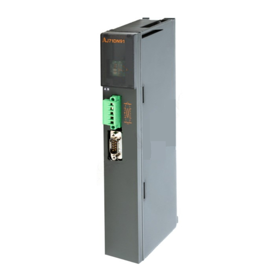
Page 11: Part Names
4. Part Names 4.1 Part Names This section describes the part names of DN91. AJ71DN91 J71DN91 DeviceNet connector L.RUN DeviceNet RS-232-C RS-232C connector A1SJ71DN91 1SJ71DN91 DeviceNet connector L.RUN DeviceNet RS-232-C RS-232C connector... -
Page 12: Handling Precautions
4.1.1 LED Display and Its Details The table below explains LED display and its details. Color Details State of LED J71DN91 name Displaying Illuminating In normal operation normal Module error detected operation illuminating Power not supplied Parameter being loaded Flickering Module error detected L.RUN Parameter being loaded... - Page 13 6. Wiring This section describes the communications cable and RS-232C cable. 6.1 Wiring Communications Cable The DeviceNet connector of DN91 is configured as illustrated below, where a seal corresponding to its cable color is adhered to the top surface of the connector. V+ (Red) CAN_H (White) Shield (drain wire)
-
Page 14: Outside Dimensions
7. Outside Dimensions (1) AJ71DN91 J71DN91 L.RUN DeviceNet RS-232-C 37.5 (0.17) (4.17) (1.48) Unit: mm (inch) - Page 15 (2) A1SJ71DN91 1SJ71DN91 L.RUN DeviceNet RS-232-C 93.6 34.5 (0.26) (3.69) (1.36) Unit : mm (inch)
-
Page 16: Warranty
WARRANTY Mitsubishi will not be held liable for damage caused by factors found not to be the cause of Mitsubishi; machine damage or lost profits caused by faults in the Mitsubishi products; damage, secondary damage, accident compensation caused by special factors unpredictable by...