
Related Manuals for Extron electronics FOX SW8 MM


Summary of Contents for Extron electronics FOX SW8 MM
- Page 1 User Guide Fiber Optic Switchers FOX SW8 8-Input Fiber Optic Switcher 68-1550-02 Rev. A 09 12...
- Page 2 Safety Instructions • English Warning Power sources • This equipment should be operated only from the power source indicated on the product. This This symbol is intended to alert the user of important operating and mainte- equipment is intended to be used with a main power system with a grounded (neutral) conductor. The third nance (servicing) instructions in the literature provided with the equipment.
-
Page 3: Fcc Class A Notice
FCC Class A Notice This equipment has been tested and found to comply with the limits for a Class A digital device, pursuant to part 15 of the FCC rules. The Class A limits provide reasonable protection against harmful interference when the equipment is operated in a commercial environment. -
Page 4: Software Commands
Selectable items, such as menu names, menu options, buttons, tabs, and field names are written in the font shown here: From the File menu, select Click the button. Copyright © 2012 Extron Electronics. All rights reserved. Trademarks All trademarks mentioned in this guide are the properties of their respective owners. -
Page 5: Table Of Contents
Contents FCC Class A Notice .......... iii Remote Control ........Specifications Availability ......... iii Remote Control Ports ........9 Simple Instruction Set ™ Control ...... 10 Host-to-interface Communications ..... 10 Introduction ..........Start-up Message ........10 About this Guide ..........1 Error Responses.......... - Page 6 FOX SW8 • Contents...
-
Page 7: Introduction
The FOX SW8 is available in two transmission modes, which define the transmission range of the switcher: FOX SW8 MM — An 8-input, 1-output multimode switcher, with a range of up to • 2000 m (6561 feet) on each input and the output •... -
Page 8: About The Fox Sw8
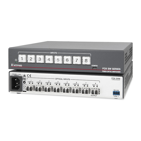
About the FOX SW8 The FOX SW8 product family consists of two products; a singlemode and a multimode ultra-high performance fiber optic switcher. The switcher accepts up to eight proprietary input optical signals from compatible Extron fiber optic transmitters (Txs) (see figure 1). The optical signal can include video, audio, and one-way (transmitter-to-receiver [Rx]) RS-232 communications. -
Page 9: Features
Features Ultra high performance — Inputs up to eight perfect, pixel-by-pixel RGBHV or digital video signals and transmits the selected signal to a compatible receiver. The switcher can handle analog video resolutions up to 1900x1200 at 60 Hz. Higher resolutions can be transmitted, but with some loss of video quality. -
Page 10: Installation And Operation
Installation and Operation The topics covered in this section are: • Rear Panel Connections Front Panel Configuration Port • • Controls, Indicators, and Operation Rear Panel Connections FOX SW8 100-240V 0.3A OPTICAL INPUTS LOOP IN LOOP IN LOOP IN LOOP IN LOOP IN LOOP IN LOOP IN... - Page 11 AC power connector — Plug a standard IEC power cord into this connector to connect the FOX SW8 to a 100 VAC to 240 VAC, 50-60 Hz power source. Transmitter Transmitter Input connectors and LEDs — OPTICAL OPTICAL Connectors — For one-way video, audio, and serial communications from the transmitter to the FOX SW8 (to be switched to the receiver) connect up to eight fiber optic cables to the input (right-hand) LC connector on...
-
Page 12: Front Panel Configuration Port
RS-232 port — For serial control of the switcher, connect a host device, such as a computer, touch panel control, or RS-232 capable PDA, via this 3-pole captive screw connector (see figure 3 to wire this connector). RS-232 Function Transmit data Tx Rx Receive data Signal ground... -
Page 13: Controls, Indicators, And Operation
Controls, Indicators, and Operation INPUTS CONFIG FOX 4G SW SERIES FIBER OPTIC SWITCHER Figure 5. FOX SW8 Front Panel Controls and Indicators Power LED — This LED lights when power is applied to the unit. Input Buttons — These buttons select the input. A button lights to indicate the selected input. -
Page 14: Operation
Operation After the transmitters, the switcher, the receivers (for the looped out and selected optical signals), and their connected devices are powered up, the system is fully operational. Select an input by pressing the desired input button. The button lights to indicate the selected input. -
Page 15: Remote Control
Remote Control The topics covered in this section are: • Remote Control Ports Simple Instruction Set™ Control • • Universal Switcher Control Program Remote Control Ports The switcher has two ports that can be connected to a host device such as a computer running the Extron DataViewer utility or the HyperTerminal utility, an RS-232 capable PDA, or a control system. -
Page 16: Simple Instruction Set ™ Control
Vx.xx 60-1171-xx (C) COPYRIGHT 20yy, EXTRON ELECTRONICS FOX SW8 SM (or MM),Vx.xx, 60-1172-xx Error Responses When the unit receives a valid SIS command, it executes the command and sends a response to the host device. If the unit is unable to execute the command because the command is invalid or it contains invalid parameters, the unit returns an error response to the host. -
Page 17: Symbol Definitions
Symbol Definitions Symbols (variables), defined below, are used in the command and response table. The symbols represent variables in the command and response table fields. = Carriage return/line feed = Carriage return (no line feed) = <Escape> key (hex 1B) = Can be used interchangeably with the character = Can be used interchangeably with the... - Page 18 ASCII Command Response Additional description Command Function (Host to Unit) (Unit to Host) Information Requests Information request •Vmt indicates the selected input. Vmt indicates the output mute status (0 = unmuted, 1 = muted).. Show firmware version is the firmware version. Example: 1.23 The factory-installed FOX SW8 controller firmware...
-
Page 19: Universal Switcher Control Program
Control Program creates the folder C:\Program Files Program Files (x86) Windows 7]\ , and it places four icons into a group folder Extron UniversalSwitcher named Extron Electronics\Universal Switcher: Check for Universal Switcher Updates • Uninstall Universal Switcher • Universal Switcher Help •... -
Page 20: Using The Program
Using the Program NOTE: The first time you connect to the Configuration (USB) port, the Found New Hardware Wizard appears (see figure 9). See “Activating a USB port for the first time,“ below. For other connections, proceed to “Starting the program,”... -
Page 21: Starting The Program
(see on page 6) or the Configuration port (see page 6). Click Start > Programs > Extron Electronics > Universal Switcher > Universal Switcher Control Program The Communication Setup window appears (see figure 10). Figure 10. Communication Setup Window If necessary, select the tab, RS-232 or USB, for the port you are using for the connection. -
Page 22: Firmware Upgrade
Operate the switcher as follows: To select an input, click the associated input button. • To mute the output, click the checkbox. Mute Video • WARNING: Risk of serious physical injury: The mute video checkbox mutes the data on the switched output only. - Page 23 on the next two screens (see figure 13). The PC downloads the firmware Click update from the Extron website and starts the Extron Installation Program to extract the firmware file. NOTE: The name, version and file size shown are sample values only. Folder where firmware is installed...
- Page 24 Click Next . The program extracts the firmware files and places them in a folder identified in the InstallShield Wizard window. NOTE: Note the folder to which the firmware file is saved. Click Finish to exit the program. Connect a computer that runs the Windows operating system to either the RS-232 port or the Configuration port of the switcher (see “Installation and Operation”...
-
Page 25: Using The Help System
NOTES: • When downloaded from the Extron website, the firmware is placed in a subfolder of C:\Program Files\Extron\Firmware • Valid firmware files must have the file extension .S19. A file with any other extension is not a firmware upgrade. • The original factory-installed firmware is permanently available on the switcher. -
Page 26: Location Of Software On The Website
By default, the Windows installation creates a C:\Program Files\Extron\ folder and places the Button Label Generator icon into a group or ButtonLabelGenerator folder named “Extron Electronics.” Using the Button Label Generator Software To run the Button Label Generator program, click >... -
Page 27: Reference Information
Part Numbers and Accessories FOX SW8 Part Numbers Models Part Number FOX SW8 SM (singlemode) 60-1171-02 FOX SW8 MM (multimode) 60-1171-01 Included Parts These items are included in each order for a FOX SW8: Included Parts Part Number IEC power cord... -
Page 28: Compatible Equipment
Compatible Equipment The FOX SW8 is compatible with the following Extron fiber optic devices: NOTE: Ensure that you match the transmission mode, singlemode or multimode, among all connected devices. Fiber Optic RGB Video Models Part Number FOX 500 (RGB) Tx/Rx (set and individual units ) 60-746-nn FOXBOX Tx/Rx VGA 60-934-nn... -
Page 29: Fiber Cables
Fiber Cables Fiber cable assemblies MHR mini high resolution cable Part Number 4LC MM LC to LC Multimode Fiber Optic Cable Assemblies 26-652-nn 2LC OM4 MM P LC to LC Laser-Optimized Multimode Fiber Optic 26-671-nn Cable Assemblies — Plenum 2LC SM P LC to LC Bend-Insensitive Singlemode Fiber Optic Cable 26-670-nn Assemblies —... -
Page 30: Button Labels
Button Labels Use either blank 8-button strips in figure 20 on the next page or the Button Label “Button Label Generator Program” on page 19). Generator software (see Installing Labels in the Switcher Buttons Install new labels in the switcher front panel buttons as follows: Make new labels and cut them out. - Page 31 Figure 20. Button Label Blanks, 8-button Strips FOX SW8 • Reference Information...
-
Page 32: Mounting The Unit
Mounting the Unit ATTENTION: Installation and service must be performed by authorized personnel only. The 1U high, half-rack width unit can be placed on a tabletop, mounted on a rack shelf, or mounted under or through a desk or other furniture, using any of the following optional kits: •... -
Page 33: Extron Warranty
Extron Electronics makes no further warranties either expressed or implied with respect to the product and its quality, performance, merchantability, or fitness for any particular use. In no event will Extron Electronics be liable for direct, indirect, or consequential damages resulting from any defect in this product even if Extron Electronics has been advised of such damage.