Table of Contents
Advertisement
Quick Links
Instruction Manual
Form 5191
September 1999
Design CAV4 Control Valve
Contents
. . . . . . . . . . . . . . . . . . . . . . . . . . . . . .
. . . . . . . . . . . . . . . . . . . . . . . . . . . . .
. . . . . . . . . . . . . . . . . . . . . . . . . . . . . . . . . .
. . . . . . . . . . . . . . . . . . . . . . . . . . . . . . .
. . . . . . . . . . . . . . . . . . . . . . . . . . . . . . . .
. . . . . . . . . . . . . . . . . . . . . . . . . . . . . .
. . . . . . . . . . . . . . . . . . . . . . . . . .
. . . . . . . . . . . . . . . . . . . . . . . . . . . . . . .
. . . . . . . . . . . . . . . . . . . . . . . . . .
. . . . . . . . . . . . . . . . . . . . . . . . . . .
. . . . . . . . . . . . . . . . . . . . . . . . . . . . . . . .
Parts List
. . . . . . . . . . . . . . . . . . . . . . . . . . . . . . . . .
Introduction
Scope of Manual
This manual includes installation, maintenance, and
parts ordering information for the Design CAV4 control
R
valve and Cavitrol
IV trim. Information on the flushing
trim is also provided. Refer to separate manuals for
information concerning the actuator, positioner, and
other accessories used with this control valve.
Only personnel qualified through training or experience
should install, operate, and maintain a Design CAV4
control valve. If you have any questions about these
instructions, contact your Fisher Controls sales office
or sales representative before proceeding.
. . . . . . . . . . . . . . . . . . .
. . . . . . . . . . . . . . . . . . . . . . . . .
. . . . . . . . . . . . . . . . . . . . . . .
. . . . . . . . . . . . . . . . . . . . . . .
1
1
1
2
2
4
5
5
6
7
8
11
13
14
W2700-1*/IL
14
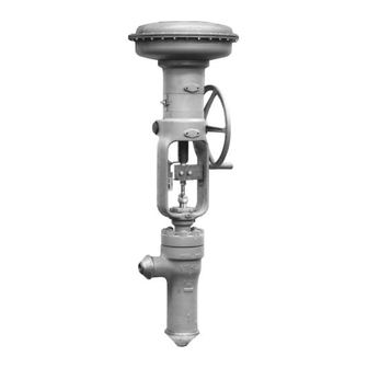
Figure 1. Design CAV4 Control Valve
with Type 657 Actuator
14
Description
The Design CAV4 control valve, shown in figure 1, is
an angle valve with soft metal-to-metal seats,
Cavitrol IV trim, cage guiding, and push-down-to-close
valve plug action. Figure 8 shows a typical balanced
TSO (tight shutoff) trim construction. Figure 10 shows
three additional valve plug constructions that are avail-
able: one with a pressure-assisted spring-loaded
PTFE seal ring with PEEK (poly ether ether ketone)
anti-extrusion rings, another with five graphite piston
rings, and a third with stem-balancing.
Cavitrol IV trim is most often used to eliminate cavita-
tion damage on liquid service where the differential
pressure drop is greater than 207 bar, differential
(3000 psi). It may also be used in applications with
lower pressure drops where its anti-cavitation perfor-
mance is required. Figure 11 shows the valve with
Design CAV4
TYPE 657
ACTUATOR
DESIGN CAV4
CONTROL VALVE
Advertisement
Table of Contents

Related Manuals for Fisher Design CAV4


Summary of Contents for Fisher Design CAV4
-
Page 1: Table Of Contents
....... . . Description The Design CAV4 control valve, shown in figure 1, is Introduction... -
Page 2: Specifications
TSO (Tight Shutoff) Trim: Valves with TSO trim Common Characteristics: Four-stage Cavitrol IV are factory tested to a more stringent Fisher trim with soft metal-to-metal seats in Design CAV4 Controls test requirement of no leakage at time of angle valve. Valve plug action is push-down-to- shipment using ANSI/ISA Class V procedures. - Page 3 Fisher Controls sales office tioned so as to cause no damage to tub- or sales representative. ing or any accessories.
-
Page 4: Principle Of Operation
Design CAV4 WARNING Personal injury could result from pack- ing leakage. Valve packing was tight- ened prior to shipment; however, the packing might require some readjust- ment to meet specific service condi- tions. Flushing the Pipeline Before flushing the piping system, install the Design... -
Page 5: Maintenance
Process fluids may spray W3671-3*/IL out under pressure when removing the packing hardware or packing rings, or Figure 3. Schematic of Design CAV4 Valve with when loosening the packing box pipe Cavitrol IV Trim plug. Packing Lubrication... -
Page 6: Packing Maintenance
Design CAV4 Table 5. Recommended Torque for Packing Flange Nuts STEM DIAMETER MINIMUM MAXIMUM Inch LbfSft LbfSft 19.1 25.4 31.8 1-1/4 38.1 1-1/2 69.9 2-3/4 12A7837-A B1422-1*/IL 10A9421-A AJ5428-D A2160-2/IL Figure 4. Optional Lubricator and Lubricator/Isolating Valve 19.1 mm (3/4-INCH) 25.4 mm (1-INCH) OR... -
Page 7: Packing Replacement
Design CAV4 Packing Replacement CAUTION Before performing any maintenance of the valve or When lifting the bonnet (key 12), be sure packing: Isolate the control valve from the line pres- that the valve plug and stem assembly sure, release pressure from both sides of the valve (key 4) remains on the seat. -
Page 8: Trim Removal
(key 6), and the cage gasket (key 7). The 6-inch Design CAV4 graphite piston rings (key 11) are brittle and in two During trim removal, inspect the seating surface of the pieces. - Page 9 Design CAV4 TOOL DIMENSIONS VALVE VALVE G Dia H Dia SIZE, SIZE, INCH Inch Inch Inch Inch Inch Inch Inch Inch Inch 86.1 3.390 18.8 .740 12.7 38.1 1.50 12.7 25.4 1.00 74.7 2.94 88.9 3.50 85.6 3.370 18.5 .730 Not Applicable 143.3...
- Page 10 Design CAV4 OUTER PLUG INNER PLUG CAGE PROTECTED SOFT SEAT SEAT RING A7088 / IL Figure 7. TSO (Tight Shutoff) Trim, Detail of Protected Soft Seat 2. Pull the valve plug and stem assembly (key 4) out thread type. Install eyebolts or similar devices into of the cages.
-
Page 11: Trim Replacement
(key 2) has a soft metal SEAL seat. To avoid damage to the seating surfaces, DO NOT lap this surface. If this area needs repair, contact your Fisher Controls sales representative or sales office for assistance. Trim Replacement... - Page 12 Design CAV4 d. Use the stud bolts (key 28) to prevent the power torque wrench from rotating. CAUTION Hold the power torque wrench and at- tached socket wrench extension at right angles to the cage retainer when apply- ing torque. Tilting the wrench and exten-...
-
Page 13: Use Of Flushing Trim
Gaskets (keys 6 and 7) that have not been in service parts are metal to metal and the seal is compressed (i.e., original gaskets in a Design CAV4 valve being properly. Do not damage the outer plug guide sur- installed or new gaskets for a valve already installed) faces. -
Page 14: Parts Ordering
Seal Ring/Piston Ring Construction stems. Stems and packing box constructions not sup- 6 inch 38A1946X012 plied by Fisher Controls and that do not meet Fisher Valve Plug & Stem Assembly See following tables Controls stem finish specifications, dimensional toler- Cage Retainer, heat-treated, tables chrome S17400... - Page 15 FOR 3 INCH VALVE 48A1976-C/DOC 48A1977-C/DOC 48A1975-C/DOC DETAIL OF PISTON RING CONSTRUCTION LOW TEMP DETAIL OF STEM BALANCED 6 INCH VALVE ONLY CAGE ASSEMBLY CONSTRUCTION 2 & 4 INCH VALVES Figure 10. Design CAV4 Control Valve with Cavitrol IV Trim...
- Page 16 Design CAV4 Description Part Number Packing Flange (cont’d) 127 mm (5 inch) yoke boss 25.4 mm (1 inch) stem 0V002425052 31.8 mm (1-1/4 inch) stem 0W085625052 127 mm (5 inch) yoke boss 31.8 mm (1-1/4 inch) stem 0W085625052 S31600 (316 SST) 127 mm (5 inch) yoke boss 38.1 mm (1-1/2 inch) stem...
- Page 17 Design CAV4 Description Part Number Description Part Number Yoke Locknut, steel [for 19.1 mm (3/4 inch) stem only] Spiral Wound Gasket, N06600/17N3 (not shown) 1E832723062 3 inch 17B9381X012 Seat Ring S31600 (316 SST) 3 inch 27B6291X012 Seat Ring, HT S17400 (17-4PH SST)/S31600 (316 SST)
- Page 18 Design CAV4 Keys 2*, 5*, 3*, 35*, 4*, 8*, 37*, 9*, and 10* TSO Trim Parts for Design CAV4 Valves STEM KEY 2 KEY 5 KEY 3 KEY 35 KEY 4 VALVE DIAMETER PORT, PORT, TRAVEL TRAVEL ACTUATOR ACTUATOR CHARAC-...
- Page 19 Design CAV4 Packing Set / Packing Parts STEM DIAMETER, mm (INCH) DESCRIPTION DESCRIPTION 19.1 (3/4) 25.4 (1) 31.8 (1-1/4) 38.1 (1-1/2) 69.9 (2-3/4) Packing set 1R290401012 1R290601012 1R290801012 - - - - - - Packing ring , PTFE (3 req’d)
- Page 20 Design CAV4 Cavitrol, Fisher, Fisher-Rosemount, and Managing The Process Better are marks owned by Fisher Controls International, Inc. or Fisher-Rosemount Systems, Inc. All other marks are the property of their respective owners. EFisher Controls International, Inc. 1980, 1999; All Rights Reserved The contents of this publication are presented for informational purposes only, and while every effort has been made to ensure their accuracy, they are not to be construed as warranties or guarantees, express or implied, regarding the products or services described herein or their use or applicability.