Table of Contents
Advertisement
Quick Links
Instruction Manual
D101640X012
Fisher
CV500 Rotary Globe Control Valve
™
Contents
. . . . . . . . . . . . . . . . . . . . . . . . . . . . . . . . .
. . . . . . . . . . . . . . . . . . . . . . . . . . . . .
. . . . . . . . . . . . . . . . . . . . . . . . . . . . . . . . .
. . . . . . . . . . . . . . . . . . . . . . . . . . . . . . .
. . . . . . . . . . . . . . . . . . . . . . . . . . . . . . . . . .
. . . . . . . . . . . . . . . . . . . . . . . . . . . . . . . . .
. . . . . . . . . . . . . . . . . . . . . . . . . . .
. . . . . . . . . . . . . . . . . . . . . . . . . . . .
. . . . . . . . . . . . . . . . . . . . . . . . . . . . . .
. . . . . . . . . . . . . . . . . . . . . . . . . . . .
. . . . . . . . . . . . . . . . . . . . . . . . . . . . . .
. . . . . . . . . . . . . . . . . . . . . . . . . . . . . . .
. . . . . . . . . . . . . . . . . . . . . . . . . . . . . . . . . . .
. . . . . . . . . . . . . . . . . . . . . . . . . . . . . . . . . . .
Introduction
Scope of Manual
This instruction manual provides installation, operation, maintenance, and parts ordering information for NPS 3
through 12 Fisher CV500 Cam Vee-Ball
the actuator and accessories.
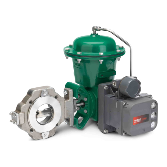
Description
The CV500 Cam-Vee-Ball rotary control valve, has a Vee-Ball style segmented ball in a valve body similar to the V500
valve. The CV500 is a flanged valve (figure 1) with a self-centering seat, eccentrically rotating V-notch ball, and splined
valve shaft. Suitable for forward or reverse flow use, this valve mates with a variety of actuators to provide throttling or
on-off service. The flanged valve mates with ASME flanges or EN flanges.
Do not install, operate, or maintain a CV500 valve without being fully trained and qualified in valve, actuator, and
accessory installation, operation, and maintenance. To avoid personal injury or property damage, it is important to
carefully read, understand, and follow all the contents of this manual, including all safety cautions and warnings. If you
have any questions about these instructions, contact your
proceeding.
www.Fisher.com
. . . . . . . . . . . . . . . . . . . . . . . . .
. . . . . . . . . . . . . . . . . . . . . . . . .
. . . . . . . . . . . . . . . . . . . . . . . .
. . . . . . . . . . . . . . . . . . . . . . . .
. . . . . . . . . . . . .
. . . . . . . . . . . . . . . . . . . .
. . . . . . . . . . . . . . . .
. . . . . . . . . . . .
™
rotary control valves. Refer to separate manuals for information concerning
Figure 1. Fisher CV500 Valve
1
1
1
2
2
3
8
8
9
9
10
10
13
15
15
18
21
22
23
X0189
Fisher CV500 VALVE WITH 2052 ACTUATOR AND
23
™
FIELDVUE
23
28
Emerson sales office
DVC6200 DIGITAL VALVE CONTROLLER
or Local Business Partner before
CV500 Valve
June 2017
Advertisement
Table of Contents

Related Manuals for Fisher CV500


Summary of Contents for Fisher CV500
-
Page 1: Table Of Contents
Description The CV500 Cam‐Vee‐Ball rotary control valve, has a Vee‐Ball style segmented ball in a valve body similar to the V500 valve. The CV500 is a flanged valve (figure 1) with a self‐centering seat, eccentrically rotating V‐notch ball, and splined valve shaft. -
Page 2: Specifications
Specifications Specifications for the CV500 rotary control valve are listed in table 1. Educational Services For information on available courses for Fisher CV500 valves, as well as a variety of other products, contact: Emerson Automation Solutions Educational Services - Registration Phone: 1-641-754-3771 or 1-800-338-8158 E-mail: education@emerson.com... -
Page 3: Installation
2. For hot water or steam service, limit maximum temperature to 260_C (500_F). 3. The pressure or temperature limits in this table or in any applicable code limitation, should not be exceeded. 4. Standard Fisher material offerings in Europe only. 5. S17400 (17‐4PH SST) shaft only. - Page 4 3. A CV500 valve is normally shipped as part of a control valve assembly, with a power or manual actuator mounted on the valve. If the valve and actuator have been purchased separately or if the actuator has been removed from the valve, mount the actuator according to the actuator instruction manual.
- Page 5 Instruction Manual CV500 Valve June 2017 D101640X012 Figure 2. Index Marks for Actuator Lever Orientation ACTUATOR ACTUATOR POSITION VALVE OPEN MOUNTING STYLE STYLE A (PDTC) RIGHT‐ HAND STYLE B (PDTO) STYLE C (PDTO) LEFT‐ HAND STYLE D (PDTC) NOTES: 1. ARROW ON LEVER INDICATES DIRECTION OF ACTUATOR THRUST TO CLOSE VALVE.
- Page 6 Instruction Manual CV500 Valve June 2017 D101640X012 Line Studs (Key 36) Cap Screws (Key 37) Valve Valve Bolt Length, Bolt Length, Overall Size, NPS Size, NPS Bolt Size Bolt Size Length, mm PN 10‐40 M16 x 2 PN 10‐40 M16 x 2 PN63 M20 x 2.5...
- Page 7 WARNING A CV500 drive shaft is not necessarily grounded when installed in a pipeline unless the shaft is electrically bonded to the valve. To avoid personal injury or property damage resulting from the effects of a static electricity discharge from valve components in a hazardous atmosphere or where the process fluid is combustible, electrically bond the drive shaft (key 3) to the valve according to the following step.
-
Page 8: Maintenance
See the instruction manual titled Fisher ENVIRO‐SEAL Packing System for Rotary Valves (D101643X012) for packing instructions. If you wish to convert your present packing arrangement to ENVIRO‐SEAL packing, refer to the retrofit kits listed in the parts kit sub‐section near the end of this manual. -
Page 9: Stopping Leakage
Inspect the shaft and packing box wall for nicks or scratches when performing the following procedures. Replacing Packing Note If the valve has ENVIRO‐SEAL live‐loaded packing installed, see the manual entitled Fisher ENVIRO‐SEAL Packing System for Rotary Valves (D101643X012). This procedure may be performed without removing the actuator from the valve if adding PTFE/composition packing rings as a temporary measure. -
Page 10: Replacing Retainer, Seat Ring, And Face Seals
Instruction Manual CV500 Valve June 2017 D101640X012 4. Remove the old packing rings (key 13), packing box ring (key 17), and, if used, the lantern ring (key 18). Do not scratch the valve shaft or packing box wall; scratching these surfaces could cause leakage. Clean all accessible metal parts and surfaces to remove particles that would prevent the packing from sealing. - Page 11 Instruction Manual CV500 Valve June 2017 D101640X012 Figure 4. Packing Arrangements PACKING RING (KEY 13) ZINC PACKING WASHERS RINGS (KEY 13) (KEY 28) LANTERN RING (KEY 18) LANTERN RINGS (KEY 18) ZINC WASHERS PACKING (KEY 28) PACKING BOX RING BOX RING...
- Page 12 Instruction Manual CV500 Valve June 2017 D101640X012 Figure 4. Packing Arrangements (Continued) ANTI-EXTRUSION RING (KEY 106) PACKING RING (KEY 108) ANTI-EXTRUSION RING (KEY 109) LANTERN RING (KEY 110) GRAPHITE PACKING SET (KEY 105) ANTI-EXTRUSION RING (KEY 106) PACKING BOX RING...
-
Page 13: Assembly
Instruction Manual CV500 Valve June 2017 D101640X012 3. Rotate the drive shaft (key 3) to move the ball (key 2) into the open position. Note The retainer (key 5) was installed at the factory using the torque listed in figure 5. - Page 14 Instruction Manual CV500 Valve June 2017 D101640X012 Table 5. Data for Making and Using the Retainer Tool VALVE SIZE, (SQUARE) (SQUARE) Inches 79.2 33.3 41.4 19.0 3.12 1.31 1.62 104.6 33.3 41.4 25.4 4.12 1.31 1.62 1.00 155.4 38.1 11.2 63.5...
-
Page 15: Replacing Ball, Shaft, And Bearings
Instruction Manual CV500 Valve June 2017 D101640X012 Insert a screwdriver, pry bar, or similar tool between the lower ear of the ball and the valve body. Use the pry to move the ball tightly against the thrust washer and bearing stop (key 7) on the actuator side of the valve. Keep the ball in that position until you finish installing the seat ring. - Page 16 Instruction Manual CV500 Valve June 2017 D101640X012 Do not drive the actuator parts off the valve drive shaft since this could move the valve bearings, shafts, and ball away from proper alignment, causing improper seating of the ball. Such misalignment may result in damage to valve components if the valve is returned to service without disassembly and inspection of the ball alignment.
- Page 17 Instruction Manual CV500 Valve June 2017 D101640X012 opposite side of the ear is a smaller hole where the chamfered end of the expansion pin rests on the inner lip of the hole. 9. For NPS 10 and 12, drive out the groove pin that secures the ball to the drive shaft. Remove the groove pin from the ball ear in the direction shown in figure 6.
-
Page 18: Assembly
Instruction Manual CV500 Valve June 2017 D101640X012 D Knock or pry the bearing out, or D Use the valve drive shaft as a piston to drive the bearing from the valve body. To accomplish this, install the pipe plug (key 29). Fill the bearing bore with a heavy grease and then insert the end of the shaft back through the valve body and into the grease‐filled bearing. - Page 19 Instruction Manual CV500 Valve June 2017 D101640X012 CAUTION To avoid damage to O‐rings resulting from contact with sharp edges within the bearing holes, use appropriate care when installing the O‐rings. 3. Slide the bearing for the follower shaft (key 6) located opposite the packing box and, if used, O‐rings (keys 19 and 20) into the valve body.
- Page 20 Instruction Manual CV500 Valve June 2017 D101640X012 8. Hold the thrust washer (key 12) between the ball (key 2) and the bearing installed next to the packing (key 6 for NPS 3 through 8 and key 42 for NPS 10 and 12).
-
Page 21: Adjusting Actuator Travel
Instruction Manual CV500 Valve June 2017 D101640X012 12. Secure the ball to the drive shaft (key 3) as follows: D For NPS 3 through 8: a. The holes in both the drive shaft (key 3) and the ear of the ball are offset from center. Make certain the holes in the ear of the ball will align with the hole in the drive shaft. -
Page 22: Changing Valve Flow Direction
Any of the Fisher pneumatic, electric, electrohydraulic, or manual actuators‐‐or any other actuator‐‐must be adjusted for use with a CV500 valve so that the ball is rotated to the fully closed position. A gap of approximately 0.0254 mm (0.001 inch) for temperatures to 260_C (500_F) or 0.1524 mm (0.006 inch) for higher temperatures measured between the seat ring (key 5) and retainer (key 4) indicates the fully closed position. -
Page 23: Changing Actuator Mounting Style
Use only genuine Fisher replacement parts. Components that are not supplied by Emerson Automation Solutions should not, under any circumstances, be used in any Fisher valve, because they may void your warranty, might adversely affect the performance of the valve, and could cause personal injury and property damage. - Page 24 D101640X012 Retrofit Kits for ENVIRO‐SEAL Packing Retrofit kits include parts to convert existing CV500 valves with single depth packing box to the ENVIRO‐SEAL packing box construction. Retrofit kits include single PTFE or graphite packing box construction (see the following table).
- Page 25 Instruction Manual CV500 Valve June 2017 D101640X012 Figure 9. Fisher CV500 Valve, NPS 3 Through 8 TCM SEAL DOUBLE PACKING SEALED BEARING APPLY LUB KEY NUMBERS NOT SHOWN ARE 28, 30, 31, 33, 36, 37, 130, AND 131 NOTE: MEASURE GAP HERE...
- Page 26 Instruction Manual CV500 Valve June 2017 D101640X012 Figure 10. Fisher CV500 Valve, NPS 10 and 12 DOUBLE PACKING SEALED BEARING APPLY LUB KEY NUMBERS NOT SHOWN ARE 28, 30, 31, 33, 36, 37, 130, AND 131 NOTE: MEASURE GAP HERE...
- Page 27 Instruction Manual CV500 Valve June 2017 D101640X012 Figure 11. Typical ENVIRO‐SEAL Rotary Packing Arrangements with PTFE Packing 42B8445‐B SINGLE PTFE PACKING STANDARD DEPTH BOX 14B0095‐A STACKING ORDER OF PTFE PACKING RINGS 42B8445‐B 42B8445‐B DOUBLE PTFE PACKING DOUBLE PTFE PACKING WITH LEAKOFF...
-
Page 28: Parts List
Responsibility for proper selection, use, and maintenance of any product remains solely with the purchaser and end user. Fisher, Vee-Ball, FIELDVUE, and ENVIRO-SEAL are marks owned by one of the companies in the Emerson Automation Solutions business unit of Emerson Electric Co.