Table of Contents
Advertisement
Quick Links
Instruction Manual
Form 5116
July 2010
Types 1808 and 1808A Pilot-Operated Relief
Valves or Backpressure Regulators
WARning
!
Failure to follow these instructions or
to properly install and maintain this
equipment could result in an explosion
and/or fire causing property damage and
personal injury or death.
Fisher
backpressure regulators or
®
relief valves must be installed, operated,
and maintained in accordance with
federal, state, and local codes, rules
and regulations, and Emerson Process
Management Regulator Technologies,
inc. instructions.
if a leak develops or if the outlet
continually vents gas, service to the
unit may be required. Failure to correct
trouble could result in a hazardous
condition. Only a qualified person must
install or service the unit.
Call a gas service person to service
the unit. Only a qualified person must
install or service the regulator.
introduction
Scope of the Manual
This manual provides installation, adjustment,
maintenance, and parts ordering information for
Types 1808 and 1808A pilot-operated relief valves or
backpressure regulators. The manual also includes
coverage of the Types 6358 and 6358B pilots and, if
used, a P590 Series filter. Instructions and parts lists
for other equipment used with these regulators are
found in separate manuals.
Description
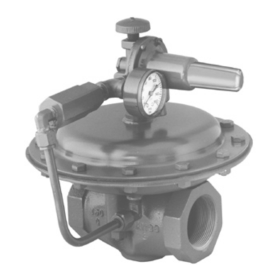
Types 1808 globe-body and 1808A angle-body,
pilot-operated backpressure regulators or relief valves
Types 1808 and 1808A
W3716
W3507
Figure 1. Types 1808 and 1808A Pilot-Operated
Relief Valves or Backpressure Regulators
are economical, compact devices used in either
gas or liquid service to maintain pressure on oil and
gas separators and in pressure relief applications
in gas distribution systems. The Type 6358 pilot is
used in backpressure regulation and pressure relief
applications throughout the oil and gas production
industry, and is used in either gas or liquid service.
Pressure relief and liquid service applications in
www.fisherregulators.com
TyPE 1808 glOBE-BODy
TyPE 1808A AnglE-BODy
Advertisement
Table of Contents

Related Manuals for Fisher 1808


Summary of Contents for Fisher 1808
- Page 1 TyPE 1808A AnglE-BODy maintenance, and parts ordering information for Figure 1. Types 1808 and 1808A Pilot-Operated Types 1808 and 1808A pilot-operated relief valves or Relief Valves or Backpressure Regulators backpressure regulators. The manual also includes coverage of the Types 6358 and 6358B pilots and, if used, a P590 Series filter.
-
Page 2: Specifications
1E392527022 Yellow 0.148 (3,76) 2.00 (51,0) 35 to 125 (2,4 to 8,6) 1k748527202 0.192 (4,88) 2.19 (55,6) Table 2. Types 1808 and 1808A Flow Coefficients FlOW COEFFiCiEnTS iEC Sizing COEFFiCiEnTS (WiDE-OPEn) TyPE 1808 1410 40.1 0.79 35.2 0.78 0.50 0.89... - Page 3 PRESSuRE ATMOSPhERiC PRESSuRE OuTlET/ExhAuST PRESSuRE lOADing PRESSuRE E0075 Figure 2. Type 1808 with 6358 Series Operational Schematics Relief Valve Backpressure Regulator As long as the inlet pressure is below set pressure, As long as inlet pressure remains below setpoint, the the pilot control spring keeps the valve plug closed.
-
Page 4: Installation
Maximum inlet pressures depend upon body material complies with the flow arrow on the main valve and temperature. See the Specifications section body (Type 1808) or runs in through the bottom for the maximum inlet pressure of the valve. The connection and out the side connection valve should be inspected for damage after any (Type 1808A). -
Page 5: Maintenance
Types 1808 and 1808A Adjustment Maintenance Parts are subject to normal wear and must be WARning inspected and replaced as necessary. Frequency of inspection and maintenance depend upon severity of The allowable spring range is stamped service conditions. The main valve body need not be on the nameplate. - Page 6 Types 1808 and 1808A Types 6358 and 6358B Pilots 7. Disconnect the pilot tubing, and unscrew the pilot from the upper casing (key 1). This procedure is performed if inspecting or replacing 8. Remove the cap screws (key 15) and the hex any pilot parts.
-
Page 7: Parts Ordering
Parts list Corrosive (NACE), Brass Type P593-1 Pipe Nipple Main Valve Types 1808 and 1808A Galvanized steel (standard) - - - - - - - - - - - Zinc-plated steel (NACE) - - - - - - - - - - -... - Page 8 Types 1808 and 1808A 47A7696-A 47A7696-A Figure 3. Type 1808A Assembly...
- Page 9 Types 1808 and 1808A 45A7841-D Figure 4. Type 1808 Assembly A7008 Figure 5. P590 Series Filter Assembly...
- Page 10 Types 1808 and 1808A P590 Series Description Part number Description Part number Filter Body Connector Cap Type P594-1, Brass 1E312414012 18-8 Stainless steel 16A2921X012 Type P593-1 (NACE), Aluminum 1E3124X0022 316 Stainless steel 16A2921X022 Filter Element, Cellulose 1E312606992 Spring Filter Head...
- Page 11 Types 1808 and 1808A A6920 TyPE 6358 PilOT inTERiOR ViEW B2619-2 TyPE 6358B PilOT inTERiOR ViEW Figure 6. Types 6358 and 6358B Pilot Assemblies...
- Page 12 For further information visit www.fisherregulators.com The Emerson logo is a trademark and service mark of Emerson Electric Co. All other marks are the property of their prospective owners. Fisher is a mark owned by Fisher Controls, Inc., a business of Emerson Process Management.