Table of Contents
Advertisement
Quick Links
Instruction Manual
Form 5374
March 2000
Design V260 Rotary Pipeline Ball Valve
Contents
. . . . . . . . . . . . . . . . . . . . . . . . . . . . . . .
. . . . . . . . . . . . . . . . . . . . . . . . . . . . .
. . . . . . . . . . . . . . . . . . . . . . . . . . . . . . . . . .
. . . . . . . . . . . . . . . . . . . . . . . . . .
. . . . . . . . . . . . . . . . . . . . . . . . . . . . . . . . .
. . . . . . . . . . . . . . . . . . . . . . . . . . . . . . .
. . . . . . . . . . . . . . . . . . . . . . . . . .
. . . . . . . . . . . . . . . . . . . . . . . . . .
. . . . . . . . . . . . . . . . . . . . . . . . . . . . . . .
. . . . . . . . . . . . . . . . . . . . . . . . . . . . . . . . . .
. . . . . . . . . . . . . . . . . . . . . . . . . . . .
. . . . . . . . . . . . . . . . . . . . . . . . . . . . . . . . . .
Introduction
Scope of Manual
This instruction manual provides installation, opera-
tion, maintenance, and parts information for the De-
sign V260 control valve. Refer to separate manuals
for information concerning the actuator, positioner, and
accessories (see figure 1).
Only personnel qualified through training or experience
should install, operate, and maintain Design V260
valves. If you have any questions about these instruc-
tions, contact your Fisher Controls sales office or sales
representative before proceeding.
. . . . . . . . . . . . . . . . . . . . . . . .
. . . . . . . . . . . . . . . . . . . . . . . .
. . . . . . . . . . . . . . . .
. . . . . . . . . . . . . . . . . .
1
1
1
2
2
4
4
4
4
6
7
9
9
9
11
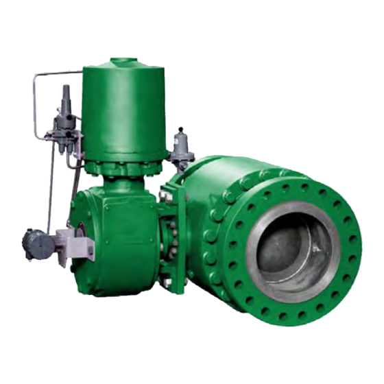
W6365-2/IL
11
Figure 1. Type V260 Sectional View
Description
The Design V260 throttling ball valves are available in
single-seal, double block-and-bleed, dual-seal, and
bidirectional flow constructions with or without attenua-
tors. Valves with dome-style attenuators combine the
efficiency of a rotary valve with the noise reducing ca-
pability of a special trim (figure 4). Valves without at-
tenuators present little or no restriction to flow at full
travel.
Design V260
Advertisement
Table of Contents

Related Manuals for Fisher Design V260


Summary of Contents for Fisher Design V260
-
Page 1: Table Of Contents
Description tion, maintenance, and parts information for the De- sign V260 control valve. Refer to separate manuals The Design V260 throttling ball valves are available in for information concerning the actuator, positioner, and single-seal, double block-and-bleed, dual-seal, and accessories (see figure 1). -
Page 2: Specifications Table
Modified equal percentage Flow and Shutoff Direction Approximate Weight Unidirectional flow for Design V260 is forward flow. Seal is upstream. See table 2 1. The pressure-temperature limits in this instruction manual and any applicable standard or code limitation for valve should not be exceeded. - Page 3 Tighten flange bolting in a criss- ing installed, an initial re-adjustment may not be re- cross sequence to ensure the flange gaskets are quired, depending on your application. See the Fisher loaded evenly. Controls instruction manual titled ENVIRO-SEAL Pack- ing System for V-Linet and ediscr Rotary Valves for packing instructions and adjustments (see figure 3).
-
Page 4: Maintenance
The frequency of inspection and replacement depends upon the se- Packing Maintenance verity of service conditions. Because of the care Fisher Controls takes in meeting all manufacturing require- ments (heat treating, dimensional tolerances, etc.), Note use only replacement parts manufactured or furnished by Fisher Controls. - Page 5 Design V260 DRIVE SHAFT (KEY 20) PACKING STUD AND NUT (KEYS 100 & 101) PACKING FLANGE (KEY 102) PACKING FOLLOWER (KEY 114) TYPICAL PTFE V-RING PACKING SET (KEY 105) TYPICAL ENVIRO-SEAL PTFE V-RING PACKING BOX PACKING SET RING (KEY 107)
-
Page 6: Seal Ring Maintenance
Design V260 Assembly Disassemble the valve only to the extent necessary to accomplish the needed inspection and repairs. For If the valve is equipped with the ENVIRO-SEAL pack- some repairs (for example, the trim parts only) com- ing system, refer to the ENVIRO-SEAL Packing Sys- plete disassembly of the valve is not necessary. -
Page 7: Assembly
Design V260 Note the valve body. Lift the ball and set it on a clean soft surface. If the packing is in good condition, it is possible to remove and replace the seal 12. Remove the two bearing plates and thrust wash- assembly, or dome assembly without ers (key 4 and 30) from the ball (key 11). - Page 8 Design V260 dome spacer into the tailpiece, using the two threaded 11. Carefully lower the ball and bearing plates onto holes as lifting lugs. the lower (inlet) tailpiece taking care not to damage the ball surface. 4. Apply Loctite to and install the two cap screws (key...
-
Page 9: Actuator Mounting
Design V260 26. Install the hex nuts (key 19) on the studs (key 3) Table 3. Torque Values and hand-tighten them. Torque all the hex nuts evenly VALVE BODY HEX NUT MOUNTING FLANGE VALVE to the values shown in table 3. - Page 10 Design V260 HI-DENSITY CHARACTERIZED ATTENUATOR ATTENUATOR DOC/IL Figure 4. Ball Attenuator Construction Details DOC/IL Figure 5. Exploded View of Dome, Ball, Tailpiece and Bearing Plates...
-
Page 11: Parts Ordering
Tailpiece, Outlet, LCC If you need a valve body as a replacement part, order the Standard Const. valve size, ANSI Class, serial number, and desired material. 8-inch Contact your Fisher Controls sales office or sales represen- Class 300 47B3246X052 tative. Class 600... - Page 12 Design V260 Description Part Number Description Part Number Attenuator Dome for Dual Seal See following table Body Hex Nut (cont’d) 12-inch (48 req’d) 1H1052X0032 Ball 16-inch (56 req’d) 18B1486X022 Standard 20-inch (56 req’d) 1A5013X0042 8-inch 47B1327X012 Drive Shaft 10-inch 47B1328X012...
- Page 13 Design V260 Description Part Number Description Part Number Plug, V260A Packing Flange 8-inch 27B3030X012 8-inch 24B3484X012 10- & 12-inch 27B3031X012 10- & 12-inch 34B3301X012 16-inch 27B4964X012 16-inch 37B3074X012 20-inch 27B5036X012 20-inch 37B3069X012 Drive Screw (not shown) 1B848024052 105* Packing Set...
- Page 14 Design V260 STANDARD FLOW DIRECTION ATTENUATOR DOME WITH NO SEAL NOTE: KEY NUMBERS 25, 33, 34, AND 35 ARE NOT SHOWN. 54B9811-C/DOC Figure 6. Type V260 Valve Assembly...
- Page 15 Design V260 Keys 9 & 17 Seal Assembly SEAL PART NUMBER VALVE VALVE Key 9 (Outlet) – for dual seal constructions Key 17 (Inlet) – for single and dual seal constructions SIZE, SIZE, NACE NACE INCHES PTFE/PEEK Delrin NACE Delrin...
- Page 16 Design V260 Fisher, Fisher-Rosemount, and Managing The Process Better are marks owned by Fisher Controls International, Inc. or Fisher-Rosemount Systems, Inc. All other marks are the property of their respective owners. This product may be covered under one or more of the following patents: 5,129,625, 5,131,666, 5,056,757, 5,230,498, 5,299,812, and 5,180,139, or under pending patents.