Advertisement
Table of Contents
(844)278-03-48,
(495)268-04-70,
Instruction Manual
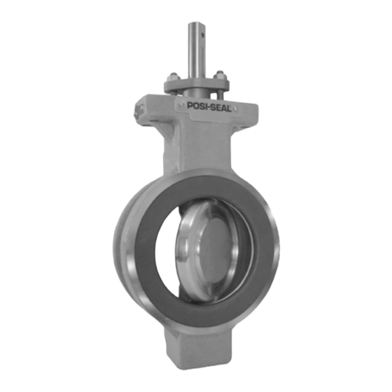
Fisherr A41 High Performance Butterfly Valve
Contents
Introduction
...............................................................
Scope of Manual
.................................................
Description
.........................................................
....................................................
Educational Services
...........................................
................................................................
...............................................
.............................................................
........................................
Disc, Drive Shaft and Bearing Maintenance for
NPS 3 through 12
.........................................
Disc, Drive Shaft and Bearing Maintenance for
NPS 2
.............................................................
...........................................
.........................................................
Repair Kits for ENVIRO-SEAL Packing
...............................................................
Introduction
Scope of Manual
This instruction manual includes installation, maintenance, and parts information for Fisher A41 high performance
butterfly valves (figure 1). Refer to separate instruction manuals for information covering the power on-off actuator
and accessories.
Do not install, operate, or maintain A41 valves without being fully trained and qualified in valve, actuator, and
accessory installation, operation, and maintenance. To avoid personal injury or property damage, it is important to
carefully read, understand, and follow all the contents of this manual, including all safety cautions and warnings. If you
have any questions about these instructions, contact your Emerson Process Management sales office before
proceeding.
Description
The A41 high performance butterfly valves have eccentrically mounted discs to reduce wear and reduce torque
requirements. The valve includes filled-PTFE or graphite packing rings that electrically bond the shaft to the valve
body. This valve has a Double D drive shaft end, and soft or metal seal rings for use in a wide variety of applications.
По вопросам продаж и поддержки обращайтесь:
(473)204-51-73,
(343)384-55-89,
(831)429-08-12,
Единый адрес: fhv@nt-rt.ru
www.fishvalve.nt-rt.ru
.....
.......................
............
..................
(843)206-01-48,
(846)206-03-16,
-
Figure 1. Fisher A41 Valve
1
1
1
2
2
5
6
9
12
13
19
20
24
26
27
27
28
W9269
28
(861)203-40-90,
(812)309-46-40,
(845)249-38-78,
A41 Valve
(391)204-63-61,
Advertisement
Table of Contents

Related Manuals for Fisher A41


Summary of Contents for Fisher A41
-
Page 1: Table Of Contents
(figure 1). Refer to separate instruction manuals for information covering the power on-off actuator and accessories. Do not install, operate, or maintain A41 valves without being fully trained and qualified in valve, actuator, and accessory installation, operation, and maintenance. To avoid personal injury or property damage, it is important to carefully read, understand, and follow all the contents of this manual, including all safety cautions and warnings. -
Page 2: Specifications
Table 1. Specifications Valve Sizes and End Connection Styles Flow Characteristic Approximately linear NPS J 2, J 3, J 4, J 6, J 8, J 10, and J 12 valves in wafer or single flanged style (NPS 2 available in Flow Direction wafer style only) See figure 4... - Page 3 Table 2. Valve Size, Shaft Diameter, and Approximate Weight APPROXIMATE WEIGHT SHAFT DIAMETER VALVE SIZE, PRESSURE Wafer-Style Single-Flange CLASS Inches Pounds Pounds 150/300/600 12.7 - - - - - - 12.7 15.9 15.9 19.1 19.1 25.4 25.4 31.8 1-1/4 31.8 1-1/4 38.1 1-1/2...
- Page 4 Figure 2. Maximum Pressure/Temperature Ratings OPERATING TEMPERATURE, _C PHOENIX III SEAL WITH PTFE INSERT PTFE AND REINFORCED PTFE SEAL UHMWPE SEAL OPERATING TEMPERATURE, _F NOTE: TEMPERATURE LIMITATIONS DO NOT ACCOUNT FOR THE ADDITIONAL LIMITATIONS IMPOSED BY THE BACKUP RING USED WITH THIS SEAL. TO DETERMINE THE EFFECTIVE TEMPERATURE LIMITATION OF THE APPROPRIATE SEAL/BACKUP RING COMBINATION, REFER TO TABLE 4.
-
Page 5: Installation
Hex Head Cap Screw and Stud Bolt Data WAFER STYLE SINGLE FLANGE STYLE CL150 CL300 CL150 CL300 VALVE SIZE, No. of Size Dia No. of Size Dia No. of Size Dia No. of Size Dia Dimen- Dimen- Dimen- Dimen- Stud Inch &... -
Page 6: Valve Orientation
CAUTION The valve configuration and construction materials were selected to meet particular pressure, temperature, pressure drop, and controlled fluid conditions specified in the customer's order. Because some body/trim material combinations are limited in their pressure drop and temperature range capabilities (especially due to differences in thermal expansion rates), do not apply any other conditions to the valve without first contacting your Emerson Process Management sales office. - Page 7 Select the appropriate gaskets for the application. Flat sheet, spiral wound (NPS 6 through 12), or other gasket types made to ASME 16.5 group or a user's standards can be used for A41 valves depending on the service conditions and applications.
- Page 8 D Flange Studs: Install two or more line flange studs into the line flanges to help hold the valve in position while centering the valve. Carefully center the valve on the flanges to ensure disc clearance. D Select and install two pipeline gaskets. D Flange Cap Screws: If line flange cap screws are used, be certain the cap screw threads engage the tapped holes to a depth equal to the flange cap screw diameter.
-
Page 9: Maintenance
Figure 4. Flow Direction RETAINER RING SIDE RETAINER RING SIDE MFG LABEL MFG LABEL FLOW ARROW FLOW ARROW ARROW SHOWS PREFERRED FLOW DIRECTION FOR SOFT SEALS AND NPS 2 METAL SEAL ARROW SHOWS FLOW DIRECTION FOR NOVEX METAL SEAL, AND PREFERRED FLOW DIRECTION FOR PHOENIX METAL SEAL FORWARD FLOW REVERSE FLOW... - Page 10 CAUTION It is possible to damage the valve if the actuator travel stops are not properly adjusted before stroking the valve. WARNING Avoid personal injury or property damage from sudden release of process pressure or bursting of parts. Before performing any maintenance operations: D Do not remove the actuator from the valve while the valve is still pressurized.
- Page 11 Figure 5. Optional Shaft-to-Valve Body Bonding Strap Assembly ACTUATOR VALVE BODY 37A6528-A VIEW A-A A3143-2 Stopping Leakage For PTFE-filled or graphite standard packing arrangements covered in this manual, often leakage from the packing can be stopped by tightening the packing flange nuts just enough to stop the leak. Use caution when tightening the nuts, overtightened nuts can damage packing box parts.
-
Page 12: Packing Maintenance
CAUTION Damage to the disc (key 3) sealing surfaces may occur if the disc is not closed when the valve is being removed from the pipeline. For fail open actuators, it may be necessary to apply loading pressure to the actuator to retain the disc in the closed position while removing the valve from the pipeline. -
Page 13: Seal Ring Maintenance For Nps 3 Through 12
Clean all accessible metal parts and surfaces to remove particles that would prevent the packing from sealing. Assembly Inspect the shaft. If it is damaged, it cannot make a good seal with the packing and it must be replaced. If the leakage comes from the outside diameter of the packing, it is possible that the leakage is caused by nicks or scratches around the packing box wall. - Page 14 Figure 6. Typical Packing Arrangements PACKING FOLLOWER (KEY 102) PACKING SET (KEY 105) PACKING RING (KEY 105) PACKING BOX RING (KEY 107) GRAPHITE RIBBON PACKING PTFE V-RING PACKING STANDARD PACKING PACKING FLANGE PACKING FLANGE NUT (KEY 102) (KEY 101) REDUNDANT SHAFT RETENTION LUBRICANT (KEY 113)
- Page 15 Figure 7. Disc Rotation Indication CAUTION: DO INDICATES NOT ROTATE DISC STOP DISC INTO APPROXIMATE INDICATES THIS SECTOR DISC APPROXIMATE POSITION TO OPEN DISC POSITION ROTATE DISC IN DIRECTION SHOWN ONLY ACTUATOR END ROTATE DISC IN OF SHAFT DIRECTION SHOWN ONLY ROTATE DISC IN EITHER DIRECTION RETAINER RING...
- Page 16 1. Removing the retainer ring (key 2): For valves with press-fit retainer rings: D Place the valve on blocks with the seal retainer facing down. (Note: Position blocks so they do not restrict the retainer ring removal.) D Rotate the disc to the open position as shown in figure 7. D On the seal ring side of the retainer ring, locate one of the knock-out points machined on the retainer ring.
- Page 17 Note PTFE, NOVEX, and Phoenix Ill seal rings used in other valve types are not interchangeable with seal rings used in the A41 valve. The A41 seal rings are not interchangeable with seal rings in any other valve type. To order seal rings for this valve, provide the serial number on the valve.
- Page 18 Figure 9. Available Seal Configuration RETAINING RING VALVE (KEY 2) VALVE BODY BODY RETAINING (KEY 1) RING SPRING (KEY 5) PRESSURE-ASSISTED SEAL SEAL RING (KEY 4) HIGH PRESSURE SHUTOFF DISC DISC FACE FACE BIDIRECTIONAL SEAL B1558-3 NPS 2 METAL SEAL PTFE SEAL GRAPHITE GASKET...
-
Page 19: Seal Ring Maintenance For Nps 2
c. Lay the retainer ring on the valve body. d. Use a press or a soft-faced hammer to press the retainer ring into its groove in the valve body. CAUTION It takes a considerable amount of force with a hammer to drive the retainer ring into place. Be sure not to damage retainer ring surfaces when installing the ring. - Page 20 1. Isolate the control valve from line pressure, and relieve pressure from the valve body. Shut off and disconnect all lines from the power actuator. WARNING The edges of a rotating disc have a shearing effect that may result in personal injury. To help prevent such injury, stay clear of the disc edges when rotating the disc (key 3).
- Page 21 Disassembly 1. If necessary, loosen the packing flange nuts (key 101). This allows the drive shaft (key 8) to turn without the friction caused by the packing. 2. Remove the actuator, using the steps provided in the packing maintenance procedures above, and remove the seal ring using the steps provided in the seal ring maintenance procedures above.
- Page 22 Figure 10. Orientation of Bearing/Spacer Tab CENTER LINE OF CENTER LINE OF SHAFT BORE BODY & DISC SPACER BEARING TAB OR DISC STOP DISC SPACER TAB A6357 D For CL150 metal bearings, three piece assemblies: Metal bearings for CL150 valves are an assembly made up of three parts: disc spacer, bearing, and bearing spacer (keys 13, 6, and 7) as shown in the orientation of bearing/spacer tab shown in figure 10.
- Page 23 Figure 11. Taper Pin and Hollow Pin Removal and Installation REMOVAL TOOL DIMENSIONS INSTALLATION TOOL DIMENSIONS Shaft Shaft A D A B C Diameter Diameter 12.7 3.91 28.43 6.35 4.19 12.7 12.7 3.68 6.35 127.0 4.83 15.88 4.60 38.10 7.87 23.37 15.88 12.7...
-
Page 24: Nps
Installing the Hollow Pin and Taper Pin 4. Place the valve body on a flat working surface with the slot for the seal ring facing up. Block the valve body high enough to allow the disc to be rotated into the open position as shown in figure 11. Note Make sure that the taper pins and hollow pins are free of particulate matter before continuing. - Page 25 5. Unscrew and remove the packing flange nuts (key 12), packing followers (keys 15 and 16), and packing flanges (keys 9 and 10) if used, from both sides of the valve. Table 6. Recommended Bolt Torques for Actuator/Mounting Cap Screws and Nuts RECOMMENDED BOLT TORQUE VALVE SIZE, NPS lbSft...
-
Page 26: Actuator Mounting
Note To obtain proper shutoff, the closed position of the A41/8560 valves must be set with the disc parallel to the retaining ring. Don't use the disc stop to set the actuator travel stops. -
Page 27: Parts Ordering
Use only genuine Fisher replacement parts. Components that are not supplied by Emerson Process Management should not, under any circumstances, be used in any Fisher valve, because they may void your warranty, might adversely affect the performance of the valve, and could cause personal injury and property damage. -
Page 28: Parts List
Repair Kits for ENVIRO-SEAL Packing Repair kits include replacement parts for key 105 and 106 for the shaft diameters listed below. ENVIRO-SEAL Packing Repair Kits SHAFT DIAMETER Inches 12.7 15.9 19.1 25.4 31.8 1-1/4 38.1 1-1/2 Parts Included in Kit Description Packing set Anti-extrusion washer... - Page 29 Description Part Number Description Part Number Hex Head Cap Screw, Steel NPS 6 75B0004X052 Stud Bolt, SST NPS 8 75B0012X052 15* Backup Ring See following table NPS 10 75B0029X052 16* Gasket, Graphite NPS 12 75B0036X052 w/ Metal and Phoenix III seals Bearing (2 req'd) NPS 3 75B1124X022...
- Page 30 Description Part Number Description Part Number 1-1/2 inch 12A8935X022 1-inch 12B7442X012 1-3/4 inch 12A9057X022 1-1/4 inch 12B7454X012 ENVIRO-SEAL PTFE 1-1/2 inch 12B7466X012 1/2 inch 12B7053X012 1-3/4 inch 14B3045X012 5/8 inch 12B7402X012 107* Packing Box Ring 3/4 inch 12B7414X012 Standard and ENVIRO-SEAL Packing 1-inch 12B7438X012 1/2 inch...
- Page 31 Key 2*. Seal Retainer MATERIAL VALVE SIZE, VALVE STYLE Steel CF8M CG8M CN7M CW2M M35-1 PTFE Seal Ring 75B0385X012 75B0385X022 75B0385X032 75B0385X042 75B0385X062 75B0385X052 75B0019X012 75B0019X022 75B0019X032 75B0019X042 75B0019X062 75B0019X052 75B0041X012 75B0041X022 75B0041X032 75B0041X042 75B0041X062 75B0041X052 75B0002X012 75B0002X022 75B0002X032 75B0002X042 75B0002X062 75B0002X052 Wafer...
- Page 32 Key 9*. Hollow Pin (2 req'd) CL150 CL300 Shaft Material Shaft Material VALVE SIZE, S17400 S17400 H1075 & N08020 N10276 N05500 H1075 & N08020 N10276 N05500 S20910 S20910 75B1122X012 75B1122X082 75B1122X222 75B1122X152 75B1122X022 75B1122X092 75B1122X232 75B1122X162 75B1122X022 75B1122X092 75B1122X232 75B1122X162 75B1122X032 75B1122X102 75B1122X242...
- Page 33 Figure 12. Wafer Valve Assembly for the NPS 3 through 12 ALLOY FOLLOWER ASSY METAL BEARING PTFE SEAL CL150 NOVEX SEAL SIZE 12 CL300 PHOENIX III SEAL NOTE: KEYS 21, 22, AND 28 ARE NOT SHOWN. 75B0094-B...
- Page 34 Figure 12. Wafer Valve Assembly for the NPS 3 through 12 (continued) GRAPHITE PACKING 34B5064-A ALLOY FOLLOWER ASSY PTFE SEAL METAL BEARING CL150 NOVEX SEAL PHOENIX III SEAL SIZE 12 CL300 NOTE: KEYS 21, 22, AND 28 ARE NOT SHOWN 75B0096-B...
- Page 35 Figure 13. Valve Assembly for NPS 2 GRAPHITE PACKING TWO PIECE FOLLOWER 34B5064-A PTFE SEAL METAL SEAL NOTE: PARTS 21 AND 22 NOT SHOWN 75B0625...
- Page 36 Responsibility for proper selection, use, and maintenance of any product remains solely with the purchaser and end user. Fisher and ENVIRO-SEAL are marks owned by one of the companies in the Emerson Process Management business unit of Emerson Electric Co. Emerson Process Management, Emerson, and the Emerson logo are trademarks and service marks of Emerson Electric Co.