Table of Contents
Advertisement
Instruction Manual
D101634X012
™
Fisher
HP and HPA Control Valves
Contents
. . . . . . . . . . . . . . . . . . . . . . . . . . . . . . . . .
. . . . . . . . . . . . . . . . . . . . . . . . . . . . .
. . . . . . . . . . . . . . . . . . . . . . . . . . . . . . . . .
. . . . . . . . . . . . . . . . . . . . . . . . . . . . . . .
. . . . . . . . . . . . . . . . . . . . . . . . . . . . . . . . . .
. . . . . . . . . . . . . . . . . . . . . . . . . . . . . . . . .
. . . . . . . . . . . . . . . . . . . . . . . . . .
. . . . . . . . . . . . . . . . . . . . . . . . . . . . . .
. . . . . . . . . . . . . . . . . . . . . . . . . . . . . .
. . . . . . . . . . . . . . . . . . . . . . . . . .
. . . . . . . . . . . . . . . . . . . . . . . . . . . . . . .
. . . . . . . . . . . . . . . . . . . . . . . . . . . . . . . . . . .
. . . . . . . . . . . . . . . . . . . . . . . . . . . . . . . . . . .
Introduction
Scope of Manual
This instruction manual includes installation, maintenance, and parts information for NPS 1 through 6 HP valves with
CL900 and CL1500 ratings; NPS 1 through 2 HP with CL2500 ratings; NPS 1 through 8 HPA valves with CL900 and
CL1500 ratings; and NPS 1 through 2 HPA valves with CL2500 ratings. Refer to separate manuals for instructions
covering the actuator, positioner, and accessories.
Do not install, operate, or maintain HP series valves without being fully trained and qualified in valve, actuator, and
accessory installation, operation, and maintenance. To avoid personal injury or property damage, it is important to
carefully read, understand, and follow all the contents of this manual, including all safety cautions and warnings. If you
have any questions about these instructions, contact your
proceeding.
Unless otherwise noted, all NACE references are to NACE MR0175-2002 and MR0103.
www.Fisher.com
. . . . . . . . . . . . . . . . . . . . . . . . .
. . . . . . . . . . . . . . . . . . . . . . . . .
. . . . . . . . . . . . . . . . . . . . .
. . . . . . . . . . . . . . . . . . . . . . . .
. . . . . . . . . . . . . . . . . . . . .
. . . . . . . . . . . . . . . .
. . . . . . . . . . .
. . . . . . .
. . . . . . . . . . . . . . . . .
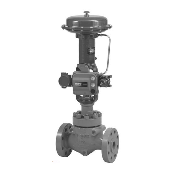
Figure 1. HP Valve with 667 Actuator and
FIELDVUE™ DVC6200 Digital Valve Controller
1
1
2
3
3
3
6
8
8
8
9
14
15
17
20
24
26
26
. .
27
27
. . .
28
30
30
36
Emerson sales office
HP and HPA Valves
or Local Business Partner before
July 2017
Advertisement
Table of Contents

Related Manuals for Fisher HPA


Summary of Contents for Fisher HPA
-
Page 1: Table Of Contents
This instruction manual includes installation, maintenance, and parts information for NPS 1 through 6 HP valves with CL900 and CL1500 ratings; NPS 1 through 2 HP with CL2500 ratings; NPS 1 through 8 HPA valves with CL900 and CL1500 ratings; and NPS 1 through 2 HPA valves with CL2500 ratings. Refer to separate manuals for instructions covering the actuator, positioner, and accessories. -
Page 2: Description
2. CL900 and CL1500 globe valves are identical for NPS 1 and 2 valves. CL900 and CL1500 globe valves for NPS 3, 4, and 6 valves, however, are not identical. 3. The centerline‐to‐face dimension for CL2500 NPS 1 and 2 HPA valves does not conform to ANSI/ISA S75.12. -
Page 3: Specifications
1428 1. Only SWE is available for CL2500. Educational Services For information on available courses for Fisher HP and HPA valves, as well as a variety of other products, contact: Emerson Automation Solutions Educational Services - Registration Phone: 1-641-754-3771 or 1-800-338-8158 E-mail: education@emerson.com... - Page 4 Instruction Manual HP and HPA Valves July 2017 D101634X012 damage, provide a relief valve for over‐pressure protection as required by government or accepted industry codes and good engineering practices. Check with your process or safety engineer for any additional measures that must be taken to protect against process media.
- Page 5 Instruction Manual HP and HPA Valves D101634X012 July 2017 Table 4. Additional Shutoff Classification per ANSI/FCI 70‐2 and IEC 60534‐4 Valve Size, NPS Port Diameter Valve Design Cage Style Leakage Class HPAD Inches Equal Percentage, Modified Equal Percentage, 73.0 2.875 Linear (std.
-
Page 6: Maintenance
Instruction Manual HP and HPA Valves July 2017 D101634X012 4. Use accepted piping and welding practices when installing the valve in the pipeline. For flanged valve bodies, use a suitable gasket between the body and pipeline flanges. 5. Install a three‐valve bypass around the valve if continuous operation is required during maintenance. - Page 7 1. For other materials, contact your Emerson sales office or Local Business Partner for torques. CAUTION The spiral‐wound gaskets are of special design. Failure to use Fisher replacement parts may result in valve damage. Figure 2. Lubricator and Lubricator/Isolating Valve LUBRICATOR 10A9421‐A AJ5428‐D...
-
Page 8: Packing Lubrication
Instruction Manual HP and HPA Valves July 2017 D101634X012 Packing Lubrication CAUTION Do not lubricate graphite packing. Graphite packing is self-lubricated. Additional lubrication may result in slip-stick movement of the valve. Note To avoid lubricants breaking down at elevated temperatures, do not lubricate packing used in processes with temperatures over 260_C (500_F). -
Page 9: Replacing Packing
Instruction Manual HP and HPA Valves D101634X012 July 2017 When using packing with a lantern ring (key 24) it may be possible to add packing rings above the lantern ring as a temporary measure without removing the actuator from the valve body. - Page 10 Instruction Manual HP and HPA Valves July 2017 D101634X012 Figure 3. Packing Arrangements UPPER WIPER (KEY 27) PACKING FOLLOWER PACKING FOLLOWER (KEY 28) (KEY 28) FEMALE ADAPTOR GRAPHITE RIBBON (KEY 35) PACKING RING (KEY 23) KEY 22 V-RING (KEY 23)
- Page 11 Instruction Manual HP and HPA Valves D101634X012 July 2017 Figure 4. Live‐Loaded Packing (KEY 214) A6297-1 39B4153-A Typical HIGH‐SEAL Graphite ULF Typical ENVIRO‐SEAL Packing System Packing System with PTFE Packing STUD (KEY 200) SPRING HEX NUT PACK (KEY 212) ASSEMBLY...
- Page 12 Instruction Manual HP and HPA Valves July 2017 D101634X012 Note The following step also provides additional assurance that the valve body fluid pressure has been relieved. 5. Hex nuts (key 14) attach the bonnet to the valve body. Loosen these nuts or cap screws approximately 3 mm (1/8 inch).
- Page 13 Personal injury or damage to equipment could occur if improper stud and nut materials or parts are used. Do not operate or assemble this product with stud(s) and nut(s) that are not approved by Emerson/Fisher engineering and/or listed on the serial card provided with this product.
-
Page 14: Trim Removal
Instruction Manual HP and HPA Valves July 2017 D101634X012 When all nuts are tightened to that torque value, increase the torque by 1/4 of the specified nominal torque and repeat the crisscross pattern. Repeat this procedure until all nuts are tightened to the specified nominal value. Apply the final torque value again and, if any nut still turns, tighten every nut again. -
Page 15: Valve Plug Maintenance
Instruction Manual HP and HPA Valves D101634X012 July 2017 Key numbers referenced in this procedure are shown in figure 17, 18, or 19, except where indicated. 1. Remove the actuator and bonnet by following steps 1 through 6 of the replacing packing procedure. Observe all warnings and cautions. - Page 16 Instruction Manual HP and HPA Valves July 2017 D101634X012 1. With the valve plug (key 5) removed according to the trim removal procedure, proceed as appropriate: For HPD and HPAD valves, the piston rings (key 8) are each in at least two sections; remove the sections from the grooves in the valve plug.
-
Page 17: Lapping Seats
Instruction Manual HP and HPA Valves D101634X012 July 2017 Lapping Seats Key numbers referenced in this procedure are shown in figure 17, 18, or 19, except where indicated. A certain amount of leakage should be expected with metal‐to‐metal seating in any valve body. If the leakage becomes excessive, however, the condition of the seating surfaces of the valve plug and seat ring can be improved by lapping. - Page 18 Instruction Manual HP and HPA Valves July 2017 D101634X012 Note HP Series valves use spiral‐wound gaskets. These gaskets provide their seal by being crushed and therefore should never be reused. This includes reusing a gasket after the lapping procedure has been performed.
- Page 19 Instruction Manual HP and HPA Valves D101634X012 July 2017 Figure 9. Typical Balanced TSO Trim, Large Port Designs (2.6875 Inch and Larger Port Diameters) VALVE PLUG SEAL PROTECTED SOFT SEAT A7096 Table 10. Actuator Groups by Type Number Group 1 Group 100 71 &...
-
Page 20: Trim Replacement
Instruction Manual HP and HPA Valves July 2017 D101634X012 Trim Replacement WARNING Observe the warning at the start of the Maintenance section. After all trim maintenance has been completed, reassemble the valve body by following the numbered steps below. Be certain that all gasketed surfaces have been well cleaned. - Page 21 Instruction Manual HP and HPA Valves D101634X012 July 2017 the valve plug stem end of the valve plug for flow‐up applications (view B of figure 20). Slide the backup ring (key 9) onto the valve plug. Secure with the retaining ring (key 10).
- Page 22 Hot torquing is not recommended. Note Stud(s) and nut(s) should be installed such that the manufacturer's trademark and material grade marking is visible, allowing easy comparison to the materials selected and documented in the Emerson/Fisher serial card provided with this product.
- Page 23 Instruction Manual HP and HPA Valves D101634X012 July 2017 FOR VALVE DIMENSIONS, mm PLUGS Part Number (See Drawing Below) FITTING (To Order A Tool) PORT SIZE (Inches) 52.324 ‐ 52.680 ‐ 55.118 ‐ 2.875 82.55 4.978 ‐ 5.029 3.708 ‐ 3.759 41.148...
-
Page 24: Retrofit: Installing C-Seal Trim
Note An installation tool must be used to properly position the C‐seal plug seal on the valve plug. A tool is available as a Fisher spare part or a tool could be manufactured following the dimensions given in figure 12. - Page 25 Instruction Manual HP and HPA Valves D101634X012 July 2017 3. Place the C‐seal plug seal over the top of the valve plug and press the C‐seal plug seal onto the plug using the C‐seal installation tool. Carefully press the C‐seal plug seal onto the plug until the installation tool contacts the horizontal reference surface of the valve plug (figure 13).
-
Page 26: Replacement Of Installed C-Seal Trim
Instruction Manual HP and HPA Valves July 2017 D101634X012 Figure 14. Stake the Threads of the C‐seal Retainer DEFORM THREAD TO STAKE C‐SEAL RETAINER PISTON RING RETAINER C‐SEAL METAL VALVE PLUG PLUG SEAL FLOW DOWN A6779 CAUTION To avoid excessive leakage and seat erosion, the valve plug must be initially seated with sufficient force to overcome the resistance of the C‐seal plug seal and contact the seat ring. -
Page 27: Lapping Metal Seats (C-Seal Constructions)
Instruction Manual HP and HPA Valves D101634X012 July 2017 Never reuse an old valve stem with a new plug or reinstall a valve stem after it has been removed. Replacing a valve stem requires drilling a new pin hole in the stem. This drilling weakens the stem and may cause failure in service. However, a used valve plug may be reused with a new valve stem. -
Page 28: Trim Replacement (C-Seal Constructions)
Note An installation tool must be used to properly position the C‐seal plug seal on the valve plug. A tool is available as a Fisher spare part or a tool could be manufactured following the dimensions given in figure 12. - Page 29 Instruction Manual HP and HPA Valves D101634X012 July 2017 Figure 16. Example of Machining the Lower (Valve Plug to Seat Ring) and Upper (C‐seal Plug Seal to Cage) Seating Surfaces C‐seal RETAINER UPPER SEATING SURFACE 0.508 (0.020) MACHINING OF THE UPPER...
-
Page 30: Parts Ordering
Use only genuine Fisher replacement parts. Components that are not supplied by Emerson Automation Solutions should not, under any circumstances, be used in any Fisher valve, because they may void your warranty, might adversely affect the performance of the valve, and could cause personal injury and property damage. - Page 31 Instruction Manual HP and HPA Valves D101634X012 July 2017 Gasket Set* (Includes Key 11 Bonnet Gasket and Key 12 Seat Ring Gasket) VALVE STYLE AND SIZE, NPS MATERIAL VALVE RATING HP Globe HPA Angle N06600/Graphite N07750/Graphite 1 (std) 1 (std)
- Page 32 Instruction Manual HP and HPA Valves July 2017 D101634X012 Figure 18. NPS 2 HPAD Valve KEY 31 AND TAPPING ARE OPTIONAL FLOW UP FLOW DOWN E1635 FLOW FLOW 53B6657 HPAD HPAS MICRO‐FLAT PLUG FLOW INLET TWO-FLAT PLUG FLOW INLET ONE-FLAT PLUG...
- Page 33 Instruction Manual HP and HPA Valves D101634X012 July 2017 Figure 19. NPS 2‐6 HPD Valve KEY 31 AND TAPPING ARE OPTIONAL FLOW HPD TRIM j APPLY LUB FLOW UP FLOW DOWN EXTENSION BONNET BAFFLE ASSEMBLY (NPS 2 ONLY) (GLOBE & ANGLE) 127 mm (5‐INCH) YOKE BOSS...
- Page 34 Instruction Manual HP and HPA Valves July 2017 D101634X012 Figure 20. NPS 2‐6 HP Valve ‐ Alternate Configurations FLOW FLOW FLOW HPT, HPAT TRIM NPS 2‐3 HPS TRIM HPS TRIM (ALL SIZES) MICRO‐FORM PLUG (NPS 2 ONLY) FLOW FLOW FLOW...
- Page 35 Instruction Manual HP and HPA Valves D101634X012 July 2017 Figure 20. NPS 2‐6 HP Valve ‐ Alternate Configurations (Continued) FLOW FLOW NPS 4 HPD TRIM HPT, HPAT TRIM WHISPER III, WHISPER III AVAILABLE IN HPD, HPAD, HPS, LEVEL D AND HPAS (NPS 2)
-
Page 36: Parts List
Responsibility for proper selection, use, and maintenance of any product remains solely with the purchaser and end user. Fisher, Cavitrol, ENVIRO-SEAL, FIELDVUE, Whisper Trim, and WhisperFlo are marks owned by one of the companies in the Emerson Automation Solutions business unit of Emerson Electric Co.