
Related Manuals for QSC CX168


Summary of Contents for QSC CX168
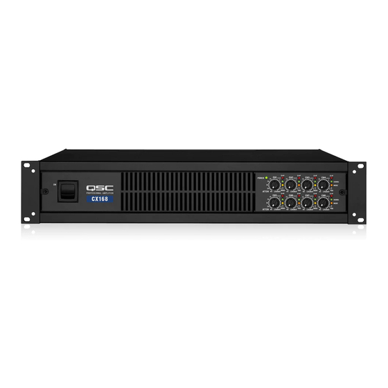
- Page 1 CX168 8-Channel Installed Sound Professional Audio Amplifier User Manual *TD-000095-00* TD-000095-00 rev.A...
-
Page 2: Important Safety Precautions
Purchased From:_____________________________ © Copyright 2001, QSC Audio Products, Inc. QSC® is a registered trademark of QSC Audio Products, Inc. The Audio Precision logo is the property of Audio Precision, Beaverton OR All trademarks are the property of their respective owners. -
Page 3: Table Of Contents
Setting the Configuration (MODE) Switches...8 Setting Operating Mode (Stereo, Parallel, or Bridge)...9 Clip Limiter Setting...10 Low Frequency (Subaudio) Filter Settings...10 Low Frequency Filtering Tips and CX168 Frequency Response Curve...11 CONNECTIONS: Inputs: Outputs: Connecting the Outputs in Stereo or in Bridge Mode ...14 OPERATION: Power Switch ...16... -
Page 4: Introduction
With information including connections, configuration and operation, it offers many useful guidelines. The CX168 provides a high level of channel density in a small, lightweight form factor ideal for multi-zone audio systems. Representing the culmination of QSC’s extensive experience... -
Page 5: Rear Panel Illustration
INTRODUCTION REAR PANEL DIMENSIONS AND MOUNTING POINTS... -
Page 6: Installation
INSTALLATION: UNPACKING & RACK MOUNTING What is Included Your CX168 shipping container, as shipped from the factory, includes: - CX168 eight channel audio power amplifier - this user’s manual - security cover (plate) for gain controls - self-adhesive rubber feet (use for non-rack mount applications) -
Page 7: Fan Cooling
COOLING & AC MAINS REQUIREMENTS Fan Cooling The CX168 amplifier draws cool air into the rear of the amplifier and exhausts hot air from the front. This is done so the equipment in the rack stays as cool as possible. This method of cooling gives the operator “direct”... -
Page 8: Setting The Configuration (Mode) Switches
SETTING THE MODE CONFIGURATION DIP SWITCHES Setup By using the mode switches and connecting to the amplifier properly, the CX168 amplifier can be configured as a 1 to 8 channel amplifier. This flexibility enables the CX168 to be used for most any multichannel application. -
Page 9: Setup
There are 4 possible channel pairs that can be bridged on the CX168. They are Ch.1-2 Bridge, Ch. 3-4 Bridge, Ch. 5-6 Bridge, and Ch. 7-8 Bridge. Any pair or number of pairs can be independently configured in bridge mode. -
Page 10: Clip Limiter Setting
SETUP: MODE SWITCHES: CLIP LIMITER AND LOW FREQUENCY FILTERS Clip Limiter The CX168 amplifier has separate clip limiters for each of the 8 channels. These clip limiters respond only to actual amplifier clipping. Amplifier clipping generates internal error signals which cause the clip limiter to quickly reduce gain and minimize the overdrive. -
Page 11: Low Frequency Filtering Tips And Cx168 Frequency Response Curve
SETUP: MODE SWITCHES: CLIP LIMITER AND LOW FREQUENCY FILTERS Low Frequency Filtering Tips: • The OFF position should be used only for subwoofer systems with rated frequency response below 33 Hz. or if low frequency filtering is provided by other devices. •... -
Page 12: Connections
CONNECTIONS: INPUTS- Using the Terminal Block Inputs Each channel has an active balanced "Euro-style" terminal block input jack. These terminal blocks allow the input wiring to be terminated using simple hand tools and allows for quick reconfiguration when needed. The input impedance is 20k ohm balanced or 10k ohm unbalanced. -
Page 13: Connecting To The Dataport Inputs
How to Connect to the DataPort: Direct mounting of DataPort accessories is NOT supported by the CX168 amplifier. Devices that are normally mounted directly to the amplifier must be mounted remotely and connected to the DataPort using a DataPort cable. -
Page 14: Outputs: Connecting The Outputs In Stereo Or In Bridge Mode
CONNECTIONS: OUTPUTS Outputs Refer to the label on the rear panel of the amplifier for proper wiring connections. The output connection for STEREO and PARALLEL modes is on the left side of the label , while the output connection for BRIDGE mode is shown to the right side of the label. -
Page 15: How To Use The 8-Pin Output Connectors
CONNECTIONS: OUTPUTS- OUTPUT TERMINAL SAFETY WARNING! Do not touch output terminals while amplifier power is on. Make all connections with amplifier turned off. Risk of hazardous energy! When selecting speaker cable (wire), always use the largest wire size and shortest length of wire practical for an installation. -
Page 16: Operation
OPERATION: POWER SWITCH and GAIN CONTROLS Power Switch The power switch is a rocker-type switch. It is located on the left side of the front panel. To turn the amplifier on, push in on the top of the switch. To turn the amplifier off, push in on the bottom of the switch. -
Page 17: Led Indicators
OPERATION: LED INDICATORS LED Indicators The LED indicators provide basic operation information to the operator. The ‘nor- mal’ indications of the LED’s are shown, below. NOTE! The BRDG and PAR mode indicator LED’s are discussed on page 9. POWER: The power ‘on’ indicator LED is located at the upper-left of the gain control cluster. -
Page 18: Gain Controls
7dB attenuation position, then the voltage gain of the amplifier is 19dB (26dB - 7 dB). Location of gain controls on the front panel of the CX168 Typical channel-pair control and indicator group on the CX168 Typical gain control showing attenuation level markings and LED’s for the channel. -
Page 19: Security Plate For Gain Controls
OPERATION: GAIN CONTROL SECURITY PLATE Gain Control Security Plate After final gain adjustments have been made, the gain controls can be covered with a security plate. This easy-to-use security plate makes it difficult for others to adjust the gain. This may be desirable in instances where the gain controls should not be tampered with. To install the security plate: Use a 9/64”... -
Page 20: Dataport Connector
DSP-3, due to the high density of connectors on the rear panel but they may be connected via cables. Using the DataPort Use a QSC DataPort cable to connect the CX168 DataPorts to DataPort accessories. Consult the accessory’s documentation for recommended mounting and interconnect information. -
Page 21: Dataport Guidelines For The Cx168
2. The DataPort for channels 1 and 2 has a special function on the CX168. It is the ‘master’ DataPort for controlling AND reporting power supply status of the amplifier. It is only possible to control and report the status of the power supply using the Ch.1 &... -
Page 22: Applications
Four Room Stereo Feed A simple application of the CX168 would be an installation with 4 rooms of coverage; each room to be provided with a stereo audio feed. All speakers are 4 ohm or greater impedance and have a frequency response rated down to 45 Hz., making them suitable for the 70 Hz. - Page 23 Low frequency filtering is used only on the LF drivers. The HF and mid range drivers have filtering before the amplifier and need no filtering from the CX168. The subwoofer cabinet can handle the low frequencies without problem, so no filtering for them. The LF...
-
Page 24: Appendix
NOTE! In the following diagrams, channels 1 and 2 are shown as examples only. Any channel pair can be configured as shown here. The channels pairs on the CX168 are : Channels 1 and 2, Channels 3 and 4, Channels 5 and 6, and Channels 7 and 8. -
Page 25: Bridge Mode
APPENDIX: DESCRIPTION OF BRIDGE OPERATING MODE Bridge Mode Bridge mode combines both output channels into one output. This mode is for driving a single, high-power-rated load with twice the “normal” voltage swing. This results in about 4 times the peak power and about three times the sustained power of a single channel. -
Page 26: Multiple Speaker Loads In Series
APPENDIX: MULTIPLE SPEAKER LOADS IN SERIES Multiple Lo-Z Loads in Series: Series connection is where the same signal current flows through each of the speaker loads. The signal goes into one terminal of the first speaker and out its other terminal; then the signal goes into one terminal of the next load, and so on. -
Page 27: Multiple Speaker Loads In Parallel
Below are examples of parallel connections of 4, 8 and 16 ohm speakers. 2 and 4 ohm parallel loads are not usable because the parallel impedance of 4 ohm loads will always be 2 ohms or less; this is too low an impedance for the CX168 amplifier. -
Page 28: Troubleshooting
• If using the DataPort connections, the channel 1 and 2 DataPort controls the power supply of the amplifier. Check whether or not the DataPort accessory connected to the CX168 is forcing the power supply into standby mode. • An amplifier which keeps tripping the AC circuit breaker may have a serious internal fault. Turn it off, remove AC power, and have the amplifier serviced by a qualified technician. - Page 29 TROUBLESHOOTING: PROBLEM: DISTORTED SOUND • INDICATION: CLIP LED FLASHING • If the red clip indicator flashes before the signal indicator does, the load impedance is abnormally low or shorted. Unplug each speaker one-by-one at the amplifier. If the clip LED goes out when you disconnect a cable, then that cable or speaker is shorted. Try another cable and speaker to locate and/or remove the fault.
-
Page 30: Specifications
VOLTAGE GAIN (gain control set to 0 dB attenuation) INPUT SENSITIVITY for rated power into 8 ohms INPUT CLIPPING, Vrms INPUT IMPEDANCE CX168 (100 watts, all channels driven) (140 watts, all channels driven) 2 dB at 4 ohms Less than 0.02% Less than 0.05%... - Page 31 1/3 power is representative of program material with severe clipping. CONTROLS DIMENSIONS WEIGHT CX168 Full short circuit, open circuit, thermal, ultrasonic and RF protection. Stable into reactive or mismatched loads. Continuously variable speed fan; back-to-front air flow through tunnel heat sink...
-
Page 32: Warranty Information
Product Warranty QSC guarantees the CX168 amplifier to be free from defective material and/or workmanship for a period of three years from the date of sale, and will replace defective parts and repair malfunctioning products under this warranty when the defect occurs under normal installation and use—provided the unit is returned to our factory via prepaid transportation with a copy of the... - Page 33 NOTES...
- Page 34 NOTES...
- Page 36 QSC Audio Products, Inc. 1675 MacArthur Boulevard Costa Mesa, California 92626 USA “QSC” and the QSC logo are registered with the U.S. Patent and Trademark Office. ©2000 QSC Audio Products, Inc.