Table of Contents
Advertisement
CX-Q & CX-Qn
Q-SYS Network Amplifiers
User Manual
CX-Q 2K4 — 4 Channel, 2000 W Network Amplifier with Mic/Line Inputs
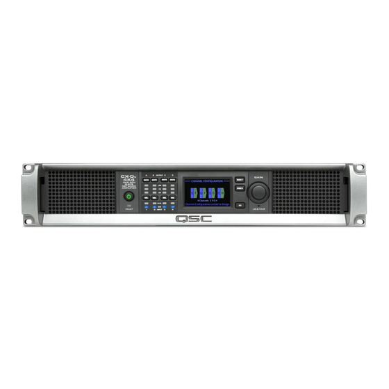
CX-Q 4K4 — 4 Channel, 4000 W Network Amplifier with Mic/Line Inputs
CX-Q 8K4 — 4 Channel, 8000 W Network Amplifier with Mic/Line Inputs
CX-Q 4K8 — 8 Channel, 4000 W Network Amplifier with Mic/Line Inputs
CX-Q 8K8 — 8 Channel, 8000 W Network Amplifier with Mic/Line Inputs
CX-Q
2K4 — 4 Channel, 2000 W Network Amplifier
n
CX-Q
4K4 — 4 Channel, 4000 W Network Amplifier
n
CX-Q
8K4 — 4 Channel, 8000 W Network Amplifier
n
CX-Q
4K8 — 8 Channel, 4000 W Network Amplifier
n
CX-Q
8K8 — 8 Channel, 8000 W Network Amplifier
n
TD-001586-01-B
*TD-001586-01*
®
Advertisement
Table of Contents

Related Manuals for QSC CX-Q Series


Summary of Contents for QSC CX-Q Series
-
Page 1: User Manual
CX-Q & CX-Qn ® Q-SYS Network Amplifiers User Manual CX-Q 2K4 — 4 Channel, 2000 W Network Amplifier with Mic/Line Inputs CX-Q 4K4 — 4 Channel, 4000 W Network Amplifier with Mic/Line Inputs CX-Q 8K4 — 4 Channel, 8000 W Network Amplifier with Mic/Line Inputs CX-Q 4K8 —... -
Page 2: Explanation Of Symbols
EXPLANATION OF SYMBOLS The term “WARNING!” indicates instructions regarding personal safety. If the instructions are not followed the result may be bodily injury or death. The term “CAUTION!” indicates instructions regarding possible damage to physical equipment. If these instructions are not followed, it may result in damage to the equipment that may not be covered under the warranty. -
Page 3: Maintenance And Repair
QSC authorized service station or an authorized QSC International Distributor. QSC is not responsible for any injury, harm or related damages arising from any failure of the customer, owner or user of the apparatus to facilitate those repairs. -
Page 4: Rohs Statement
海拔和热带条件 Only suitable for safe use in areas below 2000m above sea level 仅适用于海拔2000m 以下地区安全使用 Only suitable for safe use in non-tropical climates 仅适用于非热带气候条件下地区安全使用 Warranty For a copy of the QSC Limited Warranty, visit the QSC website at www.qsc.com TD-001586-01-B... -
Page 5: What's In The Box
What's in the Box (1x) (1x) CX-Q (2x or 1x) (1x) (8x or 4x) CX-Q or AC Cord GPIO Outputs CX-Q Inputs (16-pins) (8-Pins) Amplifier (3-Pins) CX-Q (1x) (1x) (1x) (16x or 8x) Warranty Safety Quick Start Cable Tie Information Guide Features Amplifier Front Panel... -
Page 6: Installation
Rack-Mount the Amplifier The CX-Q Series amplifiers are designed to be mounted in a standard rack-mount unit. The amplifiers are 2RU high, and 381 mm (15 in) deep. 1. Secure the amplifier in the rack with eight screws (not supplied), four in front, four in back. For complete instructions, refer to TD-000050 "Rear Rack Ears Installation Guide"... - Page 7 Analog Inputs are converted to digital audio in the CX-Q amplifiers then routed to the Q-SYS Core over the Q-LAN network. The digital signals show up in Q-SYS Designer at the CX-Q input component where they can be routed as needed. Refer to the Q-SYS documentation. 1.
- Page 8 A B C D 4 Channel E F G H 4 Channel Separate Channels (A B C D) and (E F G H) For Separate Loudspeakers OUTPUTS TO SPEAKERS OUTPUTS TO SPEAKERS Use eight 2-wire cables, connect to: • T1+/T2- (Loudspeaker A / E) CH D •...
- Page 9 Figure 11. 3. Use a Phillips screwdriver to secure the connector. IMPORTANT! The CX-Q series of audio power amplifiers are high power amplifiers designed for installation use in both Lo-Z and Hi-Z applications. Proper wiring class/size is required to ensure safe operation.
- Page 10 AC Mains WARNING! When the AC Power is on, there is a potential of having dangerous voltage at the output terminals on the rear of the amplifier. Use caution not to touch these contacts. Turn off the Power switch prior to making any connections. 1.
-
Page 11: Amplifier Modes
Amplifier Controls and Indicators — Figure 13 — CX-Q 8-Channel Shown Output Channel labels A, B, C, D, E, F, G, H Amplifier Mode button (Green/Red) 12. LCD Graphic Display Output Channel Mute buttons / LEDs (Red) Output Channel Select buttons / LEDs (Blue) 13. - Page 12 Input and Output Signal Flow CX-Q Series Amplifiers Refer to Figure 14 The CX-Q 4K8 and CX-Q 8K8 amplifiers have eight MIC/LINE inputs and eight (two blocks of four) amplified outputs on the rear of the amplifier. The CX-Q 2K4, CX-Q 4K4, and CX-Q 8K4 amplifiers have four MIC/LINE inputs and four (one block of four) amplified outputs on the rear of the amplifier.
-
Page 13: Status Screen
Screens STATUS Screen Refer to Figure 16 STATUS 1. DEVICE – the hostname (network name) of the amplifier. A default name is CX-Q DEVICE: CXDQ8CH-1234 given at the factory, similar to the example. You may change the name in the DESIGN: My Design Filename Q-SYS Configurator. - Page 14 STANDALONE OUTPUT GAINS Screen Refer to Figure 19 The STANDALONE OUTPUT GAINS screens provide a quick overview of all outputs. In STANDALONE OUTPUT GAINS addition, when this screen is displayed, you can make gain adjustments from the amplifier's Q-LAN: -8.08 dB -45.0 dB front panel.
- Page 15 CHANNEL CONFIGURATION Screens 1. Figure 21 is a graphic representation of the amplifier's output CHANNEL CHANNEL CONFIGURATION CONFIGURATION. Inputs (Q) are from Q-SYS, outputs A–D (E–H not shown) represent the amplifier output channels and their configuration. 2. Text indicating how many channels, and the output configuration. For possible configurations refer to "Possible Combinations"...
- Page 16 GPIO There are 16 General Purpose Input Output pins for use in various applications. Figure 23 shows the pin configuration for the connector on the rear of the amplifier. — Table 2 shows the connector pin-out. Figure 24 gives some simple GPIO applications. —...
-
Page 17: Specifications
Specifications Power Specifications – 4-Channel Models CX-Q 2K4 / CX-Qn 2K4 CX-Q 4K4 / CX-Qn 4K4 CX-Q 8K4 / CX-Qn 8K4 Continuous Continuous Continuous Max Power Max Power Max Power Power Power Power Configuration Loads 100 V 1000 1250 1150 70 V 1000 1250... -
Page 18: Power Specifications
Power Specifications – 8-Channel Models CX-Q 4K8 / CX-Q CX-Q 8K8 / CX-Q Continuous Continuous Configuration Loads Max Power Max Power Power Power 100 V 1000 1250 70 V 1000 1250 4 or 8 Independent Channels 16 Ω A, B, C, D, E, F, G, H 8 Ω... - Page 19 Peak Voltage Specifications – 4-Channel Models CX-Q 2K4 / CX-Qn 2K4 CX-Q 4K4 / CX-Qn 8K4 CX-Q 8K4 / CX-Qn 8K4 Max Peak Max Peak Max Peak Max Peak Max Peak Max Peak Configuration Loads Voltage Current Voltage Current Voltage Current 100 V 10.0...
-
Page 20: Operating Specifications
Operating Specifications CX-Q 2K4 CX-Q 4K4 CX-Q 8K4 CX-Q 4K8 CX-Q 8K8 CX-Qn 2K4 CX-Qn 4K4 CX-Qn 8K4 CX-Qn 4K8 CX-Qn 8K8 Typical Distortion 0.02 - 0.05% 0.02 - 0.05% 0.02 - 0.05% 0.02 - 0.05% 0.02 - 0.05% 8Ω 0.04 - 0.1% 0.04 - 0.1% 0.04 - 0.1%... -
Page 21: Full Power
Heat Loss and Current-Draw Charts Heat losses are the thermal emissions from an amplifier while it is operating. It comes from dissipated waste power—i.e., real AC power in minus audio power out. Measurements are provided for various loads at idle, 1/8 of average full power, 1/3 of average full power, and full power, with all channels driven simultaneously. -
Page 22: Current Consumption
Current Consumption NOTEE: Power Dissipation minimally varies between 100 and 240 VAC. This data is based on all operating voltages (100-240 VAC). ModelE: CX-Q 2K4 / CX-Q 120 VAC Mains 230 VAC Mains Thermal Dissipation 100 VAC AC Current Losses AC Current Losses Output Level Load... - Page 23 ModelE: CX-Q 8K4 / CX-Q 120 VAC Mains 230 VAC Mains Thermal Dissipation 100 VAC AC Current Losses AC Current Losses Output Level Load BTU/h kcal/hr Current (Amps) (Watts) (Amps) (Watts) Standby Mute All Idle 100 V /Channel 10.4 1263 70 V / Channel 10.6 1304...
- Page 24 ModelE: CX-Q 8K8 / CX-Q 120 VAC Mains 230 VAC Mains Thermal Dissipation 100 VAC AC Current Losses AC Current Losses Output Level Load BTU/h kcal/h Current (Amps) (Watts) (Amps) (Watts) Standby 46.0 Mute All 49.0 Idle 197.0 100 V / Channel 1184 70 V / Channel 1290...
-
Page 25: Customer Service
© 2019 QSC, LLC. All rights reserved. QSC the QSC logo, and the Q-SYS logo are registered trademarks of QSC , LLC in the U.S. Patent and Trademark office and other countries.