
Related Manuals for Nikon Epiphot 300


Summary of Contents for Nikon Epiphot 300
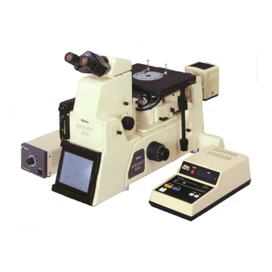
- Page 1 • • • • • • • • • • • • • ♦ • • • • • • • • • · · · · · · · � � � � � Inverted Metallurgical Microscope EPIPHOT 300...
- Page 2 Thank you for your purchase of a Nikon product. This instruction manual has been prepared for those who will use Nikon's inverted metallurgical microscope EPIPHOT 300. Before using the microscope, read this manual from cover to cover to acquire flawless knowledge of its safe operation.
-
Page 3: Follow The Instructions Below
Never disassemble parts of the instrument other than those mentioned in this manual. If any abnormality or malfunction is found in the instrument, contact your nearest Nikon representative. 3. Heat at the Lamphouse The lamp and the lamphouse are very hot during and right after the illumination. - Page 4 If they don't, never tum on the power switch. Contact your nearest Nikon representative. Detach the battery chamber cover from the bottom of the control box, and confirm that the...
- Page 5 7. Connecting or Disconnecting Cables Before connecting or disconnecting the cables, turn off the power switches of the power supply � ==----- �- - ' I l l unit and the control box. ✓" 8. Cautions when Replacing the Lamp •...
- Page 6 10. Weak Electromagnetic Waves This microscope generates weak electromagnetic waves. Do not bring precision electronic devices near the microscope. Move radios, TV sets or other similar devices away from the microscope if their reception is affected by the electromagnetic waves from the instrument.
- Page 7 12. Cautions when Carrying the Microscope (cont'd) • Never attempt to move the microscope by holding the focus knob, eyepiece tube, dark box, lamphouse, stage or the like. Such an attempt may cause any of these parts to be pulled off and damage the instrument. •...
-
Page 8: Table Of Contents
CONTENTS FOLLOW THE INSTRUCTIONS BELOW! NOMENCLATURE ..........1 NOMENCLATURE ASSEMBLY ............ 5 Ill. PREPARATION ..........15 1. Diopter Adjustment ................2. lnterpupillary Distance Adjustment ..........ASSEMBLY 3. Centering of 12V-S0W Halogen Lamp ..........18 4. Centering of Field Diaphragm ............19 5. - Page 9 NOMENCLATURE Revolving nosepiece Stage ring Objective Mirror block changeover lever OB/PHOTO changeover lever Analyzer slider (Dust-tight slider) Eyepiece tube clamp screw Rectangular mechanical stage Anti-glare NOB filter Eyepiece tube insertion/removal lever Diopter correction ring Polarizer slider (Dust-tight slider) Eyepiece Lamphouse Pilot lamp Control box Lamp...
- Page 10 Screw holes for field diaphragm centering Field diaphragm dial Screw holes for aperture Mirror block port diaphragm centering DX cable Lamphouse adapter 35 mm dark box Filter :,:, Filter pocket 35 mm dark box Side port attaching mount Reticle slider (Dust-tight slider) Lamp intensity control dial Aperture diaphragm dial AC IN connector...
- Page 11 Control box CHECK display D.EXP [double exposure] key Exposure time display EXP [exposure] key EXP.ADJ [exposure adjustment] key RST [reset] key ISO keys Film end LED DX mode displ ay lamp WIND key ISO valu e displ ay EXP.ADJ [exposure adjustment] value display DX cable Fuse (1A/250V) Power switch...
- Page 12 FX-35DX Rewind switch Film advance mode switch Advance button Rewind knob Rewind crank (") Attaching/detaching button 1-- ,____ _ _ _ __ _ _ _ D X _C _ o _ n n _ e _ c t _ o r NFX-35 Film advance indicator Data mask IN/OUT lever...
- Page 13 • Use 12V-100W halogen lamp (specified in 'Electrical Specifications' on page 72) and the adapter. Nikon 12V-l OOW lamphouse 2 with pre Insert two of them into the two screw holes in centered socket, the upper part of the adapter. Tighten these two •...
- Page 14 Loosen the clamp screw on the side of the @ Revolving Nosepiece lamphouse cover with a coin or the like [I], and detach the cover [21. Sufficiently loosen the nosepiece clamp screw Press down the lamp clamp lever. While with the hexagonal screwdriver. Fit the circular pressing it down, insert the lamp into the socket dovetail of the nosepiece to the corresponding until the lamp pins reach the limits in the...
-
Page 15: Eyepiece Tube
Rubber eyeguards for binocular ® Eyepiece Tube eyepieces (option) Insert each eyeguard into the groove in the outer Sufficiently loosen the eyepiece tube clamp circumference of the eyepiece. screw at the top of the microscope with the hexagonal screwdriver. Slightly tilt the eyepiece tube to push its dovetail into the corresponding mount. - Page 16 � For 100-120 V area Use only the power supply unit model "PSM- 1120" provided by Nikon Corporation. For 220-240 V area -------� Use only the power supply unit model "PSM- 2120" provided by Nikon CorporatiolL Turn off the power switch of the power supply •...
- Page 17 �,,,,.,, Ni-Cd battery � Do not dispose of used or disused batteries. Return them to your nearest Nikon representative. Turn off the power switch of the control box before connecting the cables. • Connect the control box to the microscope base with the signal cable.
- Page 18 • Align the index of the dark box with that of ® Dark Box 35 mm dark box attaching mount of the microscope base. Rotate the dark box in the Use the FX-35DX dark box or the NFX-35 dark arrow direction to the limit to attach the dark box for 35 mm film photomicrography.
- Page 19 @ Photomicrographic @ Analyzer, Polarizer and Reticles Attachment (option) • Hold each slider with its indications facing up Refer to the instruction manual of your photo or toward you, and insert it into the micrographic attachment on its assembly or on corresponding port.
- Page 20 'Electrical Specifications' on page 72) and different ways depending on the type of a the Nikon 12V-50W lamphouse for U-epi projection Jense to be used. • Use of a lx relay lens •...
- Page 21 • Lamp and Lamphouse Use of the Metal Halide Light Source Insert the lamp firmly into the socket pinholes Insert the end of the fiber into the fiber adapter [I] . Fit the socket sleeve into the lamphouse until it reaches the limit. Fix this end of the fiber �...
-
Page 22: Diopter Adjustment
PREPARATION 1. Diopter Adjustment ( 1) Push the mirror block changeover lever to put the brightfield mirror block (with B.F. indication) in the optical path. (2) Push both the OB/PHOTO•SIDE and OB/PHOTO changeover levers to provide the binocular eyepieces with 100% light output. (3) Tum on the power switch of the power supply unit. - Page 23 (6) Turn the zoom dial to select lx magnification. (Figure right) (7 ) Rotate the coarse focus knob to lower the revolving nosepiece to the limit. Rotate the nosepiece to put the lOx objective in the optical path. Rotate the stage movement knobs to locate the center of the opening of the stage ring almost right above the top of that objective.
-
Page 24: Interpupillary Distance Adjustment
( 11) Rotate the diopter correction ring of the left eyepiece to focus on the sample through this eyepiece. • The foregoing adjusts the diopter difference between the operator's left and right eyes, thus enabling him to easily perform sample observation through the binocular eyepieces. It also maintain the mechanical tube length correctly and helps high quality objectives to fully exhibit their performance. -
Page 25: Centering Of 12V-S0W Halogen Lamp
3. Centering of 12V-S0\V Halogen Lamp When using 12V-50W halogen lamps, center it as described below. When 12V-100W halogen lamps is used, proceed to the next section since it doesn't need centering. ( 1) Push the mirror block changeover lever to put the brightfield mirror block in the optical path. -
Page 26: Centering Of Field Diaphragm
(12) Loosen the eyepiece tube clamp screw to turn the eyepiece tube to the right. Tighten the clamp screw to fix the eyepiece tube. (If the operator can easily reach the lamphouse from the front of the microscope while looking into the eyepiece facing front, it is not necessary to change the direction of the eyepiece tube.) (13) Loosen the lamp socket sleeve clamp screw to rotate the lamp socket. - Page 27 (9) Insert each of the two centering tools into the screw holes for field diaphragm centering. (10) Stop down the field diaphragm to make the field diaphragm image smaller than the eyepiece viewfield. Rotate the centering tools to center the field diaphragm until the the field diaphragm image and the eyepiece viewfield are concentric.
-
Page 28: Centering Of Aperture Diaphragm
5. Centering of Aperture Diaphragm ( 1) Push the mirror block changeover lever to put the brightfield mirror block in the optical path. (2) Push both the OB/PHOTO•SIDE and OB/PHOTO changeover levers to provide the binocular eyepieces with 100% light output. (3) Tum on the power switch of the power supply unit. - Page 29 (12) Stop down the aperture diaphragm to minimum. The diaphragm image then become visible on the objective's exit pupil. Rotate the centering tools to center the aperture diaphragm until the aperture diaphragm image and the exit pupil are concentric. Objecti ve's exit pu pi l Aperture diaphragm image...
-
Page 30: Microscopic Procedure
MICROSCOPIC PROCEDURE Required set Available Microscopy ⇒ • Brightfield set See page p. 24 Brightfield ⇒ • Darkfield set also required Darkfield See page p. 27 Set includes darkfield mirror block, 8D quintuple nosepiece and BD objectives. ⇒ Differential • Differential interference See page p. - Page 31 I. Brightfield l\licroscopy ( 1) Push the mirror block changeover lever to the click stop to put the brightfield mirror block (with B.F. indication) in the optical path. CONFIRM that the brightfield mirror block (B.F.) is set at the right side of the mirror block port (when seen from the front of the microscope).
- Page 32 (9) Switch to the desired objective and focus on the sample. ·-------------------------------- 1 • Nikon's 50x or higher magnification objectives (except ELWD) are equipped with a safety mechanism. However, the top lens of each of these objectives slightly protrudes beyond the metal rim around it.
- Page 33 (10) Adjust the brightness with ND filters and the lamp intensity control dial. 12V-100W lamphouse ( 11) Turn the field diaphragm dial to stop down the Aperture diaphragm dial field diaphragm until the field diaphragm image Field diaphragm dial almost inscribes or cicumscribes the viewfield. The fi e ld diaphragm restricts the illumination light only to the sample's area to be illuminated for observation.
-
Page 34: Darkfield Microscopy
2. Darkfield Microscopy (I) Pull the mirror block changeover lever to the click stop to put the darkfield mirror block (with D.F. indication) in the optical path. ► I• Confirm that the darkfield mirror block (D.F.) is attached at the left side of the mirror block port (when seen from the front). - Page 35 Darkfield Microscopy" written below) (10) Switch to the desired objective and focus on the sample. ► • Nikon's SOx or higher magnification objectives (except ELWD) are equipped with a safety mechanism. However, the top lens of each of # _______________________________ _ _ these objectives slightly protrudes beyond the metal rim around it.
- Page 36 (9) Switch to the desired objective and focus on the sample. ► • I• Nikon's SOx or higher magnification objectives (except ELWD) are equipped with a safety mechanism. However, the top lens of each of # ________________________________ _ these objectives slightly protrudes beyond the metal rim around it.
- Page 37 (11) Put polarizer and analyzer in the optical path. (12) Attach an appropriate Nomarski prism to the revolving nosepiece. Push the prism slider until it reaches the limit. Rotate the nosepiece to bring the prism in the optical path. Nomarski prisms and objectives are to be used in pairs.
- Page 38 (10) Switch to the desired objective to focus on the sample. ► #--------------------------------- • Nikon's 50x or higher magnification objectives (except ELWD) are equipped with a safety mechanism. However, the top lens of each of these objectives slightly protrudes beyond the metal rim around it.
- Page 39 ( 11) Tum the aperture and field diaphragm dials to open or stop down these two diaphragms properly. (12) Put the polarizer and the analyzer in the optical path. Keep the first order red compensator out of the optical path. (13) Keep the first order red compensator still out of the optical path.
-
Page 40: Brightfield Microscopy
OPERATION OF EACH PART l. Filters The table below shows the functions of filters, their names, what they are used for, and where they are used. What they are Where they are Functions Names used for. used. Color NCB11 General microscopy & temperature color photomicrography compensation... - Page 41 • Anti-glare ND8 filter insertion/removal lever Push this lever to put the ND8 filter in the optical path. When the use of this filter is not needed, pull this lever to the limit. ► ---------------------------------� �--------------------------------- : Push or pull the NDS insertion/removal lever always to the limit. ND8 filter in the optical path "1J �...
-
Page 42: Aperture Diaphragm
2. Aperture Diaphragm Aperture diaphragm dial Stop down the aperture diaphragm to 70~80% of the Objective's numerical aperture of the objective in the optical path. exit pupil Remove one of the binocular eyepieces, and look into the eyepiece sleeve. The objective's exit pupil is visible there. -
Page 45: Analyzer Slider
5. Analyzer Slider The analyzer slider is used in combination with the polarizer (and Nomarski prisms) in simplified polarization, sensitive polarization and differential interference contrast microscopy. • Insert the analyzer slider into the analyzer port until it reaches the second click stop to put the analyzer in the optical path. - Page 46 7. lVlirror Blocks One brightfield mirror block (with B.F. indication), one darkfield mirror block (with D.F. indication) and a group of epi-fluorescence filter blocks (each with B, G, V or similar indications) are available. The illuminator of this microscope can accommodate two of these mirror or filter blocks at one time.
- Page 47 8. Optical Path Changeovers Levers Push or pull the three optical path changeover levers (0B/PHOTO•SIDE,OB/PHOTO and 35 mm/LARGE) to divide the total light output as illustrated below. ► .---------------------------------� �---------------------------------' 1 Push or pull the optical path changeover levers always to the limit. Pull out 20 % 100%...
-
Page 48: Eyepiece Tube
9. Eyepiece Tube The right eyepiece sleeve of the binocular eyepiece tube contains a mechanism capable of keeping an eyepiece in it from being rotated during interpupillary distance adjustment. Insert the eyepiece with a built-in mask (with EPM indiGation) into this eyepiece sleeve. ►... - Page 49 I I. Focusing DeYice • The rotation of the coarse f o cus and fine focus knobs move the revolving nosepiece vertically. A sample placed on the stage can be focused by rotating these focus knobs. Figure right shows the relation between their rotation and the nosepiece movement.
-
Page 50: Rectangular Mechanical Stage
12. Rectangular l\fechanical Stage • This stage has a handle with a universal joint which enables this handle to be angled in all directions. The operator can therefore angle the handle to positions convenient for him to move the stage. He also can shift his hand quite easily from the coarse focus and fine focus knobs to the stage movement knobs and vice versa. -
Page 51: Grain Reticle
13. Grain Reticle • Insert the grain reticle slider into the scale port. Adjust its position in the direction in which it slides until the pattern is located in the center of the viewfield. • Following two reticles are contained in the slider: •... - Page 52 14. l\licrometer Reticle • The micrometer reticle contains 5 different micrometers respectively for the Sx, lOx, 20x, 50x Micrometer changeover dial and l00x objectives. Turn the micrometer changeover dial of the slider to switch to the micrometer which suits the magnification of the objective in the optical path.
-
Page 53: Optical System
15. Optical System • Use CF objectives always in combination with CF eyepieces. • Nikon's 50x or higher magnification objectives (except ELWD) are equipped with a safety mechanism. However, the top lens of each of these objectives slightly protrudes beyond the metal rim around it. Carefully rotate the revolving nosepiece to which these high magnification objectives have been mounted. -
Page 54: Photomicrography
PHOTOMICROGRAPHY I. Film Loading and Unloading 1) Large Format Film • Attaching the large format film holder Raise the right end of the focusing panel to insert the large format film holder to the limit. Focusing panel--_J 2) 35 mm Dark Box Use the FX-35DX dark box or the NFX-35 dark box for 35 mm film photomicrography. - Page 55 G> advanced correctly. If it does not, re-load the film correctly. )> Pc:-::7 �� □� � Nikon �} NFx- � NFX-35 FX-35DX • Confirm that the film end LED of the control box is not lighting. If this LED is...
- Page 56 (2) Film Rewinding G) When the film end LED starts blinking, depress (for FX-35DX dark box) or slide (for NFX-35 dark box) the rewind switch of the dark box [II. It is not necessary to keep depressing or sliding the switch. •...
- Page 57 2. Exposure !\lode Table Epiphot 300 offers various forms of photomicrographic possibilities. Select an appropriate form that best suits your purpose, the sample's shape or condition. Also refer to "Procedure for Automatic Exposure Mode Photomicrography" on pages 53 and 54.
-
Page 58: Exposure Mode Table
TIME EXPOSURE MODE MULTIPLE EXPOSURE MODE , The shutter is manually operated. • Automatic advance of film after (MANUAL EXP.) exposure is omitted. □ t Touch either of ISO keys to set TIME D.EXP • Touch D. EXP key to set exposure mode. -
Page 59: Field Diaphragm
Procedure for Automatic Exposure Mode Photomicrography Tum on the power switch of the control box. G) Tum on the power switch. (See page 56) • DX mode: ® Set ISO value. If the film loaded is with DX code, its ISO value is automatically set. - Page 60 Manual Confirm Automatic Rotate the fine focus knob of the microscope. (j) F ocus on the sample. ·· · · · (See page 59) Normally, set this value at "O". If necessary, ® Set EXP. ADJ (exposure adjustment) value ····· touch the EXP. ADJ keys to shift the LED in + or - direction.
- Page 61 If this LED does not blinks at "E" (Error): stop blinking when the RST key is touched, contact your Nikon representative. --- • Touch the RST key. Confirm whether or not the CD When the film end LED (above...
-
Page 62: Operational Details
3. Operational Details (1) Power Switch 1 � '.'.'.'. "� When the power switch is turned on, two LEDs (one Initial display of 00.00 the exposure time showing the EXP. A DJ value, the other showing the Lighted LED 1., .., :' "... - Page 63 ISO value display during DX mode ISO values of DX-coded film can be set at 1/3-step E. X P.ADJ CHECK u..J intervals over the range of ISO 25 to ISO 5000. However, when the ISO value of the film loaded TIME- �...
- Page 64 (3) Optical Path Changeover Levers Push or pull the three optical path changeover levers to divide the light output as illustrated below. OB/PHOTO changeover lever Observation 35 mm/Large Format Push 100% Pull OB/PHOTO· SIDE changeover lever Observation/ Photo- Side Port micrography Push 100%...
- Page 65 (5) Photomicrographic Magnification and Frame Composition Decide the objective and zoom magnification Eyepiece photomask and roughly focus on the sample. Adjust the 8 cm x 11 cm position of the sample or the stage to locate the 4" x 5" sample image within one of the photomasks which corresponds to the loaded film.
- Page 66 (7) Field and Aperture Diaphragms • For brightfield photomicrography Stop down the field diaphragm until its image is slightly larger than the diagonal dimensions of the film format to restrict excessive light which may cause a flare. Stopping down or opening the aperture diaphragm changes depth of focus, contrast and resolution.
- Page 67 "000.00" the moment the power switch is turned on, or when an LED blinks to indicate "E" (error) on the CHECK display. If "000.00" still fails to appear or if the LED indicating "E" does not go out, contact your Nikon representative. (12) Film Advance •...
-
Page 68: Dealing With Vibration
(13)Data Mask IN/OUT Lever of NFX-35 Dark Box This IN/OUT lever is used when an optional data back is attached to the dark box instead of its rear cover to print data directly on the film. Since the area of the film right beneath the data mask is darker than the rest of the film surface, data can be printed clearly on this area. -
Page 69: Troubleshooting Table
TROUBLESHOOTING TABLE Inappropriate use of the microscope may render its functions ineffective. Should any of the following symptoms arise, recheck the use, referring to the tables below. 1. Optical Causes Symptoms Actions to take • 12V-50W lamp not correctly centered. Center it correctly (P. - Page 70 Symptoms Actions Causes • Specimen surface to be observed not totally Fix specimen so that its attached to stage surface. surface totally attaches the stage surface. • Stage ring not correctly fitted to stage surface. Refit it to stage correctly. •...
-
Page 71: Operational
2. Operational Causes Symptoms Actions High magnification objectives touch the sample when Adjust eyepiece diopter • Eyepiece diopter not correctly adjusted. switched from low correctly. (P. 15) magnification objectives. Parfocality decreases when Adjust eyepiece diopter • Eyepiece diopter not correctly adjusted. switched to other correctly. -
Page 72: Electrical
3. Electrical Symptoms Actions Causes • No electricity. Connect power cable to AC IN line receptacle. • Lamphouse cable not connected to power Connect it to the power Lamp does not supply unit. supply unit. light though power {P. 8) switch is turned on. -
Page 73: Photomicrographic
4. Photomicrographic Symptoms Causes Actions • Look into the eyepiece with the photomask and rotate • Inappropriate diopter correction ring to focus on double crosshairs. focusing. Turn your face slightly to right and left to see relative positions of crosshairs and specimen image from different angles. - Page 74 Symptoms Causes Actions Dust • Dust on large format • Vacuum in the dusts using supplied plate and vacuum imprinted mirror. cleaner. (P. 70, 71) on large format film. • Numerical aperture • Use objective with high numerical aperture. too low. •...
- Page 75 Symptoms Causes Actions • Electrical contact • Clean the contact points of the dark box and its points dirty. attaching mount on the microscope with a clean, soft Film doesn't cloth or a tissue paper lightly moistened with alcohol. advance. •...
-
Page 76: Care And Maintenance
CARE AND MAINTENANCE 1. Lens Cleaning • Use a soft brush to brush off dust on the lenses. Or use a piece of gauze to wipe off such dust. • Use the following to wipe off fingerprints, greasy or oily dirt attached to the lenses: A soft, clean cotton cloth, a lens tissue or a piece of gauze all of them slightly moistened with absolute alcohol such as ethyl or methyl alcohol. - Page 77 • When keeping the microscope in custody, put a vinyl cover on it to prevent dust. 5. Periodic Inspection • It is advisable to periodically check up the microscope to best maintain its performance. Contact your nearest Nikon representative for more details about it.
-
Page 78: Electrical Specifications
ELECTRICAL SPECIFICATIONS ■ EPIPHOT 300 Input ratings 12V DC, 8.5A Rated current Halogen lamp •12V-100W Halogen light source Lamp rating: 12V-100W LONGLLIFE Lamp type: OSRAM HLX64623 or PHILIPS 7724 Lamphouse adapter: 12V-100W lamphouse adapter for X100S Lamphouse: 12V-100W lamphouse 2 with precentered socket •12V-50W Halogen light source... - Page 79 ■ CONTROL BOX Input ratings 100-120V ~, 50/60Hz, or 220-240V ~, 50/60 Hz, switchable Fu se 1A/250V Battery Ni-Cd battery 3.6V 50 mAH Operating environment Ambient temperature: 0 ° c to 40 ° Relative humidity: 85% max.
- Page 80 Nikon reserves the right to make such altera tions in design as may be considered necessary in the light of experience. For this reason, particulars and illustrations in this handbook may not conform in every detail to models in current...