Table of Contents
Advertisement
Advertisement
Table of Contents
Troubleshooting

Related Manuals for Oki MB472w


Summary of Contents for Oki MB472w
- Page 1 MB472w Maintenance Manual 110614A...
- Page 2 Copyright Information Copyright © 2014 by Oki Data. All Rights Reserved Disclaimer Every effort has been made to ensure that the information in this document is complete, accurate, and up-to- date. The manufacturer assumes no responsibility for the results of errors beyond its control. The manufacturer also cannot guarantee that changes in software and equipment made by other manufacturers and referred to in this guide will not affect the applicability of the information in it.
- Page 3 In the case of replacing batteries at board repairs, replace with the • Unexpected mistakes may exist in the manual. specified type ones. Installation of another type batteries may result in OKI will not assume any responsibility whatsoever for damage to the explosion. equipmentrepaired/adjusted/changed by the user etc with this manual.
-
Page 4: Table Of Contents
CONTENTS Oki Data CONFIDENTIAL CONTENTS 1. CONFIGURATION ..............1-1 2.5 Troubleshooting method ...................2-3 2.5.1 LCD messages list ..................2-3 1.1 System configuration ..................1-2 2.5.2 Service Call List ..................2-30 1.2 Structure of MFP .....................1-3 2.5.3 Fax Error List ....................2-33 1.3 Offer of Options ....................1-4 2.5.4 Email/Internet FAX/FAX Server Error List ..........2-34... - Page 5 CONTENTS Oki Data CONFIDENTIAL 3.4.2.11 NVRAM parameter setting ...............3-24 4.2.8.11 Frame-OP-panel / OPE board ............4-21 3.4.3 Adjustment at part replacement ...............3-25 4.2.8.12 LCD-assy ..................4-22 3.4.3.1 EEPROM data upload / download method ........3-25 4.2.8.13 Frame-assy-FB .................4-23 3.5 Switch pressing function when power supply is turned on ......3-26 4.2.8.14 How to remove Battery (SU Board MSU) .........4-25...
-
Page 6: Table Of Contents
Oki Data CONFIDENTIAL 5. Periodic Maintenance ............5-1 5.1 Cleaning ......................5-2 5.2 Cleaning of LED lens array ................5-3 5.3 Cleaning the Feed rollers and the Retard roller ..........5-4 5.4 Cleaning the MPT Feed rollers ................5-6 5.5 Cleaning Rollers in the ADF ................5-8 5.6 Cleaning the Document Glass .................5-9... -
Page 7: Configuration
Oki Data CONFIDENTIAL CONFIGURATION 1.1 System configuration ..............1-2 1.2 Structure of MFP .................1-3 1.3 Offer of Options ................1-4 1.4 Specifications ................1-5 1.5 Interface specifications ..............1-11... -
Page 8: System Configuration
1. CONFIGURATION Oki Data CONFIDENTIAL 1.1 System configuration System Configurations of the MFP Unit. As the diagram 1-1 shows, for the MFP Unit is configured by Printer section and Scanner section. Printer Section Scanner Section USB 2.0 (10BASE-T/100BASE-TX/GigaBit Ether) Wireless LAN module *... -
Page 9: Structure Of Mfp
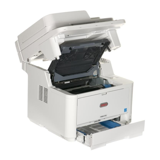
1. CONFIGURATION Oki Data CONFIDENTIAL 1.2 Structure of MFP The insides of multi function printers are composed of the following parts. • Scanner part • Electronic photography process part • Paper path • Control part (CU part/PU part) • Power supply parts (high voltage part/low voltage part) Figure 1-2 shows the composition of the MFP . -
Page 10: Offer Of Options
1. CONFIGURATION Oki Data CONFIDENTIAL 1.3 Offer of Options This product can be installed with the following option. Second Tray Unit 45762101TH Rev.1... -
Page 11: Specifications
1. CONFIGURATION Oki Data CONFIDENTIAL 1.4 Specifications Print specifications Item MB472dnw Paper Paper 1st Tray A4,A5,A6,B5,Letter,Legal13/13.5/14,Executive, Item MB472dnw input size Statement,16K (197 x 273),16K (195 x 270), Segment 16K (184 x 260),Custom Print speed 33ppm 2nd Tray A4,A5,B5,Letter,Legal13/13.5/14,Executive, (simplex) (Option) - Page 12 1. CONFIGURATION Oki Data CONFIDENTIAL Item MB472dnw Item MB472dnw Paper Paper Facedown A4,A5,A6,B5,Letter,Legal13/13.5/14,Executive, Operation panel Switches Copy, Scan, Print, Fax, Status, Setting, Help, output size Tray 16K (197 x 273),16K (195 x 270), Reset, Back, OK, Arrow(Up/Down/Left/Right), 16K (184 x 260),Statement,Custom...
-
Page 13: Copy Specifications
1. CONFIGURATION Oki Data CONFIDENTIAL Copy specifications Item MB472dnw Print Function Quiet mode Item MB472dnw Toner save Copy speed up to 33cpm mode (Flatbed) Override A4/ Yes (for Printing) Letter up to 35cpm Letter Copy speed up to 33cpm AirPrint... -
Page 14: Scan Specifications
1. CONFIGURATION Oki Data CONFIDENTIAL Scan specifications Item MB472dnw Copy function Duplex copy Yes (1 to 2, 2 to 1, 2 to 2) Item MB472dnw ID card copy Sensor type Color CIS Collate Optical 600dpi Continuous resolution scan Scan speed... -
Page 15: Fax Specifications
1. CONFIGURATION Oki Data CONFIDENTIAL FAX specifications Common specifications Item MB472dw Item MB472dw Connetivity PSTN, PBX line Emulation PCL / SIDM / XPS Speed ITU-T G3 (Super G3) up to 33.6kbps, Approx. Network (wired) 10/100/Gigabit 2seconds/page Network (wireless) 802.11a/b/g/n (standard) -
Page 16: Report Print
1. CONFIGURATION Oki Data CONFIDENTIAL Report Print Manual Report Name Auto Op Panel Manual E-mail/Internet FAX Report Name Auto Op Panel Transmit Confirmation Configuration Report File List E-mail/Internet FAX Error Log Check Message Report Demo Page 28 Network Syslog Print... -
Page 17: Interface Specifications
1. CONFIGURATION Oki Data CONFIDENTIAL 1.5 Interface specifications 1.5.1 USB Interface Specification (2) Cable Cable length : Specification Cable of USB2.0 spec. of less than 5m.(less 1.5.1.1 Outline of USB Interface than 2m is recommended) (1) Basic Specification 1.5.1.3 USB Interface Signal... -
Page 18: Network Interface Specification
1. CONFIGURATION Oki Data CONFIDENTIAL 1.5.2 Network Interface Specification 1.5.2.3 Network Interface Signal Pin No. Signal name Functions 1.5.2.1 Network Interface Basic Specification TRD+(0) Transmit and receive Data 0 (+) TRD-(0) Transmit and receive Data 0 (-) Network Protocol ・TCP/IP related... -
Page 19: Telephone Line Interface Specification
1. CONFIGURATION Oki Data CONFIDENTIAL 1.5.3 Telephone Line Interface Specification 1.5.4 USB Host Interface 1.5.3.1 Outline of telephone Line Interface 1.5.4.1 Outline of USB Host Interface The machine will reliably communicate with distant stations over voice-level telephone line. (1) Basic Specification 1.5.3.2 Telephone Line Interface Connector and Cable... -
Page 20: Wireless Lan Interface
1. CONFIGURATION Oki Data CONFIDENTIAL 1.5.5 Wireless LAN Interface 1.5.5.1 Outline of Wireless LAN (1) Specification IEEE 802.11b/g/n (2.4GHz/5GHz) (2) Power supply voltage (3) MFP side interfaces USB Port Note! In using wireless LAN, don't connect a LAN cable to this product. -
Page 21: Troubleshooting Procedures
Oki Data CONFIDENTIAL TROUBLESHOOTING PROCEDURES 2.1 Precautions prior to repair ............2-2 2.2 Items to be checked prior to taking action on abnormal images ..2-2 2.3 Precautions when taking action on abnormal images ....2-2 2.4 Preparations for troubleshooting ...........2-2 2.5 Troubleshooting method ...............2-3... -
Page 22: Precautions Prior To Repair
2. TROUBLESHOOTING PROCEDURES Oki Data CONFIDENTIAL 2.1 Precautions prior to repair (1) Confirm the basic check items indicated in the User's Manual. (2) Through hearing from the user, obtain information, as far in detail as possible, on the situation concerning the fault. -
Page 23: Troubleshooting Method
2. TROUBLESHOOTING PROCEDURES Oki Data CONFIDENTIAL 2.5 Troubleshooting method 2.5.1 LCD messages list If a trouble occurs in the printer, search for it by the following procedure: Problem Initializing & Shutdown generated No. Category Status Error Warning Description Code Problem is displayed... - Page 24 2. TROUBLESHOOTING PROCEDURES Oki Data CONFIDENTIAL Normal No. Category Status Error Warning Description No. Category Status Error Warning Description Code Code Initializing %STORAGE% Error: %ERRCODE% %ERRCODE% : 0 Normal 40988 PU downloading ... Downloading PU F/W (This is To %STORAGE%...
- Page 25 2. TROUBLESHOOTING PROCEDURES Oki Data CONFIDENTIAL No. Category Status Error Warning Description No. Category Status Error Warning Description Code Code Normal 40828 Please check data. Indicates that writing of Normal Please check data. Indicates that an error has Message Data Write Error...
- Page 26 2. TROUBLESHOOTING PROCEDURES Oki Data CONFIDENTIAL No. Category Status Error Warning Description No. Category Status Error Warning Description Code Code Normal 10002 <Print Stand-by Screen> Shows Offline status. Normal 10017 Demo Page printing ... Printing Demo Pages. Indicates that the stored...
- Page 27 2. TROUBLESHOOTING PROCEDURES Oki Data CONFIDENTIAL No. Category Status Error Warning Description No. Category Status Error Warning Description Code Code Normal 10889 Scan To Log printing ... Printing Scan to Log. Normal 10099 Print page %PAGES% No. of Copy printing.
- Page 28 2. TROUBLESHOOTING PROCEDURES Oki Data CONFIDENTIAL No. Category Status Error Warning Description No. Category Status Error Warning Description Code Code Normal 10007 Deleting data. Indicates a job being Normal 10863 <ScanToUSBMemory> %LOCATION_INFO%: cancelled due to no Location Information (Scan To Scanning ...
- Page 29 2. TROUBLESHOOTING PROCEDURES Oki Data CONFIDENTIAL No. Category Status Error Warning Description No. Category Status Error Warning Description Code Code Normal <ScanToPrintAP> Indicates that it is copying. Normal 10859 Data writing to USB Memory. Indicates that it is wrighting Scan Pages sss...
- Page 30 2. TROUBLESHOOTING PROCEDURES Oki Data CONFIDENTIAL No. Category Status Error Warning Description No. Category Status Error Warning Description Code Code Normal Fax receiving ... Indicates that it is receiving Normal Fax sending ... Indicates that it is sending fax fax data.
- Page 31 2. TROUBLESHOOTING PROCEDURES Oki Data CONFIDENTIAL No. Category Status Error Warning Description No. Category Status Error Warning Description Code Code Normal Cancelling ... Indicates that the scanning for Normal 10875 Cancelling sending ... Indicates that E-mail sending fax sending is cancelling by is cancelling.
- Page 32 2. TROUBLESHOOTING PROCEDURES Oki Data CONFIDENTIAL No. Category Status Error Warning Description No. Category Status Error Warning Description Code Code Normal 10801 Group List printing ... Indicates that printing of fax Normal 10810 Fcode Box List printing ... Indicates that printing of the location list that is registered enabled F code box list.
- Page 33 2. TROUBLESHOOTING PROCEDURES Oki Data CONFIDENTIAL No. Category Status Error Warning Description No. Category Status Error Warning Description Code Code Normal Do you wish to resume scanning? Indicates to resume the Normal 10766 Transmit/Receipt Journal printing ... Indicates that printing of ADF scanning for copy.
- Page 34 2. TROUBLESHOOTING PROCEDURES Oki Data CONFIDENTIAL Warning PJL Status Category Error Warning Description Code PJL Status Category Error Warning Description Code Warning 10076 (K) Image Drum Unit Near Life The life of the drum (warning). Displayed in Warning 10081 (K) %COLOR% Toner Low Toner amount is low.
- Page 35 2. TROUBLESHOOTING PROCEDURES Oki Data CONFIDENTIAL PJL Status PJL Status Category Error Warning Description Category Error Warning Description Code Code Warning 10944 (K) %COLOR% Head Data Error The LED head calibration Warning 32000 Disk Use Failed %FS_ERR% A disk error is occurred, data is missing or invalid.
- Page 36 2. TROUBLESHOOTING PROCEDURES Oki Data CONFIDENTIAL PJL Status PJL Status Category Error Warning Description Category Error Warning Description Code Code Warning 32026 File System is write protected. An attempt to write in Warning 10756 Wait Timeout is disabled. Indicates that Print...
- Page 37 2. TROUBLESHOOTING PROCEDURES Oki Data CONFIDENTIAL PJL Status PJL Status Category Error Warning Description Category Error Warning Description Code Code Warning 10823 Access Limitation Error Notifies users that jobs Warning 10818 Job Log Writing Error The log is not registered...
- Page 38 2. TROUBLESHOOTING PROCEDURES Oki Data CONFIDENTIAL PJL Status Category Error Warning Description Code E-mail receiving has been Indicates that Email Warning cancelled. receiving has been canceled. It has the following Please see Help for details. possibilities. Close - The format of email that has received is illegal or not supported.
- Page 39 2. TROUBLESHOOTING PROCEDURES Oki Data CONFIDENTIAL Error (Enable to restore) PJL Status Error Warning Description Category Code PJL Status Error Warning Description Category Code Error 40947 (K) %COLOR% Non Recommended It is a toner besides our Toner.: %ERRCODE% specification. Error...
- Page 40 2. TROUBLESHOOTING PROCEDURES Oki Data CONFIDENTIAL PJL Status PJL Status Error Warning Description Error Warning Description Category Category Code Code Error 40959 (K) Please check %COLOR% Toner Something is wrong with Error 40054 Paper Jam: 372 Jam has occurred nearby Cartridge.: %ERRCODE%...
- Page 41 2. TROUBLESHOOTING PROCEDURES Oki Data CONFIDENTIAL PJL Status PJL Status Error Warning Description Error Warning Description Category Category Code Code Error 40033 (K) Please check Image Drum Unit. The image drum is not Error 40789 Document Jam Indicates that the correctly installed.
- Page 42 2. TROUBLESHOOTING PROCEDURES Oki Data CONFIDENTIAL PJL Status PJL Status Error Warning Description Error Warning Description Category Category Code Code Error 30941 USB Memory disconnected. Indicates that the USB Error 30938 Decode error occurred. Indicates that an error has memory was extracted.
- Page 43 2. TROUBLESHOOTING PROCEDURES Oki Data CONFIDENTIAL PJL Status PJL Status Error Warning Description Error Warning Description Category Category Code Code Error 40593 File Transmission Error Indicates that file sending Error 40812 Getting target IP failed. Indicates that DHCP was failed due to the file Please check DHCP settings.
- Page 44 2. TROUBLESHOOTING PROCEDURES Oki Data CONFIDENTIAL PJL Status PJL Status Error Warning Description Error Warning Description Category Category Code Code Error 40587 Please install new Image Drum Unit The life of the image drum Error 482yy Tray Media Mismatch: The size of paper or...
- Page 45 2. TROUBLESHOOTING PROCEDURES Oki Data CONFIDENTIAL PJL Status PJL Status Error Warning Description Error Warning Description Category Category Code Code Error 40735 Memory Overflow Indicates that Memory Error 40592 Not authorized to write file. Indicates that failed to Overflow is occurred...
- Page 46 2. TROUBLESHOOTING PROCEDURES Oki Data CONFIDENTIAL PJL Status Error Warning Description Category Code Error Memory Overflow Memory overflow has occurred while fax is being received. Close Error Telephone The screen that specified talking by telephone is displayed, when the handset hooked up.
- Page 47 2. TROUBLESHOOTING PROCEDURES Oki Data CONFIDENTIAL Error (Disable to restore) PJL Status Error Warning Description Category Code PJL Status Error Warning Description Category Code Error Inspection is required. Displays that PU Communication Error communication to PU Error 40700 Inspection is required.
- Page 48 2. TROUBLESHOOTING PROCEDURES Oki Data CONFIDENTIAL PJL Status PJL Status Error Warning Description Error Warning Description Category Category Code Code Error 40057 Inspection is required. A fatal error occurred. Error 40057 Power OFF/ON A fatal error occurred. %ERRCODE%:Error %CODE% For more information, see...
- Page 49 2. TROUBLESHOOTING PROCEDURES Oki Data CONFIDENTIAL PJL Status Error Warning Description Category Code Error 40057 Power OFF/ON Downloading Media Table %ERRCODE%:Download Error to PU has failed. (Related to CustomMediaType.) %ERRCODE%: specifies 3 digits (decimal) error code. The message of fatal error is specifiedby English only.
-
Page 50: Service Call List
2. TROUBLESHOOTING PROCEDURES Oki Data CONFIDENTIAL 2.5.2 Service Call List Display Cause Error details Measure Power OFF/ON Video error. Is the CU/PU board installed Reinstall it properly. 073 : Error ** An error was properly? Change the PC to a... - Page 51 2. TROUBLESHOOTING PROCEDURES Oki Data CONFIDENTIAL Display Cause Error details Measure Display Cause Error details Measure Inspection is Engine control Turn off and on the Inspection is LED head Is the LED head installed Install the LED head required. logic error required.
- Page 52 2. TROUBLESHOOTING PROCEDURES Oki Data CONFIDENTIAL Display Cause Error details Measure Display Cause Error details Measure Inspection is Option unit I/F Turn off and on the Inspection is Secure Disk required. error MFP. required. Erasing Error 182 : Error Does the error occur again?
-
Page 53: Fax Error List
2. TROUBLESHOOTING PROCEDURES Oki Data CONFIDENTIAL 2.5.3 Fax Error List Value Description (Hex) Termination Code List Phase-B Command Rec Error (Failed to receive a control signal at the time of receiving) (Including SEP discrepancy in bulletin board polling receiving) Value... -
Page 54: Email/Internet Fax/Fax Server Error List
2. TROUBLESHOOTING PROCEDURES Oki Data CONFIDENTIAL 2.5.4 Email/Internet FAX/FAX Server Error List ErrorCode Description Connection failed. Please check "SMTP Server" settings. Connection failed. Please check "SMTP Server Port" settings. Authentication failed. "SMTP Auth" Unsupported. Authentication failed. "SMTP Auth" Login failed. Be sure of the login name and password for the mail server. -
Page 55: Preparing For Troubleshooting
.............2-57 (1-1) LCD displays nothing ................2-36 (10-2) All fans of the printer do not rotate............2-57 (1-2) Display of OKI logo ................2-37 (11) Print speed is slow. (Performance is low.) ...........2-57 (1-3) Error message display .................2-37 (11-1) Print speed decreases. - Page 56 2. TROUBLESHOOTING PROCEDURES Oki Data CONFIDENTIAL 2.5.5.(1) LCD Display Trouble Check item Checking Action in case of fail (1-1) LCD displays nothing (1-1-2) Checking connections Connection between SU Make sure the 16-pin FFC Connect the cable Check item Checking Action in case of fail...
- Page 57 2. TROUBLESHOOTING PROCEDURES Oki Data CONFIDENTIAL (1-2) Display of OKI logo 2.5.5.(2) Abnormal MFP operation after powered on (2-1) No operation Check item Checking Action in case of fail Check item Checking Action in case of fail (1-2-1) Operation panel display does not change.
- Page 58 2. TROUBLESHOOTING PROCEDURES Oki Data CONFIDENTIAL Check item Checking Action in case of fail Check item Checking Action in case of fail (2-1-2) Confirmation of the power switch LED (2-1-3) Checking connections Power Switch LED Confirm whether the LED is off.
- Page 59 2. TROUBLESHOOTING PROCEDURES Oki Data CONFIDENTIAL (2-2) Abnormal sound Check item Checking Action in case of fail Check item Checking Action in case of fail (2-2-4) Checking cable wiring Cable wiring around cooling Check whether a cable touches Lay the cable properly.
- Page 60 2. TROUBLESHOOTING PROCEDURES Oki Data CONFIDENTIAL (2-3) Abnormal odor Confirmation Items Confirmation Tasks Action at NG (2-3-1) Locate the position with abnormal odor occurred. Fuser unit Take out the fuser and confirm Perform (2-3-2). the odor. Low-voltage power supply Take out the low-voltage power...
-
Page 61: Paper Jams
2. TROUBLESHOOTING PROCEDURES Oki Data CONFIDENTIAL Paper Jams Clearing Paper Jams This section explains how to clear paper jams. Caution Possible to get burned. Reference! • For details on the location of each component of the machine, refer to "Swich scan test" on P . 3-16 and "Motor clutch test" on P .3-18. - Page 62 2. TROUBLESHOOTING PROCEDURES Oki Data CONFIDENTIAL (5) Then, remove the Duplex unit ② by raising the coloured handles ③ on each side, Error Code 372 (Duplex paper jam) and then by holding the handles and gently lifting it out. (1) Remove any documents from the document tray if any.
- Page 63 2. TROUBLESHOOTING PROCEDURES Oki Data CONFIDENTIAL (7) When you return the transcription unit into the printer, insert both projections ④ of (9) Secure the transcription unit to the printer by rotating both handles of the the front end of transcription unit into holders of the printer.
- Page 64 2. TROUBLESHOOTING PROCEDURES Oki Data CONFIDENTIAL Error Code 380, 381, 382, 389 (Paper feed jam) (5) If the top end of paper is visible at the rear side of transparent resist guide, rotate the resist guide toward the fuser unit and hold the paper top end and carefully pull (1) Remove any documents from the document tray if any.
- Page 65 2. TROUBLESHOOTING PROCEDURES Oki Data CONFIDENTIAL If the bottom end of paper is visible, hold the paper by your hands and carefully pull • If the bottom end of paper is not visible but its top end is visible at the paper out the paper.
- Page 66 2. TROUBLESHOOTING PROCEDURES Oki Data CONFIDENTIAL • If you have failed to remove jammed paper, do not force to pull out the paper Error Code 390 (Paper feed jam (Multipurpose tray)) but follow the steps below. (1) Remove any documents from the document tray if any.
- Page 67 2. TROUBLESHOOTING PROCEDURES Oki Data CONFIDENTIAL If neither the top or bottom end of paper is visible, move the jammed paper in the (6) Re-install the image drum complete with toner cartridge, ensuring that the pegs arrow direction as shown. Hold the top end of paper by your hands and carefully (1 &...
- Page 68 2. TROUBLESHOOTING PROCEDURES Oki Data CONFIDENTIAL Error Code 391, 392 (Paper feed jam) (3) Return the tray into the machine. (4) Open the scanner unit. Error Code 391 indicates an error in Tray1 and Error Code 392 indicates a paper jam in (5) Press the top cover open button ①...
- Page 69 2. TROUBLESHOOTING PROCEDURES Oki Data CONFIDENTIAL Document Jam Occurred (3) Hold jammed document by the top edge, and gently pull it out. When you can see the document In the Duplex Paper Path (1) Open the ADF cover, and pull out the document upward.
- Page 70 2. TROUBLESHOOTING PROCEDURES Oki Data CONFIDENTIAL If the edge of the document cannot be seen in the ADF, lift the document tray ② and then pull out the document. ② Pull down the document tray. (4) Close the ADF cover.
- Page 71 2. TROUBLESHOOTING PROCEDURES Oki Data CONFIDENTIAL 2.5.5. (3) Paper feed jam (Error code 391: 1st tray) Check item Check operation Actions for NG (3-1) Does a jam error occur when turning on the power? results (3-2-3) Check the paper feed roller rotate.
- Page 72 2. TROUBLESHOOTING PROCEDURES Oki Data CONFIDENTIAL 2.5.5. (4) Feed jam (Error code: 380, 381) (4-2) Jam occurs immediately after the paper feed is started. (4-1) Jam occurs immediately after the power is turned on. Check item Check operation Actions for NG...
- Page 73 2. TROUBLESHOOTING PROCEDURES Oki Data CONFIDENTIAL 2.5.5. (5) Paper feed jam (Error code 390: Multipurpose tray) Check item Check operation Actions for NG (5-1) Does a jam error occur when turning on the power? results (4-2-2) Check condition of the mechanical parts...
- Page 74 2. TROUBLESHOOTING PROCEDURES Oki Data CONFIDENTIAL (5-2) Jam occurs immediately after paper feed is started. (Multipurpose tray) Check item Check operation Actions for NG results Check item Check operation Actions for NG (5-2-3) Check the paper feed roller rotate. results...
- Page 75 2. TROUBLESHOOTING PROCEDURES Oki Data CONFIDENTIAL 2.5.5. (6) Paper running jam (Error code: 381) 2.5.5. (7) Two-sided printing jam (Error code: 372) (7-1) Two-sided printing jam. (6-1) Jam occurs immediately after the power is turned on. Check item Check operation...
- Page 76 2. TROUBLESHOOTING PROCEDURES Oki Data CONFIDENTIAL 2.5.5. (8) Paper size error (Error code: 400) 2.5.5. (9) Fuser unit error (Error code: 170 to 177) (9-1) Error occurs immediately after the power is turned on. (8-1) Jam occurs when paper end is located near the entrance sensor.
- Page 77 2. TROUBLESHOOTING PROCEDURES Oki Data CONFIDENTIAL 2.5.5. (10) Motor fan error (Error code: 122, 127, 128) 2.5.5. (11) Print speed is slow. (Performance is low.) (10-1) The low voltage power supply fan does not rotate immediately after the power is (11-1) Print speed decreases.
- Page 78 2. TROUBLESHOOTING PROCEDURES Oki Data CONFIDENTIAL 2.5.5. (12) Option unit cannot be recognized. 2.5.5. (13) LED head cannot be recognized. (Error code: 134) (12-1) Option try unit cannot be recognized. (13-1) Service call 134 (LED HEAD Missing) Check item Check operation...
- Page 79 2. TROUBLESHOOTING PROCEDURES Oki Data CONFIDENTIAL 2.5.5. (14) Toner cartridge cannot be recognized. (Error code: 543) (1) How to check operation of the toner sensor at the printer side. Status change of the toner sensor can be checked from the Operator Panel (14-1) Error caused by the consumable items.
- Page 80 2. TROUBLESHOOTING PROCEDURES Oki Data CONFIDENTIAL (14-3) Error caused by the defective mechanism 2.5.5. (15) Fuse cut error (Error code: 153 to 155) (15-1) Fuse cut error Check item Check operation Actions for NG results Check item Check operation Actions for NG...
- Page 81 2. TROUBLESHOOTING PROCEDURES Oki Data CONFIDENTIAL 2.5.5. (16) Humidity sensor error (Error code: 123) (16-1) Humidity sensor error Check item Check operation Actions for NG results (16-1-1) Check the system connection Connection to the Check if the 28-conductor FFC is connected to...
-
Page 82: Print Troubleshooting
2. TROUBLESHOOTING PROCEDURES Oki Data CONFIDENTIAL 2.5.6 Print Troubleshooting Pale printing or the whole printing is faded. • Does the printer lack toner? (Is the message of Toner Low displayed?) The troubleshooting procedure of abnormal printing is described as follows. The typical •... - Page 83 2. TROUBLESHOOTING PROCEDURES Oki Data CONFIDENTIAL The white section is dirty Vertical black belt/ Black line • Is the image drum exposed by the external light? • Clean the LED lens array of the LED head. • Yes Install the image drum in the printer and wait 30 minutes.
- Page 84 2. TROUBLESHOOTING PROCEDURES Oki Data CONFIDENTIAL In case of error printing Vertical white belt/ White line • Is the LED lens dirty? • Does the contact plate of the transfer roller contact the TR terminal of the high- • Yes Clean the LED lens.
- Page 85 2. TROUBLESHOOTING PROCEDURES Oki Data CONFIDENTIAL Transfer roller Frame-Assy-TR Fuse Contact plate for transfer High voltage power supply board TR terminal Fuse Contact plate for transfer Figure 2-2 Figure 2-3 2-65 45762101TH Rev.1...
- Page 86 2. TROUBLESHOOTING PROCEDURES Oki Data CONFIDENTIAL Fuser Assy Contact plate Figure 2-4 2-66 45762101TH Rev.1...
-
Page 87: Response After Flash Compulsive Initialization
2. TROUBLESHOOTING PROCEDURES Oki Data CONFIDENTIAL 2.5.7 Response after Flash compulsive initialization 2.5.8 Copy Image Abnormality Error Troubleshooting • When the following symptom occurs in the copy image, implement the inspection and Explain the response after compulsive initialization is performed with trouble occurred in adjustment of the copy image. -
Page 88: Network Troubleshooting
Subnet mask, Gateway response is correct. address correctly. (4) Check the utility Check the settings of OKI Check the setting items of OKI Set the setting items of LPR utility. LPR utility. OKI LPR utility correctly. (5) Check the OS standard port. -
Page 89: Wireless Troubleshooting
2. TROUBLESHOOTING PROCEDURES Oki Data CONFIDENTIAL 2.5.10 Wireless Troubleshooting *1 : Check once again whether the SSID, security setting, and an encrypting key of the wireless LAN access point are same as the settings of this device. When any one of settings is different, the device cannot be connected to the wireless LAN access point. -
Page 90: Fuse Checking
2. TROUBLESHOOTING PROCEDURES Oki Data CONFIDENTIAL 2.6 Fuse Checking Table 7-6 Fuse Errors Fuse Name Error Description Insert Point Resistance Fuse Name Error Description Insert Point Resistance SU board Service Call "Lamp 1Ω or less (MSU) Error Please call CU/PU board... -
Page 91: Maintenance Menus
Oki Data CONFIDENTIAL MAINTENANCE MENUS MB461/MB471/MB491 can be adjusted by using Maintenance Utility, or button operation on its operator panel. The printer has maintenance menus in addition to general menus. The menus intended for adjustment purposes should be selected. 3.1 Maintenance Menu ...............3-2 3.2 Service Bit Menu ................3-9... -
Page 92: Maintenance Menu
"However, operation when JP1/JPOEM/OEMA/OEML is chosen is not guaranteed. The display condition of the menu is following two. ① "System Maintenance" - "When "OKIUSER" is other than JPOEM1, OEMA or OEML ② "Manufacturer" is "OKI DATA CORP". Format Flash Execute Formats flash ROM memory. - Page 93 3. MAINTENANCE MENUS Oki Data CONFIDENTIAL Default Default Default Item1 Item2 Item3 Item4 Item5 Value value value value Notes Password System Test Print Enable Switches between displaying and not displaying the "ID Check" and "Engine Maintenance Menu Disable Information" in the "Report" - "Print Report" category (default: DISABLE). If this item is set to "DISABLE,"...
- Page 94 3. MAINTENANCE MENUS Oki Data CONFIDENTIAL Default Default Default Item1 Item2 Item3 Item4 Item5 Value value value value Notes Password Panel Sound Test Select the volume of the forced buzzer. Maintenance Middle For the buzzer pattern, use the error sound (three buzzes)
- Page 95 3. MAINTENANCE MENUS Oki Data CONFIDENTIAL Default Default Default Item1 Item2 Item3 Item4 Item5 Value value value value Notes Password Scanner Adjust Mech. Adjust FB FB Drive 10 ~ 1400 [mA] 300 [mA] 300 [mA] Only for engineering test Maintenance...
- Page 96 3. MAINTENANCE MENUS Oki Data CONFIDENTIAL Default Default Default Item1 Item2 Item3 Item4 Item5 Value value value value Notes Password Scanner Adjust CIS Set CIS 0 ~ 4294967295 Only for engineering test Maintenance Exposure Change LED exposure time settings, and then read the document using time PC Scan.
- Page 97 3. MAINTENANCE MENUS Oki Data CONFIDENTIAL Default Default Default Item1 Item2 Item3 Item4 Item5 Value value value value Notes Password Scanner Mechanical FBS Test Speed Mono 300 x 600dpi Conduct mechanical testing (without reading an image). Maintenance Test Mono 600 x 600dpi...
- Page 98 3. MAINTENANCE MENUS Oki Data CONFIDENTIAL Default Default Default Item1 Item2 Item3 Item4 Item5 Value value value value Notes Password Line Test Tone Send 2100Hz Tone send test conducted. Maintenance Test 1850Hz 1650Hz 1100Hz DP Send 0 ~ 9 Key DP send test conducted.
-
Page 99: Service Bit Menu
3. MAINTENANCE MENUS Oki Data CONFIDENTIAL 3.2 Service Bit Menu Additional Fax Setting menu Item Settings Description (When setup ServiceBit=ON, the following items will be displayed at Admin Setup→Fax Calling Timer 1~255 second Sets the call connection wait Depends on Country time (TO timer). -
Page 100: Maintenance Utility
3. MAINTENANCE MENUS Oki Data CONFIDENTIAL 3.3 Maintenance Utility 3.3.1 Maintenance Utility Section in Operation from Maintenance operator panel Option Adjustment Utility (section in this The adjustments described in table 3-1 should be made by using Maintenance Utility. Operating maintenance... -
Page 101: Self-Diagnostic Mode
3. MAINTENANCE MENUS Oki Data CONFIDENTIAL 3.4 Self-diagnostic mode This section describes LEVEL 0 and LEVEL 1. (1) Menu option switching Self-diagnostic Only while displayed as shown in a shaded area ( XXXXX mode layout (entire) 3.4.1 Operator Panel the level of the self-diagnostic mode can be switched. [2] or [8] is used to switch to the option in a non-shaded area ( XXXXX ). - Page 102 3. MAINTENANCE MENUS Oki Data CONFIDENTIAL (1) How to select the menu items XXXX Menu items can be selected by pressing of [4] or [ ], or by pressing of [2] or [8]. LEVEL0 XXXX Menu items can be entered by pressing of [6] or [4], and can be selected by pressing of [2] or [8].
- Page 103 3. MAINTENANCE MENUS Oki Data CONFIDENTIAL (1) How to select the menu items Menu items can be selected by pressing either [2] or [8] key, and executed by pressing [6]. LEVEL1 XXXXX Menu items can be entered by pressing of [6] or [ ], and can be selected by pressing of [2] or [8].
-
Page 104: Ordinary Self-Diagnostic Mode (Level 1)
3. MAINTENANCE MENUS Oki Data CONFIDENTIAL 3.4.2 Ordinary self-diagnostic mode (level 1) 3.4.2.1 Entering self-diagnostic mode (level 1) 1. Make sure that the LCD is in standby state (no Error window is shown) and Menu items of the ordinary self-diagnostic mode are shown below. -
Page 105: Switch Scan Test
3. MAINTENANCE MENUS Oki Data CONFIDENTIAL 3.4.2.3 Switch scan test This self-diagnostic menu is used to check the entry sensor and the switch. ] or Enter the self-diagnostic mode (level 1), press the [2 key repeatedly ,and Face down stacker... - Page 106 3. MAINTENANCE MENUS Oki Data CONFIDENTIAL Table 3-3 SWITCH SCAN details <Item having no function> Asterisk mark (*) is displayed in the lower row of display area. * 1: “L” is displayed when the cover is opened. Display area, Display...
-
Page 107: Motor Clutch Test
3. MAINTENANCE MENUS Oki Data CONFIDENTIAL 3.4.2.4 Motor clutch test This self-diagnostic menu is used to test the motor and clutch. ] or 1. Enter the self-diagnostic mode (level 1), press the [2 key repeatedly ,and Registration roller 2nd eject roller press the [6] key when the "MOTOR &... - Page 108 3. MAINTENANCE MENUS Oki Data CONFIDENTIAL Table 3-4 Unit name display Drive restriction condition Remarks MAIN MOTOR EXIT MOTOR FWD FaceUp Cover close EXIT MOTOR REV FaceUp Cover open REGIST CLUTCH MAIN MOTOR driving T1 HOP CLUTCH MAIN MOTOR driving...
-
Page 109: Test Print
3. MAINTENANCE MENUS Oki Data CONFIDENTIAL 3.4.2.5 Test print Display Setting Function value This self-diagnostic menu is used to print the test pattern that is built inside PU. Other test PRINT EXECUTE – Pressing the [6] key starts print/Pressing the patterns are stored in the controller. - Page 110 3. MAINTENANCE MENUS Oki Data CONFIDENTIAL While the message "PRINT EXECUTE" that is set by the operation specified in step Print pattern (It cannot be used for checking PQ.) 2 is being displayed, press the [6] key and the test print is executed with the setting 0:Write paper print value that has been set by steps 2 and 3.
- Page 111 3. MAINTENANCE MENUS Oki Data CONFIDENTIAL • Displays are switched by pressing the [2] key. • Displays are switched by pressing the [2] key. KR=*.** TROFF:** KR : BLACK transfer roller resistance value [unit: uA] TROFF : Transfer OFF voltage setting table ID number [unit: HEX] Repeat steps 2 to 4 as required.
-
Page 112: Consumable Item Counter Display
3. MAINTENANCE MENUS Oki Data CONFIDENTIAL 3.4.2.6 Consumable item counter display 3.4.2.7 Number of print copies counter display This self-diagnostic menu is used to display the consumption status of the consumable items. This self-diagnostic menu is used to display status of the number of copies of a printer. -
Page 113: Switching Between The Factory Mode And The Shipping Mode
3. MAINTENANCE MENUS Oki Data CONFIDENTIAL 3.4.2.8 Switching between the Factory mode and the Shipping mode 3.4.2.9 Self-diagnostic function setting This self-diagnostic menu item is used to switch between the Factory mode and the Shipping This self-diagnostic menu is used to set valid/invalid of the error detection by the various mode. -
Page 114: Led Head Serial Number Display
3. MAINTENANCE MENUS Oki Data CONFIDENTIAL 3.4.2.10 LED head serial number display Operation at the Display Setting value Function setting value This self-diagnostic menu item is used to check whether the downloaded LED head data TONER SENSOR ENABLE Detects Valid/Invalid of toner sensor matches the serial number of the actual LED head. -
Page 115: Adjustment At Part Replacement
3. MAINTENANCE MENUS Oki Data CONFIDENTIAL 3.4.3 Adjustment at part replacement Adjustment is necessary while replacing the following part. Replacing part Adjustment Main PCB board EEPROM data upload / download 3.4.3.1 EEPROM data upload / download method In the case of replacing the Print Board of Controller, copy the old EEPROM content to the new EEPROM of new board and then save the customer setting. -
Page 116: Switch Pressing Function When Power Supply Is Turned On
3. MAINTENANCE MENUS Oki Data CONFIDENTIAL 3.5 Switch pressing function when power supply is turned on When power supply of printer is turned on, the functions of usable switches are as follows. And, the switches below are effective when pressed before LED is lighted in the special start confirming pattern. -
Page 117: Settings After Parts Replacement
3. MAINTENANCE MENUS Oki Data CONFIDENTIAL 3.6 Settings after Parts Replacement The necessary adjustments after the parts exchange are explained as follows. Configure CU-block serial number information (Refer to Maintenance Utility Operating Manual, about Serial number setting) when the setting information... - Page 118 3. MAINTENANCE MENUS Oki Data CONFIDENTIAL • If you want to specify the PU serial number, please add a "0" (a • On the menu of [Serial number setting], set the [Select printer normal-width zero) then input the 11-digit number. (Please notice serial number] to [CU serial number] and [Display mode] to [Display that when read out, the number will be 10 digits.)
- Page 119 3. MAINTENANCE MENUS Oki Data CONFIDENTIAL (2) [When not facing OEL] (2-2) Set the CU serial number CU serial numbe setting is unnecessary When not facing OEL. (2-1) Set the PU serial number (Refer to Maintenance utility operation manual, about Serial number (3) Change to Shipping mode (Refer to Maintenance Utility Operating Manual setting) SAP serial number can be applied to the device.
- Page 120 3. MAINTENANCE MENUS Oki Data CONFIDENTIAL 3.6.2 Notes on SU board (MSU)/Scanner Unit replacement 1. Set the Scanner parameter when replacing the SU board (MSU)/Scanner Unit : Before replacing the SU board (MSU)/Scanner Unit, try to get the scanner setting parameters from the board by using the Board Replacement function of Maintenance Utility, if it is still able to be accessed by Maintenance Utility.
-
Page 121: Replacement Of Parts
Oki Data CONFIDENTIAL REPLACEMENT OF PARTS This chapter describes the procedures of the field replacement of parts, assemblies and units. The procedures are to detach them. Reverse the procedures to attach them. The reference part numbers used in this manual (such as ) do not identical to the part numbers in the maintenance disassembly configuration diagram (45762101TL) and RSPL (45762101TR) for the manual. -
Page 122: Notes On Replacement Of Parts
4.REPLACEMENT OF PARTS Oki Data CONFIDENTIAL 4.1 Notes on replacement of parts (1) Prior to replacing a part, unplug the AC cord and the interface cable. (2) Do not disassemble the printer so long as it operates properly. (a) Be sure to use the following procedure to unplug the AC cord: (3) Minimize disassembly. -
Page 123: Maintenance Tools
4.REPLACEMENT OF PARTS Oki Data CONFIDENTIAL Maintenance Tools: Table 4-1-2 shows the tools necessary to use Maintenance Utility software. Table 4-1-1 shows the tools necessary to replace printed-circuit boards and units: Table 4-1-2: Maintenance Tools Maintenance Tool Quantity Remarks Table 4-1-1: Maintenance Tools... -
Page 124: Part Replacement Procedure
4.REPLACEMENT OF PARTS Oki Data CONFIDENTIAL 4.2 Part replacement procedure This section describes the procedure for replacing the parts and assemblies shown in the disassembly diagrams below. 4.2.1 Cover Side (L) (1) Remove the cassette assembly. (2) Open the Scanner, Cover-Assy-Stacker, Frame-Assy-MPT and Cover- Assy-Rear. - Page 125 4.REPLACEMENT OF PARTS Oki Data CONFIDENTIAL 4.2.2 Cover Side(R) (1) Remove the cassette assembly. (2) Open the Scanner, the Cover-Assy-Stacker, the Frame-Assy-MPT and the Cover-Assy-Rear. (3) Remove the Screw (Black) ① and the Screw (Silver) ② . (4) Unlatch the claws (7points) with to pull the front side of the mainbody to the arrow in figure to detach the Cover-Side (R) ③...
- Page 126 4.REPLACEMENT OF PARTS Oki Data CONFIDENTIAL (3) Disconnect all cables and remove four Screws (Silver) ④ to detach the 4.2.3 Board MRM Board MRM ③ . (1) Remove the Cover Side (R). (Refer to 4.2.2) (2) Remove four Screws (Silver) ① , and remove the Plate Shield (CU) ② .
- Page 127 4.REPLACEMENT OF PARTS Oki Data CONFIDENTIAL 4.2.4 PWR unit Warning Electric shock hazard When replacing the low-voltage power supply, electric shock may occur. Wear insulated gloves, or be careful not to touch the conductors or terminals of the power supply directly. After the AC cord is unplugged, the capacitor may take about one minute to discharge completely or, due to PCB breakdown, could not discharge.
- Page 128 4.REPLACEMENT OF PARTS Oki Data CONFIDENTIAL (Note on removing / installing) 4.2.5 Cover Stay(R) / Cover Stay(L) 1. Assemble the POWER to main body in accordance to the groove on (1) Remove the Cover-Side (L). (Refer to 4.2.1) guide. (2) Remove the Cover Stay (L) ① .
- Page 129 4.REPLACEMENT OF PARTS Oki Data CONFIDENTIAL 4.2.6 Cover Front (Top) 4.2.7 SW Assy (1) Remove the Cover Side (R) and Cover Side (L). (Refer to 4.2.1 and 4.2.2) (1) Remove the Cover Side (R). (Refer to 4.2.2) (2) Remove two-Screws (Black) ① to detach the Cover Front (Top) ② .
- Page 130 4.REPLACEMENT OF PARTS Oki Data CONFIDENTIAL (5) Disconnect the FFC ⑥ and the Cable ⑦ from the CU/PU Board ⑧ . 4.2.8 Scanner unit (1) Remove the Cover Side (L) and the Cover Side (R). (Refer to 4.2.1 and 4.2.2) ⑥...
- Page 131 4.REPLACEMENT OF PARTS Oki Data CONFIDENTIAL (7) Open the scanner ⑭ and remove the E-shaped retainer ring (RE4-SK) ⑮ Note! (to assemble) and screw ⑯ . 1. The case of to assemble for the scanner unit to the Mainbody, insert the the Shaft-Stopper (hinge) ⑱...
- Page 132 4.REPLACEMENT OF PARTS Oki Data CONFIDENTIAL 4.2.8.1 Tray-assy-document / Cover-ADF-R-assy (4) Push the portion A. (Concurrent to push the (3) ) (1) Open the cover-assy-top-ADF . (2) Remove the tray-assy-document ① by pull it in the direction of the arrow.
- Page 133 4.REPLACEMENT OF PARTS Oki Data CONFIDENTIAL (4) Remove the ADF-unit ④ by insert the screwdriver to gap between ADF- 4.2.8.2 ADF-unit unit ④ and flatbed-unit. (1) Remove the cover-ADF-R-assy. (See 4.2.8.1) (2) Detach a connector ① and ② from the ADF board (MHD), and remove the screw ③...
- Page 134 4.REPLACEMENT OF PARTS Oki Data CONFIDENTIAL 4.2.8.3 Sheet-document / Paper-weight-assy / Spring-PW-ADF <Attention of affix the sheet-document> (1) Degrease the affix area of ADF-unit. (1) Open the ADF-unit. (2) Remove the peeling-off sheet. (2) Remove the sheet-document ① . (3) Set the sheet-document ① (see the figure below).
- Page 135 4.REPLACEMENT OF PARTS Oki Data CONFIDENTIAL 4.2.8.4 Hinge-assy-L / Hinge-assy-R (1) Remove two screws (L=10mm) ① and remove the hinge-Assy-R ② . ① L=10mm ② (2) Remove two screws (L=10mm) ④ and remove the hinge-Assy-L ⑤ . ④ L=10mm ⑤...
-
Page 136: Cover-Adf-F / Guide-Assy-Exit-Sub / Adf-Assy
4.REPLACEMENT OF PARTS Oki Data CONFIDENTIAL 4.2.8.5 Cover-ADF-F / Guide-assy-exit-sub / ADF-assy / ADF (3) Open the cover-top-ADF . board (MHD) Cover-top-ADF (1) Turn the ADF unit upside down and remove the support-sponge ① . ① (4) Push the claw of cover-ADF-F ③ . - Page 137 4.REPLACEMENT OF PARTS Oki Data CONFIDENTIAL (7) Remove the screw (silver) ④ and remove the ADF board (MHD) ⑤ . (5) Push the portion A (2 places). (Concurrent to push the (4) ) (8) Remove two screws (black) ⑥ and remove the ADF-assy ⑦ .
-
Page 138: Cover-Assy-Top-Adf / Guide-Assy / Roller / Motor / Clutch
4.REPLACEMENT OF PARTS Oki Data CONFIDENTIAL 4.2.8.6 Cover-assy-top-ADF / Guide-assy / Roller / Motor / Clutch / Solenoid (1) Remove the cover-assy-top-ADF ① . (2) Remove the guide-assy-A ② . (3) Remove the guide-B ③ . (4) Remove the guide-cable ④ . -
Page 139: Guide-A-Sub / Frame-Assy-Separator / Spring-Separator
4.REPLACEMENT OF PARTS Oki Data CONFIDENTIAL 4.2.8.7 Guide-A-sub / Frame-assy-separator / Spring-separator / 4.2.8.8 Cable (ADF-Rev SNS) Rubber-friction (1) Remove the cable ① . (1) Remove the guide-A-sub ① with rubber-friction ② . (2) Remove the frame-assy separator ③ and spring-separator ④ . - Page 140 4.REPLACEMENT OF PARTS Oki Data CONFIDENTIAL 4.2.8.9 Cable (ADF-Reg SNS) 4.2.8.10 Frame-assy-OP (1) Remove the cable ① . (1) Remove two screws (Black) ① . (2) Remove three claws to remove the frame-assy-OP ② . (3) Remove the screw (Black) ③ .
- Page 141 4.REPLACEMENT OF PARTS Oki Data CONFIDENTIAL (4) Remove the button and lens ④ to ⑮ . 4.2.8.11 Frame-OP-panel / OPE board (5) Remove the cover bottom ⑯ and cover-cable ⑰ and LCD-assy ⑱ . (1) Remove eight claws to remove the OPE board (OPM-2) ① .
- Page 142 4.REPLACEMENT OF PARTS Oki Data CONFIDENTIAL 4.2.8.12 LCD-assy (1) Remove the LCD-assy ① . ① 4-22 45762101TH Rev.1...
- Page 143 4.REPLACEMENT OF PARTS Oki Data CONFIDENTIAL (6) Remove the screw (silver-colored M4) ⑩ to remove the Plate-FG ⑪ . 4.2.8.13 Frame-assy-FB (7) Remove five screws (silver-colored) ⑫ to remove the SU-Board ⑬ . Note! • It exchanges it detaching the scanner unit from the MFP when the (8) Remove the screw (black-colored, L=8mm) ⑭...
- Page 144 4.REPLACEMENT OF PARTS Oki Data CONFIDENTIAL ⑥ ⑤ ⑥ ⑤ ⑥ ⑥ ⑤ ② L=10mm ② ⑦ ⑤ L=10mm L=10mm ② ⑩ ⑫ ⑥ ⑫ ⑫ ⑰ To printer ⑱ ⑬ ③ ④ L=10mm L=10mm To printer ⑪ ⑳ To printer 4-24 45762101TH Rev.1...
- Page 145 4.REPLACEMENT OF PARTS Oki Data CONFIDENTIAL 4.2.8.14 How to remove Battery (SU Board MSU) (2) How to remove the battery. Insert finger, a needle or a rod in the gap between the battery and the its (1) The position of the battery is shown in the below picture.
- Page 146 4.REPLACEMENT OF PARTS Oki Data CONFIDENTIAL (2) Remove the Frame-assy-hopping-ADF ① and the Stopper-Assy-Gate ② . 4.2.8.15 Frame-assy-hopping-ADF (1) Slide the Gear-shaft-hopping while opening the stopper. ① Stopper ② Gear-shaft-hopping 4-26 45762101TH Rev.1...
- Page 147 4.REPLACEMENT OF PARTS Oki Data CONFIDENTIAL 4.2.9 Plate Stay L / Plate Assy Stay R ⑥ (1) Remove the Scanner unit. (Refer to 4.2.8) (2) Remove the screw ① and Round-tip screw ② and remove the plate support L ③ . Remove three screws ④ and remove plate stay L ⑤ .
- Page 148 4.REPLACEMENT OF PARTS Oki Data CONFIDENTIAL 4.2.10 LED Head 4.2.11 Frame-Assy-TR (1) Open the Stacker Cover. (1) Open the Stacker Cover. (2) Remove the ID UNIT. (2) Remove the ID UNIT. (3) Disengage the tab of the Holder-Head from the stacker cover by using a (3) Take the Frame-Assy-TR out of the printer.
- Page 149 4.REPLACEMENT OF PARTS Oki Data CONFIDENTIAL 4.2.12 Duplex Belt Assy 4.2.13 DC Motor (1) Take out the Frame-Assy-TR. (Refer to 4.2.11) (1) Remove the Cover Side (R). (Refer to 4.2.2) (2) Remove the cassette and place the printer unit with its right side down.
- Page 150 4.REPLACEMENT OF PARTS Oki Data CONFIDENTIAL (4) Disconnect cables (4 point) ⑤ from the CU/PUBoard ⑥ . (7) Remove three screws (Silver) ⑨ to detach Duct Fan Power ⑧ . ⑥ ⑤ ⑧ (5) Remove the PWR unit-ACDC Switch. (Refer to 4.2.4).
- Page 151 4.REPLACEMENT OF PARTS Oki Data CONFIDENTIAL 4.2.14 Hopping Clutch / MPT Clutch / Regist Clutch (5) Remove the PWR unit-ACDC Switch. (Refer to 4.2.4) (6) Remove the DC Motor . (Rever to Refer to 4.2.13) (1) Remove the Board MSU. (Refer to 4.2.3).
- Page 152 4.REPLACEMENT OF PARTS Oki Data CONFIDENTIAL (8) Remove the screw (silver, L=8mm) ⑩ to detach the Core ⑪ . (10) Remove two screws (Black) ⑭ and the screw (Silver) ⑮ , remove the Plate-Clutch-MPT ⑯ . (9) Remove four screws (silver) ⑫ , and remove the Plate Base (PWU) ⑬ with (11) Remove the MPT Clutch ⑰...
- Page 153 4.REPLACEMENT OF PARTS Oki Data CONFIDENTIAL ⑳ ⑯ ⑭ ⑱ ⑲ ⑮ ⑰ 4-33 45762101TH Rev.1...
- Page 154 4.REPLACEMENT OF PARTS Oki Data CONFIDENTIAL 4.2.15 HV-Board / Motor-FAN (1) Remove the Cover Side (L). (Refer to 4.2.1) (2) Remove the screw (Black) ① and four screws (Silver) ② , disengage the two tabs (a and b), and remove HV-Board ③ . Be careful not to lose Spring-Contact ④...
- Page 155 4.REPLACEMENT OF PARTS Oki Data CONFIDENTIAL (5) Remove the two screws (Silver) ② . Remove the Cover-Eject ③ and Plate- 4.2.16 Cover Assy Stacker Rear ④ . (1) Remove the Scanner unit. (Refer to 4.2.8) (At this moment, Head cable is also removed.) (2) Remove the Plate-Shield and CU/PU Board.
- Page 156 4.REPLACEMENT OF PARTS Oki Data CONFIDENTIAL (7) Remove the Cover Assy Stacker ⑥ and two Spring-Torsion-ST ⑦ , ⑧ . 4.2.17 Stacker Cover (8) Installing is performed by the reverse procedure with removing. (1) Remove the Cover Assy Stacker. (Refer to 4.2.16) Note! (2) Remove the LED Head.
- Page 157 4.REPLACEMENT OF PARTS Oki Data CONFIDENTIAL 4.2.18 Fuser Assy Note! Replace the Fuser-Assy by Assy unit. It is forbidden for disassembling the Fuser-Assy, also, reusing the disassembled Fuser-Assy. (1) Remove the Frame Assy TR. (Refer to 4.2.11) ④ (2) Remove the Scanner unit. (Refer to 4.2.8) (3) Remove the Cover Assy Stacker.
- Page 158 4.REPLACEMENT OF PARTS Oki Data CONFIDENTIAL ① 4.2.19 MPT Assy (1) Remove the Cover Side (L) and Cover Side(R). (Refer to 4.2.1 / 4.2.2) (2) Remove the Cover Front (Top). (Refer to 4.2.6) ② (3) Remove the SW Assy. (Refer to 4.2.7) ①...
- Page 159 4.REPLACEMENT OF PARTS Oki Data CONFIDENTIAL 4.2.20 Cover Assy Rear (1) Remove the CU/PU Board. (Refer to 4.2.3) (2) Remove the Guide Cable. (Refer to 4.2.14) (3) Remove the PWR unit-ACDC Switch. (Refer to 4.2.4) (4) Remove the Duct Fan Power. (Refer to 4.2.13) (5) Remove the Plate Bracket (CU).
- Page 160 4.REPLACEMENT OF PARTS Oki Data CONFIDENTIAL (9) Remove two screws (Black) ④ and separate Cover-Rear ⑤ and Guide- Eject-Upper-Assy ⑥ . (10) Remove the Gear-Idle ⑦ . ⑥ (11) Remove the Gear-Exit ⑧ (2 places), remove the Bearing-Eject_R ⑨ (2 ⑪...
- Page 161 4.REPLACEMENT OF PARTS Oki Data CONFIDENTIAL 4.2.21 Guide Eject Lower Assy (1) Remove the Scanner unit. (Refer to 4.2.8) (2) Remove the Cover Assy Rear. (Refer to 4.2.20) (3) Remove the Cover-Eject. (Refer to 4.2.16) (4) Remove two screws (Silver : 8mm) ① . Remove the Cover-Cassette-Rear Assy ②...
- Page 162 4.REPLACEMENT OF PARTS Oki Data CONFIDENTIAL 4.2.22 Eject Motor (1) Remove the Scanner unit. (Refer to 4.2.8) (2) Remove the Cover Assy Stacker. (Refer to 4.2.16) (3) Remove the Cover Assy Rear. (Refer to 4.2.20) (4) Remove the Guide-Eject-Lower-Assy. (Refer to 4.2.21) (5) Remove two screws (Silver) ①...
- Page 163 4.REPLACEMENT OF PARTS Oki Data CONFIDENTIAL 4.2.23 Plate Side R Assy / Plate Side L Assy / Front Assy (1) Remove the Scanner unit. (Refer to 4.2.8) (2) Remove the Plate Stay L and Plate Assy Stay R. (Refer to 4.2.9) (3) Remove the CU/PU Board.
- Page 164 4.REPLACEMENT OF PARTS Oki Data CONFIDENTIAL 4.2.24 Plate Side L Assy (1) Separate the Plate Side L Assy. (Refer to 4.2.23) (2) Remove four screws (Silver) ① . Remove the Guide-Cassette-L ② and ⑧ Spring-Lock-Cassette ③ . ⑩ (3) Remove Lever-Sensor Cassette ④ and Spring-Sensor ⑤ from the Guide- ⑨...
- Page 165 4.REPLACEMENT OF PARTS Oki Data CONFIDENTIAL 4.2.25 Plate Side R Assy (1) Separate the Plate Side R Assy. (Refer to 4.2.23) (2) Remove two screws (Silver) ① . Remove the Guide-Cassette-R ② . ② ① (3) Remove two screws (Black) ③ . Remove the Connector ④ .
- Page 166 4.REPLACEMENT OF PARTS Oki Data CONFIDENTIAL 4.2.26 Roller Regist 4.2.27 Roller Feed Assy (1) Separate the Front Assy. (Refer to 4.2.23) (1) Separate the Front Assy. (Refer to 4.2.23) (2) Remove two screws (Black) ① and Plate-Feed-B ② . (2) Remove two screws (Black) ① and Plate-Feed-B ② .
- Page 167 4.REPLACEMENT OF PARTS Oki Data CONFIDENTIAL 4.2.28 Lever In Sensor / Lever WR Sensor / Photo Interrupter (1) Separate the Front Assy. (Refer to 4.2.23) (2) Separate the Roller-Pressure and Roller Regist. (Refer to 4.2.26) ⑦ (3) Remove two screws (Black) ① . Remove the Holder-Sensor ② .
- Page 168 4.REPLACEMENT OF PARTS Oki Data CONFIDENTIAL 4.2.29 Paper feeding roller(Roller-Pick-Up, Roller-Feed-NOW) Note! 1. To install the feed roller (with no gear: Roller-Feed-NOW) ① , keep pushing it until it clicks into place and is fixed to the shaft. • In the case of Tray 1 2.
- Page 169 4.REPLACEMENT OF PARTS Oki Data CONFIDENTIAL 4.2.30 Paper feeding roller (Roller-Assy-MPT) (1) Turn off the printer. (2) Open the multipurpose tray. (3) Open the Lever-Link ① and feed roller cover ② . (4) Remove the feed sub roller ③ by rotating it toward you.
- Page 170 4.REPLACEMENT OF PARTS Oki Data CONFIDENTIAL 4.2.31 Frame-Assy-Retard, Spring-Retard (1) Remove the cassette. (2) Open the Retard-Cover by pushing two tabs in the directions of the arrows. (3) Remove Frame-Assy-Retard ① by pushing it in the direction of the arrow.
- Page 171 4.REPLACEMENT OF PARTS Oki Data CONFIDENTIAL 4.2.32 W-LAN Board ( for MB472dnw) (1) Remove the Cover Side(R). (Refer to 4.2.2) (2) Disconnect the W-LAN cable ① from W-LAN board ② . (3) Remove the W-LAN board ② . (4) Installing is performed by the inverse procedure with removing.
-
Page 172: Lubrication Point
4.REPLACEMENT OF PARTS Oki Data CONFIDENTIAL 4.3 Lubrication point This subsection indicates the lubricating points of the printer. Conversely, it means that any other parts than the specified lubricating points must not be lubricated. There is no need to lubricate in the midst of a disassembling job. However, if lubricating oil has been wiped off, supply the specified oil. - Page 173 4.REPLACEMENT OF PARTS Oki Data CONFIDENTIAL ② -1 Plate-Assy-Side-R 4.3.1 Printer ① Plate-Assy-Side-L EM-30LP Class C Apply a normal amount of MOLYKOTE (EM-30LP) to the hatched areas. (Shaft end surface side) Plate-ID-Gear (Caulking) ② -2 Plate-Assy-Side-R Gear-Reduction-Z14-Z70 EM-30LP Class D...
- Page 174 4.REPLACEMENT OF PARTS Oki Data CONFIDENTIAL ③ ④ -1 Frame-Assy. -Regist Frame-Assy. -Hopping EM-30LP Class C Plate-Hopping-Assy Apply a normal amount of MOLYKOTE (EM-30LP) to the hatching areas (Shaft end surface side) EM-30LP Class C Apply a normal amount of...
- Page 175 4.REPLACEMENT OF PARTS Oki Data CONFIDENTIAL ④ -2 Frame-Assy. -Regist ⑤ -2 Front-Assy. Note:1 EM-30LP Class A Apply a normal amount of MOLYKOTE (EM-30LP) to the hatched areas. (Side of roller and ditch of shaft) (The other side is also the same.
- Page 176 4.REPLACEMENT OF PARTS Oki Data CONFIDENTIAL ⑥ -1 Frame-Assy. -MPT EM-30LP Class A Apply a normal amount of MOLYKOTE (EM-30LP) to the Grease area EM-30LP Class B hatched areas. Grease area Apply a normal amount of (Side of roller and ditch of shaft) (The other side is also the same.
- Page 177 4.REPLACEMENT OF PARTS Oki Data CONFIDENTIAL ⑥ -2 Frame-Assy. -MPT ⑦ Guide-Assy-Eject-U Boss-Coupling HANARL SF-133 Class C Leave it for about 30 minutes (drying time) after painting HANARL SF-133, and then assemble the Boss-Coupling. Gear-Idle_Exit (Z38) EM-30LP Class C Apply a normal amount of MOLYKOTE (EM-30LP) to surface of the post (bearing portion), the flange portions.
- Page 178 4.REPLACEMENT OF PARTS Oki Data CONFIDENTIAL ⑧ -1 Frame-Assy-TR Detail Note1) Please wipe the amount that grease began to see the sliding area off. Note:1 EM-30LP Class A Apply a normal amount of MOLYKOTE (EM-30LP) to the hatched areas. (Side of roller and ditch of...
- Page 179 4.REPLACEMENT OF PARTS Oki Data CONFIDENTIAL ⑧ -2 Frame-Assy-TR ⑧ -3 Frame-Assy-TR EM-30LP Class C Apply a normal amount of MOLYKOTE (EM-30LP) to EM-30LP Class C C-9310 or C-5005 Class A the hatching areas Apply a normal amount of Apply a normal amount of Tetra (C-9310 or...
- Page 180 4.REPLACEMENT OF PARTS Oki Data CONFIDENTIAL ⑨ ⑩ Duplex-Assy Fuser-Assy EM-30LP Class B Apply a normal amount of MOLYKOTE (EM-30LP) to the hatched areas. (Shaft end surface side) Bearing-DUP Roller-Feed_Dup MXL87-Belt-Dup Bearing-DUP EM-30LP Class B Apply a normal amount of MOLYKOTE (EM-30LP) to the hatched areas.
- Page 181 4.REPLACEMENT OF PARTS Oki Data CONFIDENTIAL ⑪ -1 Printer-Unit ⑫ Cover-Assy-Stacker HANARL SF-133 Class C Lever-Lock-Button sliding surface (All circumderence of the hatching portion) EM-30LP Class F Apply a normal amount of MOLYKOTE (EM-30LP) to the whole circle of gear teeth of 1 place.
- Page 182 4.REPLACEMENT OF PARTS Oki Data CONFIDENTIAL ⑬ Cassette-Assy(250sht) HANARL SF-133 Class C x 2 Apply to the hatching portion of 2 place *Leave it for about 30minutes (drying time) after painting HANARL SF-133, and then Assemble the Cassette-Assy to printer.
- Page 183 4.REPLACEMENT OF PARTS Oki Data CONFIDENTIAL ② 4.3.2 Scanner Gear-Idle-Assy ① MFP NIP-FN307 Slider-Hinge Gear-Planet SF-133 Class C Apply a normal amount of HANARL (SF-133) to the hatched area. (all circumference of post) (30) Shaft can be soaked in HANARL.
- Page 184 4.REPLACEMENT OF PARTS Oki Data CONFIDENTIAL ③ ADF-Assy Portion A and F Bearing-Regist EM-30LP Class C Bearing-Shaft Apply a normal amount of MOLYKOTE (EM-30LP) to the hatched area. (all circumference of shaft) Motor-Z20 Portion E EM-30LP Class C Apply a normal amount of...
- Page 185 4.REPLACEMENT OF PARTS Oki Data CONFIDENTIAL Portion B, C, D and E For detail SF-133 Class C Apply to 1 place with range 10mm or more. (The applica- Frame-ADF Apply a normal amount of HANARL tion place is arbitrary) It is application to a state without a (SF-133) to the hatched area.
- Page 186 4.REPLACEMENT OF PARTS Oki Data CONFIDENTIAL ④ Frame-Assy-Hopping-ADF Portion J Portion H Portion G Portion G SF-133 Class C Apply a normal amount of HANARL (SF-133) to the hatching area. EM-30LP Class B (All circumference of shaft) Apply a normal amount of MOLYKOTE Shaft can be soaked in HANARL (EM-30LP) to the hatched area.
- Page 187 4.REPLACEMENT OF PARTS Oki Data CONFIDENTIAL ⑤ Portion H Hinge-Assy-L/R Slider-Hinge (ADF) Gear-Planet Frame-Pickup EM-30LP Class B Case-Hinge-L Apply a normal amount of MOLYKOTE Case-Hinge-R (EM-30LP) to the hatched area. (ADF) (ADF) (All circumference of shaft) Portion J Slider-Hinge (ADF)
- Page 188 4.REPLACEMENT OF PARTS Oki Data CONFIDENTIAL ⑥ Case-Hinge-L Tray-Assy-Document Concave portion Tray-Document Between two ribs Concave portion SF-133 Class C Apply a normal amount of HANARL (SF-133) to the hatched area. (3 sliding surfaces) EM-D110 Class C Apply a normal amount of MOLYKOTE (EM-D110) to the hatched area.
- Page 189 4.REPLACEMENT OF PARTS Oki Data CONFIDENTIAL ⑦ ⑧ Roller-Assy-Eject-ADF Frame-Assy-FB Roller-Eject-ADF Lever-Separator-EX Washer-A EM-30LP Class A Apply a normal amount of MOLYKOTE (EM-30LP) to slide portion of Lever-Separator- EX and Roller-Eject-ADF. EM-30LP Class A Apply a normal amount of MOLYKOTE 1 )-1 44596402 Motor-Assy (EM-30LP) to the hatched area.
- Page 190 4.REPLACEMENT OF PARTS Oki Data CONFIDENTIAL ⑨ Motor-Assy / Gear-Idle / Gear-Pulley(E2M) Guide-Assy-Top-B Apply to 1 place. (The application place is arbitrary) It is application to a state without a lump jumping Detail Fig-2 out of an Gear tooth top, the tooth bottom.
-
Page 191: Periodic Maintenance
Oki Data CONFIDENTIAL Periodic Maintenance 5.1 Cleaning ..................5-2 5.2 Cleaning of LED lens array ............5-4 5.3 Cleaning the Feed rollers and the Retard roller ......5-5 5.4 Cleaning the MPT Feed rollers .............5-5 5.5 Cleaning Rollers in the ADF ............5-5 5.6 Cleaning the Document Glass ............5-5... -
Page 192: Cleaning
5. REGULAR MAINTENANCE Oki Data CONFIDENTIAL 5.1 Cleaning Remove toner powder and dust in the MFP inner section. Clean the inside of and the periphery of the MFP with the cloth as needed. Clean the MFP inner section with the handy cleaner (maintenance tool). -
Page 193: Cleaning Of Led Lens Array
5. REGULAR MAINTENANCE Oki Data CONFIDENTIAL 5.2 Cleaning of LED lens array If the vertical white lines, and white belt (white spot, pale printing) occur in printing (2) Open the top cover. as shown below, the LED lens array should be cleaned or the toner cartridge should be replaced. -
Page 194: Cleaning The Feed Rollers And The Retard Roller
5. REGULAR MAINTENANCE Oki Data CONFIDENTIAL 5.3 Cleaning the Feed rollers and the Retard roller (1) Power off the MFP. (3) Wipe two paper feed rollers inside the printer with a soft cloth that has been slightly moistened with water and then squeezed well. - Page 195 5. REGULAR MAINTENANCE Oki Data CONFIDENTIAL (4) Wipe two paper feed rollers in the tray with a soft cloth that has been slightly moistened with water and then squeezed well. Note! Use water only. Retard roller (5) Push the tray back into the MFP.
-
Page 196: Cleaning The Mpt Feed Rollers
5. REGULAR MAINTENANCE Oki Data CONFIDENTIAL 5.4 Cleaning the MPT Feed rollers (1) Power off the MFP. (3) Close the MPT gently to a position where the left and right tabs fit the arm grooves. (4) Separate the tabs on the roller guide from the left and right arms by opening the arms outside. - Page 197 5. REGULAR MAINTENANCE Oki Data CONFIDENTIAL (5) Raise the roller guide until it comes in contact with the MFP. (7) Close the MPT is performed by the inverse procedure with opening. roller guide (6) Wipe the two feed rollers with a tightly wrung cloth soaked in water through the opening for MPT.
-
Page 198: Cleaning Rollers In The Adf
5. REGULAR MAINTENANCE Oki Data CONFIDENTIAL 5.5 Cleaning Rollers in the ADF If the document feeding rollers in the ADF are contaminated with ink, toner particles (3) Wipe the document feed roller, guide surface, rubber pad, and rubber sheet or paper dust, documents and outputs get dirty and a paper jam may occur. To with a soft cloth that has been slightly moistened with water and squeezed prevent this, it is recommended to clean the rollers once a month. -
Page 199: Cleaning The Document Glass
5. REGULAR MAINTENANCE Oki Data CONFIDENTIAL 5.6 Cleaning the Document Glass It is recommended to clean the document glass once a month to maintain image (2) Wipe the ADF document holding pad ,document glass ,and ADF document quality of the printouts. -
Page 200: Connection Diagrams
Oki Data CONFIDENTIAL CONNECTION DIAGRAMS 6.1 Connection diagram ..............6-2 6.2 Board Layout ................6-4 6.3 Resistance value ................6-15 6.4 Firmware Information ..............6-17... -
Page 201: Connection Diagram
6. CONNECTION DIAGRAMS Oki Data CONFIDENTIAL 6.1 Connection diagram (1) Printer section Rear cover Face Up/Down Switch Rear cover sensor Toner EXIT Sensor LED HEAD Assy. EXIT sensor EXIT Motor Clutch Clutch Clutch PR-FFC03-1 PR-FFC03-2 Cable MCLT HCLT RCLT Exit... - Page 202 6. CONNECTION DIAGRAMS Oki Data CONFIDENTIAL (2) Scanner section Photo Interrupter Scan1 SU-cable03 Photo Interrupter Reverse SU-cable02 Clutch Photo Interrupter ADF Relay Cover Open SU-cable01 Board MHD Photo Interrupter Cable Paper set Core SU-cable05 Clutch Motor Photo Interrupter SU-cable06 Home Position...
-
Page 203: Board Layout
6. CONNECTION DIAGRAMS Oki Data CONFIDENTIAL 6.2 Board Layout (1) Main control Board Component side EXITM HEAD0 MFPIF ZA37 ZA40 ZA39 R134 IC25 ZA23 ZA24 CCIS IDTHRM ZA22 ZA21 ZA20 ZA19 ZA18 ZA17 IC21 R111 R150 R110 R157 R160 R161... - Page 204 6. CONNECTION DIAGRAMS Oki Data CONFIDENTIAL Soldering side 45554699 C681 R686 R684 R685 C680 C676 C674 C672 C673 C670 RM511 C671 R672 R670 R661 R664 R653 R657 R646 R650 R649 ZA510 RM507 RM506 R647 R635 RM504 RM503 R618 C611 R615...
- Page 205 6. CONNECTION DIAGRAMS Oki Data CONFIDENTIAL (2) Soft power switch Board (4) ADF Relay Board Component side Component side 44412199 SNSIF MOTIF SNS3 SNS2 (3) Toner sensor Board Component side 44413799 45762101TH Rev.1...
- Page 206 6. CONNECTION DIAGRAMS Oki Data CONFIDENTIAL (5) Scanner Board Component side 45554799 Board-MSU ADFS MFPIF CCIS IC15 ADFM R131 BAT1 OSC2 CIS1 45762101TH Rev.1...
- Page 207 6. CONNECTION DIAGRAMS Oki Data CONFIDENTIAL Soldering side 45554799 8 11 14 16 R660 3 5 6 10 12 C591 C633 17 16 D507 R662 R663 R666 R664 C551 BF503 C549 BF511 C544 R560 C543 C541 R555 R550 R549 C539...
- Page 208 6. CONNECTION DIAGRAMS Oki Data CONFIDENTIAL (6) FAX Board Component side ZNR2 ZNR1 REF2 45671299 REF1 45762101TH Rev.1...
- Page 209 6. CONNECTION DIAGRAMS Oki Data CONFIDENTIAL (7) OP Panel Board Component side JP17 JP16 44341299 Soldering side SW58 SW57 44341299 SW59 C501 SW11 SW39 SW38 SW37 SW60 SW50 SW49 SW42 SW41 SW40 SW61 SW22 SW12 SW13 SW14 SW15 SW16 SW17...
- Page 210 6. CONNECTION DIAGRAMS Oki Data CONFIDENTIAL (8) Low-Voltage Power Board Component side JP28 JP14 JP25 JP33 JP17 230V TAB2 JP15 JP26 TAB1 JP27 JP21 JP37 100V-120V JP36 JP32 JP24 JP22 JP30 JP23 JP11 Board-30L JP10 250V 250V T16A WARNING CAUTION...
- Page 211 6. CONNECTION DIAGRAMS Oki Data CONFIDENTIAL Soldering side R508 R551 C528 C507 R552 R553 C522 R547 R576 ZD513 ZD511 ZD512 R574 R563 R573 R572 ZA501 45674799 R546 R544 R541 R545 R542 6-12 45762101TH Rev.1...
- Page 212 6. CONNECTION DIAGRAMS Oki Data CONFIDENTIAL (9) High-Voltage Power Board Component side RETURN FUSECUT LED1 JP41 JP27 JP40 JP39 445540 JP42 SNS1 44316999 6-13 45762101TH Rev.1...
- Page 213 6. CONNECTION DIAGRAMS Oki Data CONFIDENTIAL Soldering side FUSECUT RETURN CAUTION HIGH VOLTAGE 445540 44316999 6-14 45762101TH Rev.1...
-
Page 214: Resistance Value
6. CONNECTION DIAGRAMS Oki Data CONFIDENTIAL 6.3 Resistance value Unit Circuit Diagram Part Diagram Resistance Value Both ends of IP2 and IP3: 1 or less DC Motor Between Pin1 and Pin2 : 240 Cable Clutch (Hopping) Cable (Regist) Cable Color... - Page 215 6. CONNECTION DIAGRAMS Oki Data CONFIDENTIAL Unit Circuit Diagram Part Diagram Resistance Value +24 V FANALM-N FAN Motor (Fuser FAN, (80×25) ) Black +5 V FANALM-N FAN Motor ( Drum FAN, (40×15) ) Black +24 V FANALM-N FAN Motor ( Power FAN, (60×25) )
-
Page 216: Firmware Information
6. CONNECTION DIAGRAMS Oki Data CONFIDENTIAL 6.4 Firmware Information 6.4.1 ROM control numbers 6.4.2 Instruction of FW update (1) Firmware suite (1) FirmSuite includes all FWs listed below, This MFP can upgrade of a program using Firmware suite. Firmware suite is the file CU FW, NIC FW, PU FW, SU FW, Starting Logo. -
Page 217: Checking And Indication Of The Revision Number
6. CONNECTION DIAGRAMS Oki Data CONFIDENTIAL 6.4.3 Checking and indication of the revision number 6.4.4 Stamp of maintenance board indication (1) Print out MenuMap and check to make sure that the firmware revision number has A designated article number is stamped in the area for maintenance board indication on the been updated. -
Page 218: Appendix
Oki Data CONFIDENTIAL APPENDIX 7.1 List of Initialized range ..............7-2... -
Page 219: List Of Initialized Range
7. APPENDIX Oki Data CONFIDENTIAL List of Initialized range Firmware Administrator Setup Remarks Update Setup Parameters E-mail address registration data Access control information registration data Speed dial registration data F-code bulletin board document Profile list Networkconnected PCs list Job memory registration data... - Page 220 7. APPENDIX Oki Data CONFIDENTIAL Firmware Administrator Setup Remarks Update Setup Parameters Administrator password Paper/Sorting setup Menu under "Admin Copy function setup Setup" - "Copy Setup" Menu under "Admin Fax function setup Setup" - "Fax Setup" F-code box Menu under "Admin Scanner function setup Setup"...
- Page 221 7. APPENDIX Oki Data CONFIDENTIAL Firmware Administrator Setup Remarks Update Setup Parameters Menu under "Admin Setup" - "Network Secure print server setup Menu" - "Secure Protocol Server Setting" Menu under "Admin Management setup Setup" - "Management" Value set through "Admin Setup" - "User Time Install"...
- Page 222 7. APPENDIX Oki Data CONFIDENTIAL Firmware Administrator Setup Remarks Update Setup Parameters Printer maintenance JA setting information Fax Tx data (pending) Fax Rx data (Print wait, Include Secure Receive image) Fax Rx data (confidential box) Secure print job Encrypted secure print job...
- Page 223 7. APPENDIX Oki Data CONFIDENTIAL Firmware Administrator Setup Remarks Update Setup Parameters Error log Stored in RAM. Erased when poweroff. Dialing history (CL) (CL) i.e, when reboot operation is executed, the contents disappear. Fax Tx/Rx history Mail address history IFAX send address history Fax communication result information Including T30 monitor.
- Page 224 7. APPENDIX Oki Data CONFIDENTIAL *1 : Network factory defaults: "Admin Setup" - "Network Menu" - "Network Setup" - "Factory *16 : OKIUSER change: "Service Maintenance" - "System Maintenance" - "OKIUSER" Defaults" : Not displayed in MPS mode. : It is executed to reset only network settings to the factory defaults make settings again *17 : Country code change: "Admin Setup"...