
Related Manuals for Bosch MIC-7502-Z30B


Summary of Contents for Bosch MIC-7502-Z30B
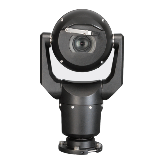
- Page 1 MIC IP starlight 7000i MIC-7502-Z30B│MIC-7502-Z30W│MIC-7502-Z30G Installation Manual...
-
Page 3: Table Of Contents
Typical IP Configuration with High PoE midspan (no I/O connections) Typical Configuration with MIC-ALM-WAS-24 Typical IP Configuration with VJC-7000-90 Illumination/Wiper Maintenance Decommissioning 12.1 Transfer 12.2 Disposal Appendices 13.1 Best Practices for Outdoor Installation 13.2 Error Codes 13.3 AUX Commands Bosch Security Systems Installation Manual 2017.09 | 0.12 | F.01U.xxx.xxx... -
Page 4: Safety
Legal Information Copyright This manual is the intellectual property of Bosch Security Systems, Inc. and is protected by copyright. All rights reserved. Trademarks All hardware and software product names used in this document are likely to be registered trademarks and must be treated accordingly. -
Page 5: Important Safety Instructions
– Do not point the camera at the sun. Bosch Security Systems will not be liable for any damage to cameras that have been pointed directly at the sun. –... -
Page 6: Important Notices
Notice! Bosch recommends the use of surge/lightning protection devices (sourced locally) to protect network and power cables and the camera installation site. Refer to NFPA 780, Class 1 & 2, UL96A, or the equivalent code appropriate for your country/region, and to local building codes. - Page 7 Camera signal - Protect the cable with a primary protector if the camera signal is beyond 140 feet, in accordance with NEC800 (CEC Section 60). Environmental statement - Bosch has a strong commitment towards the environment. This unit has been designed to respect the environment as much as possible.
- Page 8 This equipment generates, uses, and radiates radio frequency energy and, if not installed and used in accordance with the 2017.09 | 0.12 | F.01U.xxx.xxx Installation Manual Bosch Security Systems...
- Page 9 Interference Problems (Comment identifier et résoudre les problèmes d’interférences de radio et de télévision). Cette brochure est disponible auprès du U.S. Government Printing Office, Washington, DC 20402, États-Unis, sous la référence n° 004-000-00345-4. Bosch Security Systems Installation Manual 2017.09 | 0.12 | F.01U.xxx.xxx...
-
Page 10: Customer Support And Service
| Safety MIC IP starlight 7000i Customer Support and Service If this unit needs service, contact the nearest Bosch Security Systems Service Center for authorization to return and shipping instructions. Service Centers Telephone: 800-366-2283 or 585-340-4162 Fax: 800-366-1329 Email: cctv.repair@us.bosch.com... -
Page 11: Unpacking
Verify that all the parts listed in the Parts List below are included. If any items are missing, notify your Bosch Security Systems Sales or Customer Service Representative. – Do not use this product if any component appears to be damaged. Please contact Bosch Security Systems in the event of damaged goods. –... -
Page 12: Product Description
Sunshield (white only) MIC-ILx-300 User-installable illuminator MVS-FCOM-PRCL Serial protocol license for IP cameras accessory specifically for MIC IP starlight 7000i cameras, in - MIC-ILB-300 Black - MIC-ILW-300 White - MIC-ILG-300 Grey 2017.09 | 0.12 | F.01U.xxx.xxx Installation Manual Bosch Security Systems... -
Page 13: Installation Overview
® Electrical Code (NEC)), Canadian Electrical Code, Part I (also called CE Code or CSA C22.1), and all applicable local codes. Bosch Security Systems, Inc. accepts no liability for any damages or losses caused by incorrect or improper installation. Caution! -
Page 14: Configuration Programming In The Shipping Box
“Inverted,” remove the camera from the box and configure it by following the steps in Configuration Programming on a Temporary Table-top Stand, page 15. 4. Disconnect the wires/cables from the connectors in the base of the camera. 2017.09 | 0.12 | F.01U.xxx.xxx Installation Manual Bosch Security Systems... -
Page 15: Configuration Programming On A Temporary Table-Top Stand
(180°). Note that the visor will now be near the body of the camera. 6. Disconnect the wires/cables from the connectors in the base of the camera. Bosch Security Systems Installation Manual 2017.09 | 0.12 | F.01U.xxx.xxx... -
Page 16: Mounting
If the camera is installed in a highly exposed location where lightning strikes may occur, then Bosch recommends installing a separate lightning conductor within 0.5 m (1.6 ft) of the camera and at least 1.5 m (4.9 ft) higher than the camera. A good earth bonding connection to the camera housing itself will provide protection against damage from secondary strikes. - Page 17 (370 mm (14.6 in.)) for the camera head to pan. Figure 7.1: Top view of canted MIC7000 illustrating distance of pan clearance The figure below illustrates the tilt range of the camera in upright orientation. Bosch Security Systems Installation Manual 2017.09 | 0.12 | F.01U.xxx.xxx...
- Page 18 | Mounting MIC IP starlight 7000i 90° 90° 55° 55° Figure 7.2: MIC7000 Tilt Range: 145° each direction; 290° if AutoPivot enabled 2017.09 | 0.12 | F.01U.xxx.xxx Installation Manual Bosch Security Systems...
-
Page 19: Mounting Bracket Options And Accessories
MIC IP starlight 7000i Mounting | en Mounting Bracket Options and Accessories Bosch sells a complete series of mounting brackets that support multiple mounting configurations. You can install the camera: – onto a MIC-DCA or a MIC wall mount –... - Page 20 Note: The figure identifies the part numbers, as well as the codes for the available colors (-BD for black, -WD for white, and -MG for grey) of each mounting accessory. Figure 7.3: Typical Pole mount configuration Figure 7.4: Typical Wall mount configuration 2017.09 | 0.12 | F.01U.xxx.xxx Installation Manual Bosch Security Systems...
- Page 21 Figure 7.5: Typical Corner mount configuration Surface Mount Figure 7.6: Direct surface mount – camera upright (MIC + base gasket) Figure 7.7: Direct surface mount – camera inverted (MIC + base gasket + IP67 Weatherization/Connector Kit) Bosch Security Systems Installation Manual 2017.09 | 0.12 | F.01U.xxx.xxx...
-
Page 22: Canting The Camera
Do not, under any circumstances, cant the camera while the camera is on its side. Cant the camera from an upright position only, in order to prevent screws or other objects from falling into the open spaces in the arms when the yoke caps are removed. 2017.09 | 0.12 | F.01U.xxx.xxx Installation Manual Bosch Security Systems... - Page 23 DCA, with the DCA base upright! It is unstable and might fall and cause bodily injury and/or damage to the camera. Bosch strongly recommends canting the camera after attaching it to a DCA and mounting it in the desired location.
- Page 24 Do not cant the camera, or let it fall, in the wrong direction! The camera should cant only in the direction indicated in the figure directly below. Figure 7.11: Cant the camera head 2017.09 | 0.12 | F.01U.xxx.xxx Installation Manual Bosch Security Systems...
- Page 25 (≈ 12.5 ft lb) ≈ 17 N m (≈ 12.5 ft lb) ≈ 17 N m (≈ 12.5 ft lb) 9. Attach the yoke caps using the supplied spanner wrench. Bosch Security Systems Installation Manual 2017.09 | 0.12 | F.01U.xxx.xxx...
- Page 26 | Mounting MIC IP starlight 7000i 0.0mm - 0.5mm Figure 7.13: Attach yoke caps 10. Canting is complete. 2017.09 | 0.12 | F.01U.xxx.xxx Installation Manual Bosch Security Systems...
-
Page 27: Connections
The camera can be powered by a network compliant to High Power-over-Ethernet using a Bosch model of High PoE Midspan (sold separately) or other device known to be compatible. With this configuration, only a single (Cat5e/Cat6e) cable connection is required to view, to power, and to control the camera. -
Page 28: Ethernet Connections
For models with attached illuminators: Use the 95 W midspan sold by Bosch. For models without illuminators: Use the 60 W midspan sold by Bosch, or a midspan that is compliant to the IEEE 802.3at, class 4 standard. Note: Consult the National Electrical Code (NEC) or other regional standards for cable bundling requirements and limitations. -
Page 29: Connect The Camera To The Network
Note: If the MIC camera will be installed directly to a mounting surface, instead of onto a MIC DCA or a MIC wall mount bracket, Bosch recommends using the connector kit for your model of camera to protect the connections against moisture and dust particles. Each kit provides components for connecting as many as 5 MIC cameras. -
Page 30: Typical System Configurations
5 Data-only IP cable (Cat5e/Cat6e) (user-supplied) between midspan and head-end network Note: The total length of Cat5e/Cat6e cable must be less than 100 m (328 ft) between the camera and the head-end system. 2017.09 | 0.12 | F.01U.xxx.xxx Installation Manual Bosch Security Systems... -
Page 31: Typical Configuration With Mic-Alm-Was-24
4 MIC-ALM-WAS-24 enclosure 9 Alarm input / output interface cables (user-supplied) 5 Interface cable for 24 VAC (user- 10 Monitored Normally Open switch for supplied) for MIC-ALM-WAS-24 Supervised Alarm (user-supplied) Bosch Security Systems Installation Manual 2017.09 | 0.12 | F.01U.xxx.xxx... -
Page 32: Typical Ip Configuration With Vjc-7000-90
Cat5e/Cat6e = 100 m max. Figure 9.3: Basic configuration with VIDEOJET connect 7000 1 Ethernet (network) cable (Cat5e/Cat6e) (user-supplied) between a Bosch camera and the port labeled PoE on VIDEOJET connect 7000 2 Data-only IP cable (Cat5e/Cat6e) to the head-end network Note: The cable to the head-end also can be fiber optic cable from one of the two SFP slots. -
Page 33: Illumination/Wiper
Select the number of minutes (from 1 to 30) after which the White light will turn off after activation. Illuminator compensation Select Auto to configure the camera to compensate automatically for the illuminator. Select Off to turn off illuminator compensation. Wiper Bosch Security Systems Installation Manual 2017.09 | 0.12 | F.01U.xxx.xxx... - Page 34 Intermittent: Wipes twice, then stops. Every 15 seconds, this cycle repeats until users select another option in this field. – One shot: Wipes five times, then turns off. Wiper/washer Click Start to start the wiper/washer. Click Stop to stop the wiper/washer. 2017.09 | 0.12 | F.01U.xxx.xxx Installation Manual Bosch Security Systems...
-
Page 35: Maintenance
No User-serviceable Parts Except for the external wiper blade, the device contains no user-serviceable parts. Contact your local Bosch service center for device maintenance and repair. In the event of failure, the device should be removed from site for repair. -
Page 36: Decommissioning
12.2 Disposal Disposal Your Bosch product has been developed and manufactured using high- quality materials and components that can be reused. This symbol means that electronic and electrical devices that have reached the end of their working life must be disposed of separately from household waste. -
Page 37: Appendices
(AUTODOME and MIC) outdoors with surge and lightning protection. Note that the illustration does not include representations of all models of AUTODOME and MIC cameras. Figure 13.1: Correct outdoor installation with proper surge/lightning protection Bosch Security Systems Installation Manual 2017.09 | 0.12 | F.01U.xxx.xxx... - Page 38 13 Down Conductor; refer to NFPA 780, 14 Install outdoor High PoE-compatible Class 1 and 2. surge protection as close as possible to the camera. Connect to the Equipment Grounding Electrode. 15 Lightning Rod Grounding Electrode 2017.09 | 0.12 | F.01U.xxx.xxx Installation Manual Bosch Security Systems...
-
Page 39: Error Codes
21 VAC and 30 VAC. Bosch Security Systems Installation Manual 2017.09 | 0.12 | F.01U.xxx.xxx... - Page 40 2. Verify the integrity/tightness of the external fasteners. Tighten where necessary. 3. If obvious damage is present, stop using the camera and contact the nearest Bosch Security Systems Service Center. 4. If no damage is evident, power the camera off and then on, and then evaluate operational performance.
- Page 41 4. If damage to the seals is obvious, contact the nearest Bosch Security Systems Service Center. 5. If no obvious damage is found, power the camera off and then on. If the status code reappears, contact the nearest Bosch Security Systems Service Center.
- Page 42 (and the window defrosters, for MIC IP fusion 9000i). If the log notes heater or defroster failure, contact the nearest Bosch Security Systems Service Center. 3. If operation is obstructed because of...
- Page 43 (Configuration > Camera > Installer Menu >Reboot device). If this action does not resolve the problem, contact the nearest Bosch Security Systems Service Center. The Service Center may request information from the diagnostics log of the camera (accessible from the Service menu).
-
Page 44: Aux Commands
Digital Zoom lock On/Off Sector Blanking On/Off Privacy Masking On/Off Proportional Speed On/- Recalibrate Azimuth Compass On/Off Azimuth/Elevation Display On/Off Compass Points Display On/Off Record Tour A On/Off Record Tour B 2017.09 | 0.12 | F.01U.xxx.xxx Installation Manual Bosch Security Systems... - Page 45 Command Description On/Off IR mode AUX ON sets IR to Auto. AUX OFF sets IR to OFF. Available for only. On/Off Night mode IR Filter In/Out On/Off White light illumination Bosch Security Systems Installation Manual 2017.09 | 0.12 | F.01U.xxx.xxx...
- Page 47 Bosch Security Systems B.V. Torenallee 49 5617 BA Eindhoven Netherlands www.boschsecurity.com © Bosch Security Systems B.V., 2017...