
Related Manuals for Bosch MIC-7522


Summary of Contents for Bosch MIC-7522
- Page 1 MIC IP ultra 7100i │ MIC IP starlight 7100i MIC‑7504│MIC‑7522 Installation Manual...
-
Page 3: Table Of Contents
Typical IP Configuration with High PoE midspan (no I/O connections) 15.2 Typical Configuration with MIC-ALM-WAS-24 Troubleshooting 16.1 Physical reset button Maintenance Disposal Technical data Best Practices for Outdoor Installation Error Codes AUX Commands Bosch Security Systems Installation Manual 2019-12 | 1.2 |... -
Page 4: Safety
Legal Information Copyright This manual is the intellectual property of Bosch Security Systems, and is protected by copyright. All rights reserved. Trademarks All hardware and software product names used in this document are likely to be registered trademarks and must be treated accordingly. -
Page 5: Safety Precautions
Notice! This symbol indicates information or a company policy that relates directly or indirectly to the safety of personnel or protection of property. Bosch Security Systems Installation Manual 2019-12 | 1.2 |... -
Page 6: Important Safety Instructions
– Do not point the camera at the sun. Bosch Security Systems will not be liable for any damage to cameras that have been pointed directly at the sun. 2019-12 | 1.2 |... - Page 7 Notice! Bosch recommends the use of surge/lightning protection devices (sourced locally) to protect network and power cables and the camera installation site. Refer to NFPA 780, Class 1 & 2, UL96A, or the equivalent code appropriate for your country/region, and to local building codes.
-
Page 8: Important Notices
Camera signal - Protect the cable with a primary protector if the camera signal is beyond 140 feet, in accordance with NEC800 (CEC Section 60). 2019-12 | 1.2 | Installation Manual Bosch Security Systems... - Page 9 MIC IP ultra 7100i │ MIC IP starlight 7100i Safety | en Environmental statement - Bosch has a strong commitment towards the environment. This device has been designed to respect the environment as much as possible. Electrostatic-sensitive device - Use proper ESD safety precautions when handling the camera to avoid electrostatic discharge.
- Page 10 MIC IP ultra 7100i High-definition 4K PTZ camera MIC IP starlight 7100i High-definition PTZ camera Note: Changes or modifications not expressly approved by Bosch could void the user’s authority to operate the equipment. FCC & ICES Information (U.S.A. and Canadian Models Only) This device complies with part 15 of the FCC Rules.
-
Page 11: Important Notices - Illumination Safety
200 mm 2.19 100 s 200 mm 0.386 Infrared Hazard Hazard 279 mm Distance Retinal Blue Light 10,000 s 200 mm 22.9 100s 200 mm 0.266 Hazard Hazard 2675 mm Distance Bosch Security Systems Installation Manual 2019-12 | 1.2 |... -
Page 12: Customer Support And Service
| Safety MIC IP ultra 7100i │ MIC IP starlight 7100i Customer Support and Service If this unit needs service, contact the nearest Bosch Security Systems Service Center for authorization to return and shipping instructions. Telephone: 800-366-2283 Fax: 800-366-1329 Email: cctv.repair@us.bosch.com... -
Page 13: Introduction
You can also use the Project Assistant app to complete the initial configuration of the camera. In order to use this device with the Project Assistant app by Bosch, you must download the app from the Bosch Download Store, from Google Play, or from the Apple Store. -
Page 14: Additional Tools
MIC IP ultra 7100i │ MIC IP starlight 7100i Additional Tools The following table lists additional tools (not supplied by Bosch) that may be required to install a MIC camera or its accessories: 1 Phillips-head screwdriver to secure the ground lug of the camera... -
Page 15: Product Description
Make sure that the installation conditions comply with the specified stresses of vibration and shock as mentioned in the datasheet. A long-life silicone wiper blade mounted on a spring-loaded arm is standard on all MIC cameras. Bosch Security Systems Installation Manual 2019-12 | 1.2 |... -
Page 16: Overview Of Installation Steps
Electrical Code ® (NEC)), Canadian Electrical Code, Part I (also called CE Code or CSA C22.1), and all applicable local codes. Bosch Security Systems accepts no liability for any damages or losses caused by incorrect or improper installation. Caution! ELECTRIC SHOCK HAZARD... -
Page 17: Mounting
Mounting Mounting Location and Orientation Options Bosch designed MIC IP 7100i cameras for use in outdoor applications. In an enclosed installation area (for example, in a foundry, near a furnace, etc.), temperatures outside of the camera might exceed +65 °C (+149 °F). If you install a camera in an enclosed area, make sure that the operating temperature of the camera is a maximum of +60 °C (+140 °F). -
Page 18: Mounting Options
If the camera is installed in a highly exposed location where lightning strikes may occur, then Bosch recommends installing a separate lightning conductor within 0.5 m (1.6 ft) of the camera and at least 1.5 m (4.9 ft) higher than the camera. A good earth bonding connection to the camera housing itself will provide protection against damage from secondary strikes. - Page 19 See the figures below for illustrations of the correct and the incorrect mounting orientations of MIC cameras. Correct mounting orientation - upright Correct mounting orientation - inverted 90° 90° 55° 55° Figure 5.1: Tilt range, MIC IP ultra 7100i Bosch Security Systems Installation Manual 2019-12 | 1.2 |...
-
Page 20: Mounting Bracket Options
Bosch sells a complete series of mounting brackets that support multiple mounting configurations. Always use only Bosch-supplied mounts, which are designed for safe installation of your MIC camera. Refer to the MIC Series Mounting Brackets Installation Guide for complete installation instructions. -
Page 21: Considerations For Mounting The Camera In Inverted Orientation
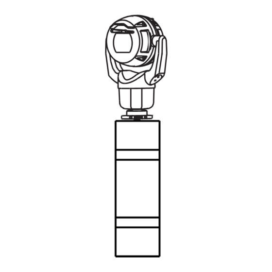
The camera head will rotate automatically into inverted position (180°). Note the position of the visor when the camera is installed in inverted orientation. The visor will now be near the body of the camera. Bosch Security Systems Installation Manual 2019-12 | 1.2 |... - Page 22 Seal the mount so that moisture or water cannot collect and stay in the bottom of the MIC camera. The figure that follows shows the camera installed in inverted orientation on a pole. Figure 5.6: MIC camera mounted in inverted orientation (on pole) 2019-12 | 1.2 | Installation Manual Bosch Security Systems...
-
Page 23: Optional) Installing An Sd Card
(Optional) Installing an SD card | en (Optional) Installing an SD card The steps that follow are applicable for MIC enhanced models (MIC-7504-Z12xR, MIC-7522- Z30xR). Use a T20 Torx driver to remove the two (2) fasteners from the SD card cover on the rear of the camera head. -
Page 24: (Optional) Configuration Programming In The Shipping Box
3. Configure the camera. Refer to the separate User Manual for details. 4. Disconnect the wires/cables from the connectors in the base of the camera. Refer to – (Optional) Configuration Programming on a Temporary Table-top Stand, page 25 2019-12 | 1.2 | Installation Manual Bosch Security Systems... -
Page 25: Optional) Configuration Programming On A Temporary Table-Top Stand
(180°). Note that the visor will now be near the body of the camera. 6. Disconnect the wires/cables from the connectors in the base of the camera. Bosch Security Systems Installation Manual 2019-12 | 1.2 |... -
Page 26: Installing A Mic Camera On A Hinged Dca
Phillips-head screwdriver to attach ground wire * (Optional) MOLYKOTE® 111 grease [from Dow Corning] for primary O-ring Warning! Ensure not to damage the paint on the housing of the camera or the mount. 2019-12 | 1.2 | Installation Manual Bosch Security Systems... - Page 27 Installing a MIC Camera on a Hinged DCA | en 3/4” NPT 1. Attach the DCA to the mounting location using user-supplied hardware (item 1). (Bosch recommends stainless steel bolts and washers.) 2. Attach user-supplied conduit or glands to the side hole or to the bottom hole. If applicable, use the conduit adapter (male M25 to female ¾...
- Page 28 5. Insert the O-ring (item 1). 6. Loosen the Torx bolts two (2) turns (items 2). Slide the hook up (item 3). Tighten the bolts to hold the hook in place temporarily (item 4). 2019-12 | 1.2 | Installation Manual Bosch Security Systems...
- Page 29 Fully tighten the hook bolts (item 3). 9. Carefully tilt the camera to the side with the pin under the hook. Bosch Security Systems Installation Manual 2019-12 | 1.2 |...
- Page 30 10. Make the appropriate electrical connections. Refer to the chapter Connections for more information. 11. Connect the lead from the camera pigtail to the ground post on the pan base. The connection for the customer should be to the lead from the post. 2019-12 | 1.2 | Installation Manual Bosch Security Systems...
- Page 31 17 N m (12.5 ft lb) 12. Carefully tip the camera to its final position. Avoid pinching wires between the camera base and the DCA! Insert four washers and hex bolts (supplied). Bosch Security Systems Installation Manual 2019-12 | 1.2 |...
-
Page 32: Optional) Installing A Sunshield
Discard the cut-out plastic. Note: This step does not apply to cameras mounted in inverted orientation. Remove the screws from the camera head. #2 Philips Attach the sunshield to the camera head. 2019-12 | 1.2 | Installation Manual Bosch Security Systems... - Page 33 (Optional) Installing a Sunshield | en Make sure that the tabs in the sunshield lock into place in the camera head. Install the M4 x 10 screws. Tighten the screws to 2.2 N m (19.5 in-lb). Bosch Security Systems Installation Manual 2019-12 | 1.2 |...
- Page 34 MIC IP ultra 7100i │ MIC IP starlight 7100i M4 x 8 2.2 N m (19.5 in lb) Note that when you install the sunshield correctly, the sunshield appears as in the following figure. Figure 10.1: Sunshield installation is complete. 2019-12 | 1.2 | Installation Manual Bosch Security Systems...
-
Page 35: Optional) Installing The Illuminator
Installer Menu > Orientation, and then select “Inverted”. Click Set to confirm the selection. The camera head will rotate automatically into inverted position (180°). Regardless of mounting orientation, the visor should always be above the camera window. Bosch Security Systems Installation Manual 2019-12 | 1.2 |... - Page 36 For upright cameras, remove the plug near the visor. For inverted cameras, remove the plug farther away from the visor. Bosch suggests storing the access plug inside the DCA mount (or wall mount accessory) in case it becomes necessary to remove the illuminator.
- Page 37 MIC IP ultra 7100i │ MIC IP starlight 7100i (Optional) Installing the Illuminator | en 287.93 mm (11.34 in.) 8. Installation of the illuminator is complete. Bosch Security Systems Installation Manual 2019-12 | 1.2 |...
-
Page 38: (Optional) Canting The Camera
Do not put a canted (35°) camera in an upright position on the camera base or on an unsecured DCA. In this position, the camera can fall over and can cause injury or be damaged. Put the canted camera on its side until installation. 2019-12 | 1.2 | Installation Manual Bosch Security Systems... - Page 39 Bosch strongly recommends attaching the camera to a DCA and mounting the DCA before canting the camera. To cant the camera, follow these steps: 1.
- Page 40 (12.5 ft lb) 17 Nm (12.5 ft lb) 9. Attach the yoke caps using the supplied spanner wrench. Note: Tighten each yoke cap until it is flush with the yoke arm. 2019-12 | 1.2 | Installation Manual Bosch Security Systems...
- Page 41 Figure 12.6: Canting is complete. 11. Change the camera orientation to “Canted.” Complete the following steps: – Access the page Configuration. – Navigate to Camera > Installer Menu > Orientation. – Select “Canted.” Bosch Security Systems Installation Manual 2019-12 | 1.2 |...
-
Page 42: Replacing A Wiper Assembly
MIC IP ultra 7100i │ MIC IP starlight 7100i Replacing a wiper assembly Put a piece of thin, protective material between the window glass and the wiper to prevent accidental damage. 2019-12 | 1.2 | Installation Manual Bosch Security Systems... - Page 43 With one hand, hold the wiper arm firmly in place to restrict rotational movement. With the other hand, using a 7mm Hex socket or nut driver, rotate the acorn nut counter- clockwise until the nut is free from the wiper shaft. Bosch Security Systems Installation Manual 2019-12 | 1.2 |...
- Page 44 MIC IP ultra 7100i │ MIC IP starlight 7100i Remove the wiper spring, hub, arm, and blade assembly from the wiper shaft. Assemble the new wiper arm on the new wiper hub. 2019-12 | 1.2 | Installation Manual Bosch Security Systems...
- Page 45 MIC IP ultra 7100i │ MIC IP starlight 7100i Replacing a wiper assembly | en Insert the new blade assembly into the new wiper arm. Slide the new wiper hub and the attached parts onto the wiper shaft. Bosch Security Systems Installation Manual 2019-12 | 1.2 |...
- Page 46 | Replacing a wiper assembly MIC IP ultra 7100i │ MIC IP starlight 7100i Slide the new wiper spring onto the wiper shaft and over the new wiper arm. 2019-12 | 1.2 | Installation Manual Bosch Security Systems...
- Page 47 Replacing a wiper assembly | en Apply Loctite 243 to the cavity of the acorn nut. 10. Lightly thread the new acorn nut onto the wiper shaft over the new wiper spring and new wiper hub. Bosch Security Systems Installation Manual 2019-12 | 1.2 |...
- Page 48 12. With the other hand, using a 7mm Hex socket or nut driver, tighten the new acorn nut clockwise to a torque value of 1.0 Nm. 2019-12 | 1.2 | Installation Manual Bosch Security Systems...
-
Page 49: Connections
24 VAC. After the High PoE Midspan power source is restored, the camera switches power input again to the High PoE Midspan. Bosch recommends 24VAC power output of 24V at 100VA, 4A with a slow blow fuse. The power supply must be certified to UL/IEC 60950-1 2nd Edition, AM1+AM2 or UL/IEC 62368-1 2nd Ed, Output 24 VAC, LPS, +65 °C (+149 °F) min. -
Page 50: Ethernet Connections
Note: If the MIC camera will be installed directly to a mounting surface, instead of onto a MIC DCA or a MIC wall mount bracket, Bosch recommends using the connector kit for your model of camera to protect the connections against moisture and dust particles. Each kit provides components for connecting as many as 5 MIC cameras. -
Page 51: Typical System Configurations
Midspan and the head-end network Note: The total length of Cat5e/Cat6 Shielded Twisted Pair (STP) cable must be less than 100 m (328 ft) between the camera and the head-end system. Bosch Security Systems Installation Manual 2019-12 | 1.2 |... -
Page 52: Typical Configuration With Mic-Alm-Was-24
7 Washer pump accessory (user- 8 Interface cable for washer control supplied) (user-supplied) 9 Interface cables for alarm inputs and 10 Switch (monitored, normally open) for outputs (user-supplied) supervised alarm (user-supplied) 2019-12 | 1.2 | Installation Manual Bosch Security Systems... -
Page 53: Troubleshooting
Camera reboots frequently or Your camera has an improper network connection. intermittently Test your camera with another power supply. Check the Bosch website for a software update that might address the issue. 16.1 Physical reset button Each camera has a hardware reset button. You may need to press the reset button to reset the camera to factory defaults if you encounter the following circumstances: –... - Page 54 | Troubleshooting MIC IP ultra 7100i │ MIC IP starlight 7100i 2019-12 | 1.2 | Installation Manual Bosch Security Systems...
-
Page 55: Maintenance
No User-serviceable Parts Except for the external wiper blade, the device contains no user-serviceable parts. Contact your local Bosch service center for device maintenance and repair. In the event of failure, the device should be removed from site for repair. -
Page 56: Disposal
MIC IP ultra 7100i │ MIC IP starlight 7100i Disposal Disposal Your Bosch product has been developed and manufactured using high- quality materials and components that can be reused. This symbol means that electronic and electrical devices that have reached the end of their working life must be disposed of separately from household waste. -
Page 57: Technical Data
MIC IP ultra 7100i │ MIC IP starlight 7100i Technical data | en Technical data For product specifications, see the datasheet for your camera, available on the appropriate product pages of the Online Product Catalog at www.boschsecurity.com. Bosch Security Systems Installation Manual 2019-12 | 1.2 |... -
Page 58: Best Practices For Outdoor Installation
AUTODOME and MIC cameras. The illustration can represent any IP camera. Mounting hardware varies between units. Figure 20.1: Correct outdoor installation with proper surge/lightning protection 2019-12 | 1.2 | Installation Manual Bosch Security Systems... - Page 59 13 Down Conductor; refer to NFPA 780, 14 Install outdoor High PoE-compatible Class 1 and 2. surge protection as close as possible to the camera. Connect to the Equipment Grounding Electrode. 15 Lightning Rod Grounding Electrode Bosch Security Systems Installation Manual 2019-12 | 1.2 |...
-
Page 60: Error Codes
21 VAC and 30 VAC. Camera may be operating in an 1. Verify that the ambient temperature is not environment where ambient below -40 °C (-40 °F). temperature is below the specification of the camera. 2019-12 | 1.2 | Installation Manual Bosch Security Systems... - Page 61 2. Verify the integrity/tightness of the external fasteners. Tighten where necessary. 3. If obvious damage is present, stop using the camera and contact the nearest Bosch Security Systems Service Center. 4. If no damage is evident, power the camera off and then on, and then evaluate operational performance.
- Page 62 Configure the washer pre-position. If without washer pre-position being necessary, refer to the subchapter “Using the stored. Wiper/Washer (Bosch AUX/Pre-position Commands)” in the User Manual for details on configuring washer functions. Attempt was made to move to a pre- 1. Select/configure a different pre-position position that is mapped to an number for the desired location.
- Page 63 (and the window defrosters, for MIC IP fusion 9000i). If the log notes heater or defroster failure, contact the nearest Bosch Security Systems Service Center. 3. If operation is obstructed because of...
- Page 64 | Error Codes MIC IP ultra 7100i │ MIC IP starlight 7100i If this action does not resolve the problem, contact the nearest Bosch Security Systems Service Center. The Service Center may request information from the diagnostics log of the camera (accessible from the Service menu).
-
Page 65: Aux Commands
Sector Blanking On/Off Privacy Masking On/Off Proportional Speed On/- Recalibrate Azimuth Compass On/Off Azimuth/Elevation Display On/Off Compass Points Display On/Off Record Tour A On/Off Record Tour B On/Off Wiper On/Off (Continuous) Bosch Security Systems Installation Manual 2019-12 | 1.2 |... - Page 66 Function Command Description On/Off IR mode AUX ON sets IR to Auto. AUX OFF sets IR to OFF. Available for only. On/Off Night mode IR Filter In/Out On/Off White light illumination 2019-12 | 1.2 | Installation Manual Bosch Security Systems...
- Page 67 MIC IP ultra 7100i │ MIC IP starlight 7100i AUX Commands | Bosch Security Systems Installation Manual 2019-12 | 1.2 |...
- Page 68 | AUX Commands MIC IP ultra 7100i │ MIC IP starlight 7100i 2019-12 | 1.2 | Installation Manual Bosch Security Systems...
- Page 70 Bosch Security Systems B.V. Torenallee 49 5617 BA Eindhoven Netherlands www.boschsecurity.com © Bosch Security Systems B.V., 2020...