Bosch MIC IP fusion 9000i Installation Manual
Hide thumbs
Also See for MIC IP fusion 9000i:
- Operation manual (80 pages) ,
- Installation manual (60 pages) ,
- User manual (93 pages)
Table of Contents
Advertisement
Quick Links
Advertisement
Table of Contents

Related Manuals for Bosch MIC IP fusion 9000i


Summary of Contents for Bosch MIC IP fusion 9000i
- Page 1 MIC IP fusion 9000i MIC‑9502‑Z30xxx Installation Manual...
-
Page 3: Table Of Contents
MIC IP fusion 9000i Table of contents | en Table of contents Safety About this Manual Legal Information Safety Precautions Important Safety Instructions Important Notices Customer Support and Service Unpacking Parts List - Camera Additional Tools Product Description Installation Overview... -
Page 4: Safety
Legal Information Copyright This manual is the intellectual property of Bosch Security Systems, Inc. and is protected by copyright. All rights reserved. Trademarks All hardware and software product names used in this document are likely to be registered trademarks and must be treated accordingly. -
Page 5: Important Safety Instructions
– Do not point the camera at the sun. Bosch Security Systems will not be liable for any damage to cameras that have been pointed directly at the sun. When transporting, take extra care to protect the wiper and the camera window(s). -
Page 6: Important Notices
Notice! Bosch recommends the use of surge/lightning protection devices (sourced locally) to protect network and power cables and the camera installation site. Refer to NFPA 780, Class 1 & 2, UL96A, or the equivalent code appropriate for your country/region, and to local building codes. - Page 7 Camera signal - Protect the cable with a primary protector if the camera signal is beyond 140 feet, in accordance with NEC800 (CEC Section 60). Environmental statement - Bosch has a strong commitment towards the environment. This unit has been designed to respect the environment as much as possible.
- Page 8 | Safety MIC IP fusion 9000i Heat sources - Do not install unit near any heat sources such as radiators, heaters, or other equipment (including amplifiers) that produce heat. Moving - Before moving the unit, disconnect both the 24 VAC connection and the Ethernet cable connection (if using PoE).
- Page 9 MIC IP fusion 9000i Safety | en instruction manual, may cause harmful interference to radio communications. Operation of this equipment in a residential area is likely to cause harmful interference, in which case the user will be required to correct the interference at his expense.
-
Page 10: Customer Support And Service
| Safety MIC IP fusion 9000i Customer Support and Service If this unit needs service, contact the nearest Bosch Security Systems Service Center for authorization to return and shipping instructions. Telephone: 800-366-2283 Fax: 800-366-1329 Email: cctv.repair@us.bosch.com Customer Service Telephone: 888-289-0096 Fax: 585-223-9180 Email: security.sales@us.bosch.com... -
Page 11: Unpacking
Verify that all the parts listed in the Parts List below are included. If any items are missing, notify your Bosch Security Systems Sales or Customer Service Representative. – Do not use this product if any component appears to be damaged. Please contact Bosch Security Systems in the event of damaged goods. –... -
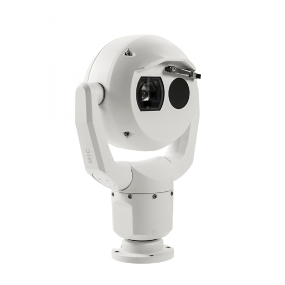
Page 12: Product Description
| Product Description MIC IP fusion 9000i Product Description The MIC IP fusion 9000i camera is a day/night, IP PTZ camera with dual optical/thermal imagers. Ruggedized and weatherproof, the camera offers a reliable, robust, and high-quality surveillance solution for extreme security applications. -
Page 13: Installation Overview
Electrical Code ® (NEC)), Canadian Electrical Code, Part I (also called CE Code or CSA C22.1), and all applicable local codes. Bosch Security Systems, Inc. accepts no liability for any damages or losses caused by incorrect or improper installation. Caution! - Page 14 | Installation Overview MIC IP fusion 9000i Depending on your installation requirements, you may need to complete the following steps: Pre-configuration (Optional) Refer to Configuration Programming in the Shipping Box, page 15. Mounting options Refer to Mounting Bracket Options and Accessories, page 19.
-
Page 15: Configuration Programming In The Shipping Box
MIC IP fusion 9000i Configuration Programming in the Shipping Box | en Configuration Programming in the Shipping Box The camera packaging allows installers to connect the camera to the network and configure the camera still in the box. 1. Remove the packing material to access the camera’s electrical connectors. -
Page 16: Configuration Programming On A Temporary Table-Top Stand
| Configuration Programming on a Temporary Table-top Stand MIC IP fusion 9000i Configuration Programming on a Temporary Table-top Stand Caution! Take extra care lifting or moving MIC cameras because of their weight. The camera (still in the foam) can stand temporarily on a flat, horizontal surface such as a desk or a table during initial network connection and configuration. -
Page 17: Mounting
If the camera is installed in a highly exposed location where lightning strikes may occur, then Bosch recommends installing a separate lightning conductor within 0.5 m (1.6 ft) of the camera and at least 1.5 m (4.9 ft) higher than the camera. A good earth bonding connection to the camera housing itself will provide protection against damage from secondary strikes. -
Page 18: Mounting Orientation Options
The figures below illustrate the tilt range of the camera in upright orientation and in inverted orientation. 90° 90° 56° 56° 56° 56° 56° 56° Tilt range of MIC IP fusion 9000i camera 2018.09 | 1.1 | F.01U.334.820 Installation Manual Bosch Security Systems... -
Page 19: Mounting Bracket Options And Accessories
MIC IP fusion 9000i Mounting | en Mounting Bracket Options and Accessories Bosch sells a complete series of mounting brackets that support multiple mounting configurations. You can install the camera: – onto a MIC-DCA or a MIC wall mount –... - Page 20 | Mounting MIC IP fusion 9000i Typical pole mount configuration (MIC9000) Through-wall Mount Typical direct wall mount (MIC9000 on WMB mounted directly to a wall (gasket required)) Down-wall Mount Typical wall mount with SCA (MIC9000) 2018.09 | 1.1 | F.01U.334.820...
- Page 21 MIC IP fusion 9000i Mounting | en Corner Mount Typical corner mount configuration (MIC9000) Surface Mount Direct surface mount (upright) with base gasket (MIC9000) Direct surface mount (inverted) with base gasket + IP67 Weatherization/Connector Kit Bosch Security Systems Installation Manual...
- Page 22 | Mounting MIC IP fusion 9000i Sunshield accessory MIC IP fusion 9000i camera with sunshield (MIC-9K- SNSHLD-W) installed 2018.09 | 1.1 | F.01U.334.820 Installation Manual Bosch Security Systems...
-
Page 23: Installing The Mic Sunshield
MIC IP fusion 9000i Installing the MIC Sunshield | en Installing the MIC Sunshield Quantity Component Sunshield shells Spike strips Screws Flat washers Quick Installation Guide Additional Tools Required Phillips-head screwdriver, #2, to remove factory-installed plastic screws from the camera head Torx driver, T20, for M4 Torx head screws 1. - Page 24 | Installing the MIC Sunshield MIC IP fusion 9000i #2 Phillips 3. Remove and discard 4 screws. 4. Align the sunshield shells so that the pins slide into the bolt heads on the faceplate. 5. Ensure that the sunshield mounting holes align with the holes in the rear of the camera head.
- Page 25 MIC IP fusion 9000i Installing the MIC Sunshield | en MIC IP fusion 9000i camera with sunshield (MIC-9K- SNSHLD-W) installed 7. If the rear gap is not parallel, rework to ensure that the pins are seated properly in the bolt heads on the faceplate.
-
Page 26: Connections
The camera can be powered by a network compliant to High Power-over-Ethernet using a Bosch model of High PoE Midspan (sold separately) or other device known to be compatible. With this configuration, only a single (Cat5e/Cat6e) cable connection is required to view, to power, and to control the camera. -
Page 27: Ethernet Connections
Terminal Connector RJ45, Male High PoE (95 W) Use a midspan sold by Bosch, or a midspan that is offered as a compatible alternative. Note: Consult the National Electrical Code (NEC) or other regional standards for cable bundling requirements and limitations. -
Page 28: Connect The Camera To The Network
Note: If the MIC camera will be installed directly to a mounting surface, instead of onto a MIC DCA or a MIC wall mount bracket, Bosch recommends using the connector kit for your model of camera to protect the connections against moisture and dust particles. Each kit provides components for connecting as many as 5 MIC cameras. -
Page 29: Typical System Configurations
MIC IP fusion 9000i Typical System Configurations | en Typical System Configurations MIC IP fusion 9000i System Configuration Options Bosch Security Systems Installation Manual 2018.09 | 1.1 | F.01U.334.820... -
Page 30: Troubleshooting
| Troubleshooting MIC IP fusion 9000i Troubleshooting Table of Troubleshooting Issues The table below identifies issues that could occur with the camera, and how to resolve them. Note: Refer to the Error Codes section of the manual for descriptions of the error codes that appear on the OSD. - Page 31 (optical image). Camera reboots frequently or Test your camera with another power supply. intermittently Check the Bosch website for a software update that might address the issue. No OSD messages appear. Bosch’s Video SDK is required. Video management software from third parties does not use the SDK.
- Page 32 | Troubleshooting MIC IP fusion 9000i Problem Explanation Solution The picture shows Check to see if there the heat images that aren’t of objects are being reflected present in the scene. off a surface causing thermal reflections. 2018.09 | 1.1 | F.01U.334.820...
-
Page 33: Maintenance
No User-serviceable Parts Except for the external wiper blade, the device contains no user-serviceable parts. Contact your local Bosch service center for device maintenance and repair. In the event of failure, the device should be removed from site for repair. -
Page 34: Decommissioning
13.2 Disposal Disposal Your Bosch product has been developed and manufactured using high- quality materials and components that can be reused. This symbol means that electronic and electrical devices that have reached the end of their working life must be disposed of separately from household waste. -
Page 35: Appendices
MIC IP fusion 9000i Appendices | en Appendices 14.1 Best Practices for Outdoor Installation Cameras installed outdoors are susceptible to surges and lightning. Always include surge and lightning protection when installing outdoor cameras. The following figure is an illustration of the proper configuration for installing IP PTZ cameras (AUTODOME and MIC) outdoors with surge and lightning protection. - Page 36 | Appendices MIC IP fusion 9000i 1 Indoor main building 2 Network equipment 3 Connect the ground of the camera 4 Surge protection power supply to the building earth ground. 5 Connect the ground of the camera to 6 Install Cat5e/Cat6e Ethernet (Shielded the ground of the surge protector.
-
Page 37: Aux Commands
MIC IP fusion 9000i Appendices | en 14.2 AUX Commands Function Command Description On/Off Auto Pan without limits (Continuous) On/Off Auto Pan between limits On/Off Run Custom Pre-Position Tour On/Off Run Pre-Position Tour On/Off AutoPivot Enable On/Off Backlight Compensation (BLC) - Page 38 Increase Privacy Mask Size while moving 1-256 Set/- Pre-position Programming 1-256 -/Shot Pre-position Recall The following commands are specific to MIC IP fusion 9000i models. Function Command On/-- Activate color mode White hot --/Off Activate color mode Black hot On/--...
- Page 40 Bosch Security Systems B.V. Torenallee 49 5617 BA Eindhoven Netherlands www.boschsecurity.com © Bosch Security Systems B.V., 2018...