Table of Contents
Advertisement
Sep. 2010
Table of Contents
Cautionary Notes ..............................................................2
Specifications .....................................................................2
Location of Controls .........................................................3
Location of Controls Parts List........................................3
Exploded View (Cabinet).................................................4
Exploded View (Cabinet) Parts List ...............................5
Exploded View (Chassis) .................................................6
Exploded View (Chassis) Parts List................................7
Copyright © 2010 Roland Corporation
All rights reserved. No part of this publication may be reproduced in any form without the written permission
of Roland Corporation.
Parts List .............................................................................8
Verification of Operation ...............................................10
Block Diagram .................................................................12
Board)................................................................................13
Board)................................................................................14
17058697E0
SERVICE NOTES
Issued by RJA
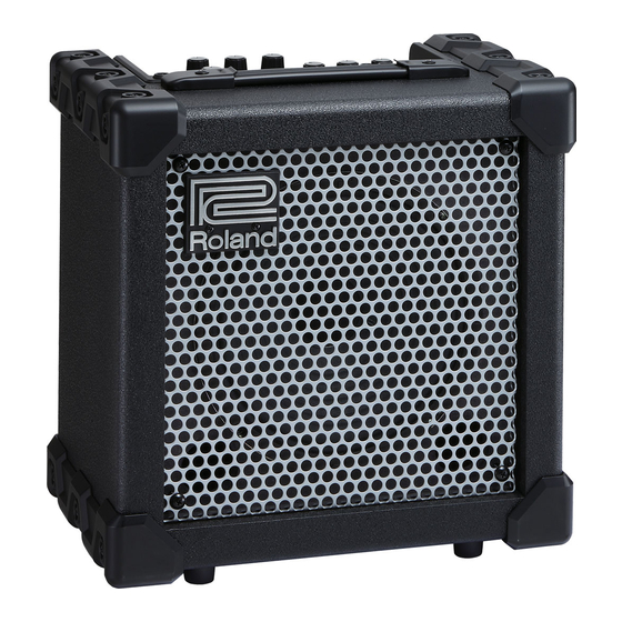
CUBE-15XL
CC-KWS
Advertisement
Table of Contents

Summary of Contents for Roland CUBE-15XL
-
Page 1: Table Of Contents
Circuit Diagram (Main, PRE, PS1, Power Squeezer Exploded View (Chassis) ..........6 Board)................14 Exploded View (Chassis) Parts List........7 Copyright © 2010 Roland Corporation All rights reserved. No part of this publication may be reproduced in any form without the written permission of Roland Corporation. 17058697E0... -
Page 2: Cautionary Notes
• Because the part is made to order (at current market price). Connectors • Because it is carried in electronic data on the Roland web site. INPUT Jack • Because it is a package or an accessory irrelevant to the function AUX IN Jack maintenance of the main body. -
Page 3: Location Of Controls
Sep. 2010 CUBE-15XL Location of Controls fig.panel-15XL.eps Location of Controls Parts List Part Code Part Name Description Q’ty 5100016757 ROTARY POTENTIOMETER RD901F-20E1-15FWA250K-00 * This unit includes the following parts. 17048630 VR ACCESSORY NUT M9 40452178 VR WASHER M9 5100004351 R-KNOB... -
Page 4: Exploded View (Cabinet)
Sep. 2010 CUBE-15XL Exploded View (Cabinet) fig.bunkaizu.eps... -
Page 5: Exploded View (Cabinet) Parts List
Sep. 2010 CUBE-15XL Exploded View (Cabinet) Parts List Part Code Part Name Description Q’ty SD000017 BADGE 5100016519 GRILLE SD000950 SPEAKER (W0804-431A) 20CM/4OHM 5100016544 CABINET ASSY * This unit includes the following parts. ******** CABINET 5100015010 CORNER PROTECTOR 5100015012 TRIM SASH... -
Page 6: Exploded View (Chassis)
Sep. 2010 CUBE-15XL Exploded View (Chassis) fig.chassis.eps... -
Page 7: Exploded View (Chassis) Parts List
Sep. 2010 CUBE-15XL Exploded View (Chassis) Parts List Part Code Part Name Description Q’ty SD000177 AC CORD PSE SP-18A WITH TERMINAL 100V SD000912 AC CORD ASSY SP-20 117V(2P) 5100012741 AC CORD 181-BG429-BL 117VBL 2.5M SD000913 AC CORD ASSY SP-026A 230V(2P) -
Page 8: Parts List
Sep. 2010 CUBE-15XL Parts List fig.-part1-e.eps Due to one or more of the following reasons, Safety Precautions: parts with parts code ******** cannot be supplied as service parts. The parts marked have safety-related characteristics. Use only listed parts for replacement. -
Page 9: Oval Machine Bzc
Sep. 2010 CUBE-15XL AC CORD ASSY (Installed) SD000177 AC CORD PSE SP-18A WITH TERMINAL 100V for 100V SD001068 AC CORD ASSY SP-18B 115V(2P) for 115VTW 5100012741 AC CORD 181-BG429-BL 117VBL 2.5M for 117VBL SD000912 AC CORD ASSY SP-20 117V(2P) for 117VU, 117VU/CS... -
Page 10: Verification Of Operation
Sep. 2010 CUBE-15XL Verification of Operation Set LEAD TYPE to METAL ZONE, and verify that the output value between the red and black speaker wires is +14.5±2.0 dBm. Set LEAD TYPE to EXTREME, and verify that the output value between the red and black speaker wires is +3.0±2.0 dBm. - Page 11 Sep. 2010 CUBE-15XL Measurement of the PHONES Output Values Set the panel buttons and controls as shown below. SELECT: CLEAN CLEAN VOLUME: LEAD TYPE: EXTREME GAIN: VOLUME: EQUALIZER BASS: MIDDLE: TREBLE: POWER SQUEEZER: Input a 1-kHz sine wave at -40 dBm to the INPUT jack.
-
Page 12: Block Diagram
Sep. 2010 CUBE-15XL Block Diagram fig.block-15XL.eps HEAD AMP CLEAN VOLUME CLEAN-CH INPUT LEAD-CH LEAD GAIN LEAD VOLUME EXTREME METAL ZONE DISTORTION OVERDRIVE POWER AMP EQUALIZER BASS MIDDLE TREBLE MUTE SPEAKER 4 PHONES AUX IN POWER SQUEEZER MUTE-CONT POWER SUPPLY AC IN... -
Page 13: Circuit Board (Main, Pre, Ps1, Power Squeezer Board)
Sep. 2010 CUBE-15XL Circuit Board (Main, PRE, PS1, Power Squeezer Board) fig.b-main.eps... -
Page 14: Circuit Diagram (Main, Pre, Ps1, Power Squeezer Board)
Sep. 2010 CUBE-15XL Circuit Diagram (Main, PRE, PS1, Power Squeezer Board) fig.d-main.eps@L... - Page 15 Sep. 2010 CUBE-15XL fig.d-main.eps@R...


