Advertisement
Table of Contents
- 1 Table of Contents
- 2 Specifications
- 3 Location of Controls
- 4 Location of Controls Parts List
- 5 Exploded View(Cabnet)
- 6 Exploded View Parts List(Cabinet)
- 7 Exploded View(Chassis)
- 8 Exploded View Parts List(Chassis)
- 9 Parts List
- 10 Checking the Version Number
- 11 Test Mode
- 12 Cautions for the Replacement of Damaged Power Supply Cord
- Download this manual
Jul.2002
TABLE OF CONTENTS
SPECIFICATIONS.............................................................2
LOCATION OF CONTROLS ..........................................3
LOCATION OF CONTROLS PARTS LIST ...................3
EXPLODED VIEW(CABNET) .........................................4
EXPLODED VIEW PARTS LIST(CABINET) ................5
EXPLODED VIEW(CHASSIS).........................................6
Copyright © 2002 ROLAND CORPORATION
All rights reserved. No part of this publication may be reproduced in any form without the written permission
of ROLAND CORPORATION.
EXPLODED VIEW PARTS LIST(CHASSIS)..................7
PARTS LIST........................................................................8
CHECKING THE VERSION NUMBER.......................10
TEST MODE.....................................................................10
DAMAGED POWER SUPPLY CORD..........................12
17058088E0
SERVICE NOTES
Issued by RJA
Printed in Japan (0800) (NB)
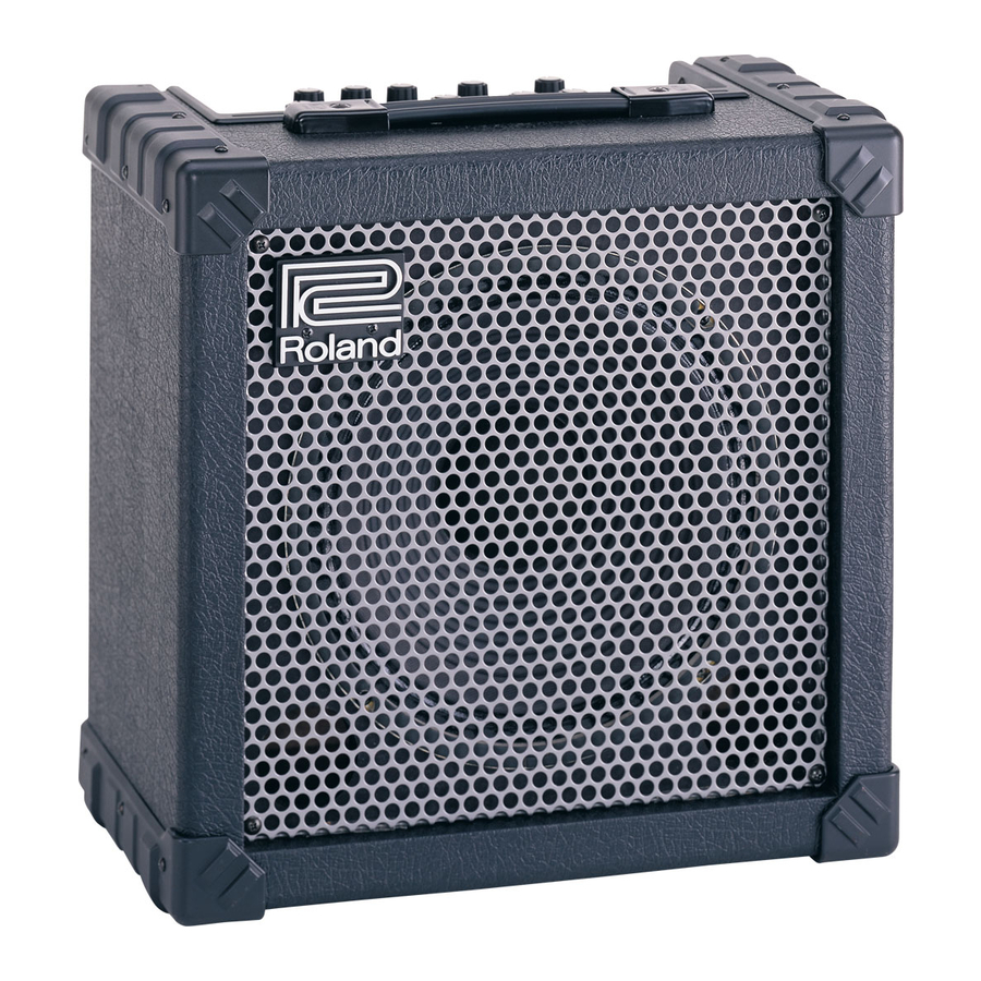
CUBE-30
Advertisement
Table of Contents

Summary of Contents for Roland CUBE 30
-
Page 1: Table Of Contents
EXPLODED VIEW PARTS LIST(CABINET) ....5 CAUTIONS FOR THE REPLACEMENT OF EXPLODED VIEW(CHASSIS).........6 DAMAGED POWER SUPPLY CORD......12 Copyright © 2002 ROLAND CORPORATION All rights reserved. No part of this publication may be reproduced in any form without the written permission of ROLAND CORPORATION. 17058088E0... -
Page 2: Specifications
Jul.2002 SPECIFICATIONS Power Supply AC117V, 230V, 240V CUBE-30 GUITAR AMPLIFIER SPECIFICATIONS Power Consumption Rated Power Output Dimension Nominal Input Level (1kHz) INPUT -10dBu/1Mohms 385 (W) x240 (D) x380 (H) mm AUX IN -10dBu 15”-13/16 (W) x9”-1/2 (D) x15” (H) inches Weights Speaker 25cm (10inch) x1... -
Page 3: Location Of Controls
CUBE-30 LOCATION OF CONTROLS fig.panel30 LOCATION OF CONTROLS PARTS LIST all JACK NUT : SD000042 JACK NUT all KNOB : SD000043 KNOB Part Code Part Name Description Q’ty 13449146 YKB21-5012 (W/SW) 6.5MM JACK SD000044 LED GREEN 2249752100 PUSH BUTTON BLACK #521 SD000059 SPUP128100 PUSH SWITCH... -
Page 4: Exploded View(Cabnet)
Jul.2002 EXPLODED VIEW(CABNET) fig.explo-1 Don’t keep a speaker cable from contact a Heatsink and a primary power supply unit when equipping with a chassis. -
Page 5: Exploded View Parts List(Cabinet)
CUBE-30 EXPLODED VIEW PARTS LIST(CABINET) [PART] Part Code Part Name Description Q’ty SD000017 BADGE SD000034 GRILL SD000035 HANDLE WITH ESCUTHEON SD000031 CORNER PROTECTOR SD000066 TRIM SD000028 CABINET ASSY CABINET ASSY include the following parts. SD000031 CORNER PROTECTOR SD000066 TRIM SD000033 SPEAKER 364510 [SCREW] Part Code... -
Page 6: Exploded View(Chassis)
Jul.2002 EXPLODED VIEW(CHASSIS) fig.explo-2... -
Page 7: Exploded View Parts List(Chassis)
CUBE-30 EXPLODED VIEW PARTS LIST(CHASSIS) [PART] Part Code Part Name Description Q’ty SD000015 AC CORD SP-502B 240V SD000014 AC CORD SP-301 117V SD000012 AC CORD SP-023 230V SD000016 AC CORD SP-60 230VE SD000030 CHASSIS 72360705 CORD HOOK 2249752100 PUSH BUTTON BLACK #521 SD000043 KNOB... -
Page 8: Parts List
Do not replace only power supply cord due to preventing the damage of the traces of the PS-1 BOARD by heating of the soldering iron. NOTE: Use only the power supply cord and PS-1 BOARD served by Roland Service Center Japan. - Page 9 CUBE-30 PWB ASSY Table A ➔ 100 / 117V SB 1A 250V 100 / 117V SB 1A 250V 230 / 240V T500mAL 250V 230 / 240V T 500mAL 250V DIODE SD000044 LED GREEN D13 on CB SD000045 LED RED D14 on CB, D7 on MB POTENTIOMETER SD000055 RK09L1120 10KB...
-
Page 10: Checking The Version Number
• Foot switch BOSS FS-5U (Optional) 2 units PCS-31 foot switch cable. See “How to set the foot switch FS-5U”. • Connection cable for foot switch ROLAND PCS-31 (Optional) 1 unit [polarity] setting for FS-5U foot switch Set the [polarity] switch to the jack side. - Page 11 CUBE-30 6 Contents of test items Jack switch (foot switch terminal [EFX], [RECORDING OUT/PHONES] terminal) check 1. Display the version number Foot switch terminal [EFX] check Press the foot switch for EFX (red side) on/off switching to check if the The version number is displayed by the blinking/off combination of the green LED of [SELECT] comes on.
-
Page 12: Cautions For The Replacement Of Damaged Power Supply Cord
Jul.2002 CAUTIONS FOR THE REPLACEMENT OF DAMAGED POWER SUPPLY CORD 100V ZP90420 - 117V,230V,230VE ZQ02580 - 240VA ZP91180 - Please refer to the follwing “Notes” and confrim the Serial number when you replace the power supply cord. Notes The distance between terminal (included the part of winding the wire) is more than 6mm (refer to Fig.1). fig.30ac1 PS-1 BOARD WIRING COLOR...


