Table of Contents
Advertisement
SIMATIC NET
Industrial Ethernet switches
SCALANCE X-200RNA
Operating Instructions
10/2016
C79000-G8976-C342-04
Introduction
Safety notices
Network topologies and
redundancy
Descriptions of the products
Installation
Connecting up
Functional description and
configuration using Web
Based Management
Approvals and marking
Technical specifications
Accessories and compatible
devices
Dimension drawings
1
2
3
4
5
6
7
8
9
10
11
Advertisement
Table of Contents

Related Manuals for Siemens SCALANCE X-200RNA


Summary of Contents for Siemens SCALANCE X-200RNA
- Page 1 Introduction Safety notices Network topologies and redundancy SIMATIC NET Descriptions of the products Industrial Ethernet switches SCALANCE X-200RNA Installation Connecting up Operating Instructions Functional description and configuration using Web Based Management Approvals and marking Technical specifications Accessories and compatible devices...
- Page 2 Note the following: WARNING Siemens products may only be used for the applications described in the catalog and in the relevant technical documentation. If products and components from other manufacturers are used, these must be recommended or approved by Siemens. Proper transport, storage, installation, assembly, commissioning, operation and maintenance are required to ensure that the products operate safely and without any problems.
-
Page 3: Table Of Contents
SCALANCE X204RNA EEC (HSR) product characteristics..........39 4.5.2 SCALANCE X204RNA EEC TP interfaces................40 4.5.3 SCALANCE X204RNA EEC SFP interface................42 C-PLUG..........................44 SELECT/SET button......................46 LEDs............................49 4.8.1 SCALANCE X-200RNA (PRP)....................49 4.8.1.1 Fault LED..........................49 4.8.1.2 Power LED..........................49 4.8.1.3 Port LED..........................50 4.8.1.4 LED displays during startup....................50 4.8.1.5... - Page 4 Agent Configuration ......................103 7.9.2 Agent Ping..........................105 7.9.3 Agent SNMP Configuration....................106 7.9.4 SNMP Trap Configuration....................108 7.9.5 SNMP v3 Groups.........................109 7.9.6 SNMP v3 User........................111 7.9.7 Agent Timeout Configuration....................113 7.9.8 Agent Event Configuration....................114 7.9.9 Agent E-Mail Configuration....................117 SCALANCE X-200RNA Operating Instructions, 10/2016, C79000-G8976-C342-04...
- Page 5 Packet Size Statistic......................127 7.10.7 Packet Type Statistic......................129 7.10.8 Packet Error Statistic......................132 7.10.9 PRP Statistic........................134 7.10.10 Redundancy Statistic......................135 Approvals and marking..........................137 Technical specifications..........................143 Accessories and compatible devices......................147 10.1 Accessories..........................147 10.2 PRP-compatible devices......................149 Dimension drawings..........................153 Index.................................157 SCALANCE X-200RNA Operating Instructions, 10/2016, C79000-G8976-C342-04...
-
Page 6: Scalance X-200Rna
Table of contents SCALANCE X-200RNA Operating Instructions, 10/2016, C79000-G8976-C342-04... -
Page 7: Introduction
Introduction Overview of SCALANCE X-200RNA The SCALANCE X-200RNA product family is part of the SCALANCE X product family. Below, you will find a brief overview of this product family. The SCALANCE X family comprises various product lines that complement each other and that are carefully tuned to specific automation tasks. - Page 8 "Industrial Ethernet Network Manual" contain additional information on other SIMATIC NET products that you can operate along with the devices of the SCALANCE X‑200RNA product line in an Industrial Ethernet network. You will find further documentation on the Siemens Automation Customer Support pages.
- Page 9 "Parallel Redundancy Protocol" (PRP) and/or "High-availability Seamless Redundancy Protocol (HSR)". Standards and approvals The devices of the SCALANCE X-200RNA product line meet the requirements for the CE mark. For more detailed information, refer to the section "Approvals and marking (Page 137)" in these Operating Instructions.
- Page 10 In order to protect plants, systems, machines and networks against cyber threats, it is necessary to implement – and continuously maintain – a holistic, state-of-the-art industrial security concept. Siemens’ products and solutions only form one element of such a concept. Customer is responsible to prevent unauthorized access to its plants, systems, machines and networks.
- Page 11 Trademarks The following and possibly other names not identified by the registered trademark sign ® registered trademarks of Siemens AG: SIMATIC NET, SCALANCE, C-PLUG, OLM SIMATIC NET glossary Explanations of many of the specialist terms used in this documentation can be found in the SIMATIC NET glossary.
- Page 12 Introduction SCALANCE X-200RNA Operating Instructions, 10/2016, C79000-G8976-C342-04...
-
Page 13: Safety Notices
● Approved in compliance with IEC 60127-1 / EN 60127-1 ● Breaking characteristics: B or C for a circuit breaker or slow-blow fuse WARNING Opening the device WARNING – EXPLOSION HAZARD DO NOT OPEN WHEN ENERGIZED. SCALANCE X-200RNA Operating Instructions, 10/2016, C79000-G8976-C342-04... - Page 14 Protection against transient voltage surges Take measures to prevent transient voltage surges of more than 40% of the rated voltage. This is the case if you only operate devices with SELV (safety extra-low voltage). SCALANCE X-200RNA Operating Instructions, 10/2016, C79000-G8976-C342-04...
- Page 15 To fulfill requirements for safe operation with regard to mechanical stability, flame retardation, stability, and shock-hazard protection, the following alternative types of installation are specified: ● Installation in a suitable cabinet. ● Installation in a suitable enclosure. ● Installation in a suitably equipped, enclosed control room. SCALANCE X-200RNA Operating Instructions, 10/2016, C79000-G8976-C342-04...
- Page 16 Safety notices SCALANCE X-200RNA Operating Instructions, 10/2016, C79000-G8976-C342-04...
-
Page 17: Network Topologies And Redundancy
The "Parallel Redundancy Protocol" is a redundancy protocol for Ethernet networks. It is defined in Part 3 of the IEC 62439 standard. The devices of the SCALANCE X-200RNA product line support the PRP method. The areas of application of PRP are distributed real-time applications with high reliability demands that depend on the high availability of the network. - Page 18 Network topologies and redundancy 3.1 PRP The SCALANCE X-200RNA can manage a maximum of 1023 MAC addresses. Note Keep to the maximum permitted cable lengths of the devices you are using. You will find the permitted cable lengths in the technical specifications.
- Page 19 TCP/IP but do not support PRP, and some even have only one Ethernet Interface. With all these devices, a SCALANCE X-200RNA can be connected upstream from them. This allows access for Single Attached Nodes (SAN) to PRP networks.
-
Page 20: Hsr
HSR capability can be connected to a "High-availability Seamless Redundancy Protocol" network. The products with HSR capability of the SCALANCE X-200RNA product line can be used to implement an integrated solution for network components and protective devices for a substation and also process application. - Page 21 On the other hand, there are many end devices starting with S7 controllers right through to control computers that communicate using TCP/IP but do not support HSR and some even have only one Ethernet interface. With all these devices, a SCALANCE X-200RNA can be connected upstream from them.
- Page 22 Figure 3-3 Basic diagram of the redundant HSR-PRP link The devices of the SCALANCE X-200RNA product line allow a link with a PRP network. This coupling is in redundant form, as described in standard IEC62439-3. Two SCALANCE X-200RNA devices are required. One device is connected with the PRP network LAN A, the other with LAN B.
- Page 23 Transition between HSR and PRP (non-redundant) The coupling with a PRP network can also take place non-redundantly. In this case, only one SCALANCE X-200RNA device is required. The device is connected to the PRP network LAN A and to LAN B.
-
Page 24: Hsr-Prp Coupling
Network topologies and redundancy 3.3 HSR-PRP coupling HSR-PRP coupling 3.3.1 Coupling of two HSR rings via a PRP network Figure 3-4 Topology of a coupling of two HSR rings via a PRP network SCALANCE X-200RNA Operating Instructions, 10/2016, C79000-G8976-C342-04... - Page 25 The network ID of the PRP network is specified with this parameter. The valid range of values is 1 to 6. The SCALANCE X204RNA devices between the two rings belong to the same PRP ① ④ network, therefore you need to set the same NetID for all devices SCALANCE X-200RNA Operating Instructions, 10/2016, C79000-G8976-C342-04...
-
Page 26: Coupling Of Two Prp Networks Via An Hsr Ring
● Coupling Mode ● NetID Configuration of the "Coupling Mode" parameter ① ③ Setting for device Redundant HSR PRP coupling, LAN A (The port P2/B is open and must not be used.) SCALANCE X-200RNA Operating Instructions, 10/2016, C79000-G8976-C342-04... - Page 27 PRP network and for this reason a different NetID from the devices ② ① ② must be used. For example NetID "5" could be assigned for devices ③ ④ NetID "6" for devices SCALANCE X-200RNA Operating Instructions, 10/2016, C79000-G8976-C342-04...
- Page 28 Network topologies and redundancy 3.3 HSR-PRP coupling SCALANCE X-200RNA Operating Instructions, 10/2016, C79000-G8976-C342-04...
-
Page 29: Descriptions Of The Products
● ● via SNMP V1,V2,V3 incl. Traps V2 ● ● using SYSLOG server notification ● ● C-PLUG ● ● IRT capability SNTP ● ● Testing to IEC 61850-3 ● Testing to IEEE 1613 ● SCALANCE X-200RNA Operating Instructions, 10/2016, C79000-G8976-C342-04... - Page 30 If an SFP module is inserted, the corresponding RJ-45 jack is disabled. With these connector options, you can connect the device to an HSR ring. SCALANCE X-200RNA Operating Instructions, 10/2016, C79000-G8976-C342-04...
-
Page 31: Unpacking And Checking
2012/19/EU for the disposal of electrical and electronic equipment. Do not dispose of the products at public disposal sites. For environmentally friendly recycling and the disposal of your old device contact a certified disposal company for electronic scrap or your Siemens contact (Product return (https:// support.industry.siemens.com/cs/ww/en/view/109479891)). -
Page 32: Components Of The Product
● 3-pin plug-in terminal block (power supply) ● Safety notices ● CD (Operating Instructions, Primary Setup Tool) ● Bracket for guiding the cable (mechanical protection) Note SFP modules are not supplied with the device. SCALANCE X-200RNA Operating Instructions, 10/2016, C79000-G8976-C342-04... -
Page 33: Scalance X204Rna
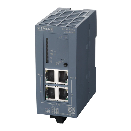
The SCALANCE X204RNA (PRP) has two RJ-45 jacks for connection of end devices or network segments without PRP capability (P1 and P2) and two RJ-45 jacks for connecting to PRP networks LAN A and LAN B (PRP A and PRP B). Figure 4-1 SCALANCE X204RNA (PRP) SCALANCE X-200RNA Operating Instructions, 10/2016, C79000-G8976-C342-04... -
Page 34: Scalance X204Rna (Hsr) Product Characteristics
The SCALANCE X204RNA (HSR) has two RJ-45 jacks for connection of end devices or network segments without HSR capability (P1/A and P2/B) and two RJ-45 jacks for connecting to the "High-availability Seamless Redundancy Protocol" ring (HSR 1 and HSR 2). Figure 4-2 SCALANCE X204RNA (HSR) SCALANCE X-200RNA Operating Instructions, 10/2016, C79000-G8976-C342-04... -
Page 35: Scalance X204Rna Tp Interfaces
With the IE FC cables and IE FC RJ-45 plug 180, an overall cable length of up to 100 m is permitted between two devices depending on the cable type. Note The interfaces of the SCALANCE X204RNA meet the requirements for environment B according to IEEE 802.3, section 33.4.1.1. SCALANCE X-200RNA Operating Instructions, 10/2016, C79000-G8976-C342-04... - Page 36 Please note that the direct connection of two ports on the switch or accidental connection over several switches causes an illegal loop. Such a loop can lead to network overload and network failures. Transmission speed The transmission speed of the Fast Ethernet ports is 100 Mbps full duplex. SCALANCE X-200RNA Operating Instructions, 10/2016, C79000-G8976-C342-04...
-
Page 37: Scalance X204Rna Eec
LAN A and LAN B networks. End devices or network segments without PRP capability are connected to the RJ-45 jacks P1 and P2. Figure 4-4 SCALANCE X204RNA EEC (PRP) SCALANCE X-200RNA Operating Instructions, 10/2016, C79000-G8976-C342-04... -
Page 38: Scalance X204Rna Eec (Prp/Hsr) Product Characteristics
H2 and are intended to connect networks LAN A and LAN B or to connect to the "High- availability Seamless Redundancy Protocol" ring. End devices or network segments without PRP or HSR capability are connected to the RJ-45 jacks 1|1/B and 2|2/B. Figure 4-5 SCALANCE X204RNA EEC (PRP/HSR) SCALANCE X-200RNA Operating Instructions, 10/2016, C79000-G8976-C342-04... -
Page 39: Scalance X204Rna Eec (Hsr) Product Characteristics
"High-availability Seamless Redundancy Protocol" ring. Standard Ethernet end devices or network segments that do not support HSR or networks to be linked are connected to the RJ-45 jacks P1/A and P2/B. Figure 4-6 SCALANCE X204RNA EEC (HSR) SCALANCE X-200RNA Operating Instructions, 10/2016, C79000-G8976-C342-04... -
Page 40: Scalance X204Rna Eec Tp Interfaces
Note The interfaces of the SCALANCE X204RNA EEC (PRP and HSR and PRP/HSR) meet the requirements for environment B according to IEEE 802.3, section 33.4.1.1. SCALANCE X-200RNA Operating Instructions, 10/2016, C79000-G8976-C342-04... - Page 41 Please note that the direct connection of two ports on the switch or accidental connection over several switches causes an illegal loop. Such a loop can lead to network overload and network failures. Transmission speed The transmission speed of the Fast Ethernet ports is 100 Mbps full duplex. SCALANCE X-200RNA Operating Instructions, 10/2016, C79000-G8976-C342-04...
-
Page 42: Scalance X204Rna Eec Sfp Interface
The SFP modules do not ship with the product and must be ordered separately, if needed. Connectors ● Electrical connection: SFP slot ● Optical connection: Duplex LC connector Transmission speed The transmission speed of the optical Fast Ethernet ports is 100 Mbps. SCALANCE X-200RNA Operating Instructions, 10/2016, C79000-G8976-C342-04... - Page 43 Descriptions of the products 4.5 SCALANCE X204RNA EEC Transmission technique The transmission mode for 100Base-FX is specified in the IEEE 802.3 standard. SCALANCE X-200RNA Operating Instructions, 10/2016, C79000-G8976-C342-04...
-
Page 44: C-Plug
Using a previously written C-PLUG If you want to insert a C‑PLUG that has already been used and has been written to in a SCALANCE X-200RNA with a different configuration, the existing C‑PLUG data must first be deleted. Note The devices of the SCALANCE X200RNA product line normally start up with the configuration of the C‑PLUG, assuming this was written to by a compatible device type. - Page 45 C-PLUG are signaled by the diagnostics mechanisms of the devices of the SCALANCE X-200RNA product line (LEDs, SNMP, WBM, etc.). Inserting a C-PLUG The C‑PLUG is not supplied with the SCALANCE X-200RNA. It is available as an optional accessory. The slot for the C-PLUG is located as follows: ●...
-
Page 46: Select/Set Button
The SELECT/SET button is used to switch over the display mode and to make other settings. After turning on the SCALANCE X-200RNA, it is in the display mode. The SELECT/SET button has three functions: ●... - Page 47 On the SCALANCE X204RNA, the SELECT/SET button is located below the C-PLUG compartment. On the SCALANCE X204RNA EEC, the SELECT/SET button is on the top of the device in a recess next to the C-PLUG compartment. SCALANCE X-200RNA Operating Instructions, 10/2016, C79000-G8976-C342-04...
- Page 48 Descriptions of the products 4.7 SELECT/SET button ① C-PLUG ② SELECT/SET button Figure 4-9 Position of the C-PLUG and SELECT/SET button SCALANCE X-200RNA Operating Instructions, 10/2016, C79000-G8976-C342-04...
-
Page 49: Leds
SCALANCE X-200RNA (PRP) 4.8.1.1 Fault LED If the LED is lit red, a SCALANCE X-200RNA (PRP) has detected an error/fault. At the same time, the signaling contact opens assuming that the response of the signaling contact has not been configured differently. -
Page 50: Port Led
4. Setting or display of the fault mask. 4.8.1.4 LED displays during startup When the SCALANCE X-200RNA (PRP) starts up, the following LED displays light up in the order shown: 1. Power LEDs (green) light up immediately after turning on the power. -
Page 51: Mode Led (Scalance X204Rna Eec (Prp/Hsr))
SCALANCE X-200RNA (HSR) 4.8.2.1 Fault LED If the LED is lit red, a SCALANCE X-200RNA (HSR) has detected an error/fault. At the same time, the signaling contact opens assuming that the response of the signaling contact has not been configured differently. -
Page 52: Port Led
4. Setting or display of the fault mask. 4.8.2.4 LED displays during startup When the SCALANCE X-200RNA (HSR) starts up, the following LED displays light up in the order shown: 1. Power LEDs (green) light up immediately after turning on the power. -
Page 53: Mode Led (Scalance X204Rna Eec (Prp/Hsr))
4.8 LEDs 3. Following startup, the correct link status is indicated by the port LEDs after approximately 5 seconds. 4. The SCALANCE X-200RNA (HSR) is now ready for operation. Note SCALANCE X204RNA EEC (PRP/HSR) If the device has not yet been configured, a device error is indicated (red fault LED lit permanently). - Page 54 Descriptions of the products 4.8 LEDs SCALANCE X-200RNA Operating Instructions, 10/2016, C79000-G8976-C342-04...
-
Page 55: Installation
Unless stated otherwise, the mounting options listed below apply to all devices of the type SCALANCE X-200RNA. Note Provide suitable shade to protect SCALANCE X-200RNA devices against direct sunlight. This avoids unwanted warming of devices of the type SCALANCE X‑200RNA and prevents premature aging of the device and cabling. - Page 56 (SCALANCE X204RNA EEC only) of the housing. Minimum clearances If you install the SCALANCE X-200RNA without forced ventilation or cooling, minimum clearances must be maintained to neighboring devices or the wall of the housing. By keeping to the minimum clearances, there is then an adequate stream of air for heat dissipation during operation.
-
Page 57: Mounting On Din Rails
4. Fit the connectors for the signaling contact. 5. Insert the terminal blocks into the sockets on the device. Figure 5-1 Mounting on a 35 mm DIN rail based on the example of a SCALANCE X204RNA EEC SCALANCE X-200RNA Operating Instructions, 10/2016, C79000-G8976-C342-04... - Page 58 5.2 Mounting on DIN rails Fitting the protective bracket ① Hang onto rail at top ② Lock in position below ③ Secure with the screw Figure 5-2 Mounting the protective bracket on the SCALANCE X204RNA EEC SCALANCE X-200RNA Operating Instructions, 10/2016, C79000-G8976-C342-04...
- Page 59 2. Release the DIN rail catch on the bottom of the device using a screwdriver. 3. Then pull the lower part of the device away from the DIN rail. Figure 5-3 Removing from a 35 mm DIN rail based on the example of the SCALANCE X204RNA SCALANCE X-200RNA Operating Instructions, 10/2016, C79000-G8976-C342-04...
-
Page 60: Wall Mounting
To mount the device on a wall, you require the following: ● 2 wall plugs, 6 mm in diameter and 30 mm long ● 2 screws 3.5 mm in diameter and 40 mm long SCALANCE X-200RNA Operating Instructions, 10/2016, C79000-G8976-C342-04... -
Page 61: Wall Mounting
1. Secure an adequately long piece of DIN rail (35 mm) to the wall. 2. Now mount the SCALANCE X-204RNA on the DIN rail as described in the section "DIN rail mounting". See also Mounting on DIN rails (Page 57) Dimension drawings (Page 153) SCALANCE X-200RNA Operating Instructions, 10/2016, C79000-G8976-C342-04... - Page 62 Installation 5.3 Wall mounting SCALANCE X-200RNA Operating Instructions, 10/2016, C79000-G8976-C342-04...
-
Page 63: Connecting Up
L1 +24 VDC Coding of the socket Pin 2 +24 V … +250 VDC 100 V … 240 VAC Coding of the plug Pin 3 Coding of the socket Pin 4 L2 +24 VDC SCALANCE X-200RNA Operating Instructions, 10/2016, C79000-G8976-C342-04... - Page 64 A suitable device is, for example, the Dehn Blitzductor BVT AVD 24 V type no. 918 422 or a comparable protective element. Manufacturer: DEHN+SÖHNE GmbH+Co.KG, Hans-Dehn-Str.1, Postfach 1640, D-92306 Neumarkt, Germany. SCALANCE X-200RNA Operating Instructions, 10/2016, C79000-G8976-C342-04...
- Page 65 Simple grounding via the housing is inadequate. For reliable operation, the PE cable must be connected via the ground bolt. On the SCALANCE X204RNA EEC, the grounding bolt is on the bottom of the device. SCALANCE X-200RNA Operating Instructions, 10/2016, C79000-G8976-C342-04...
-
Page 66: Signaling Contact
The connection or disconnection of a communication node on an unmonitored port does not lead to an error message. The signaling contact remains activated until the error/fault is eliminated or until the current status is applied as the new desired status using the SELECT/SET button. SCALANCE X-200RNA Operating Instructions, 10/2016, C79000-G8976-C342-04... - Page 67 Connecting up 6.2 Signaling contact When the SCALANCE X-200RNA is turned off, the signaling contact is always activated (signals "error/fault"). Note The signaling contact correlates with the red fault LED. Exception: The absence of the power supply is signaled only by the signaling contact (no display by the fault LEDs).
-
Page 68: Sfp Transceiver
Connecting up 6.3 SFP transceiver SFP transceiver The SFP modules are supplied with power via the SFP slot of the SCALANCE X204RNA EEC. SCALANCE X-200RNA Operating Instructions, 10/2016, C79000-G8976-C342-04... -
Page 69: Grounding
Connect the grounding bolt of the device to the nearest grounding point using the grounding cable. To do this use the same wire cross-section as the power supply cable, however not smaller than 1.5 mm²/16 AWG. SCALANCE X-200RNA Operating Instructions, 10/2016, C79000-G8976-C342-04... - Page 70 Connecting up 6.4 Grounding SCALANCE X-200RNA Operating Instructions, 10/2016, C79000-G8976-C342-04...
-
Page 71: Functional Description And Configuration Using Web Based Management
X-200RNA of the product line, you can adapt the configuration of the device to the concrete situation in which it is used. Web Based Management (WBM) accesses the configuration of the SCALANCE X-200RNA using a Web browser. An Ethernet connection to the device is necessary. -
Page 72: Prerequisite
Web Based Management. If a SCALANCE X-200RNA is addressed using a Web browser, it returns HTML pages to the client computer depending on the user input. The user enters the configuration data in the HTML pages sent by the SCALANCE X-200RNA. A SCALANCE X-200RNA evaluates this information and generates reply pages dynamically. - Page 73 2. In the "User name" drop-down list, select the "admin" entry if you want to change settings of the SCALANCE X-200RNA (read and write access). If you select the "User" entry, you only have read access to the configuration data of the SCALANCE X-200RNA.
-
Page 74: Assignment Of An Ip Address
Subnet mask The bits of the host ID can be used to create subnets. The leading bits represent the address of the subnet and the remaining bits the address of the host in the subnet. SCALANCE X-200RNA Operating Instructions, 10/2016, C79000-G8976-C342-04... -
Page 75: Initial Assignment Of An Ip Address
To be able to assign an IP address to the IE switch with the PST, it must be possible to reach the device via Ethernet. You will find the PST on the Internet pages of Siemens Industry Online Support under the following entry ID 19440762 (http://support.automation.siemens.com/WW/view/en/... - Page 76 DHCP request of the IE switch, the IP address, subnet mask and gateway are assigned automatically when the module first starts up. SCALANCE X-200RNA Operating Instructions, 10/2016, C79000-G8976-C342-04...
-
Page 77: Initializing The Scalance X204Rna Eec (Prp/Hsr)
(Exit from CLI/TELNET session) restart (Shutdown and startup again) setmode [PRP|HSR] (Set PRP-/HSR mode and restart) info (Show identification data) SYSTEM (Open SYSTEM menu) X-200 (Open X-200 menu) AGENT (Open AGENT menu) SWITCH (Open SWITCH menu) SCALANCE X-200RNA Operating Instructions, 10/2016, C79000-G8976-C342-04... - Page 78 After you have initialized the SCALANCE X204RNA (PRP/HSR) and restarted the device, the corresponding dialog box is displayed in WBM: Figure 7-3 SCALANCE X204RNA EEC (PRP/HSR) in "PRP" mode Figure 7-4 SCALANCE X204RNA EEC (PRP/HSR) in "HSR" mode SCALANCE X-200RNA Operating Instructions, 10/2016, C79000-G8976-C342-04...
-
Page 79: Led Simulation Of The Wbm
Display of the operating state Each SCALANCE X-200RNA has several LEDs that provide information on the operating state of the device. Depending on its location, direct access to the SCALANCE X-200RNA may not always be possible. Web Based Management therefore displays simulated LEDs. - Page 80 Functional description and configuration using Web Based Management 7.5 LED simulation of the WBM Figure 7-6 LED simulation of the SCALANCE X204RNA SCALANCE X-200RNA Operating Instructions, 10/2016, C79000-G8976-C342-04...
-
Page 81: Working With The Wbm
WEB management is no longer possible. ● Support When you click this link, you open a SIEMENS AG support page. SIEMENS Support is, however, only accessible when your PC has a connection to the Internet. -
Page 82: The "System" Menu
– (p) The setting was made by the Simple Network Time Protocol (SNTP). ● System Up Time (read-only) The time since the last restart. ● "Device Type" (read-only) The type designation of the device. ● "Device Description" (read-only) The type description of the device. SCALANCE X-200RNA Operating Instructions, 10/2016, C79000-G8976-C342-04... -
Page 83: System Identification & Maintenance
The following dialog box contains information on device-specific vendor and maintenance data such as the order number, serial number, version numbers. Figure 7-8 System Identification & Maintenance ● "I&M 0" Here, you can see the individual parameters for Identification & Maintenance. SCALANCE X-200RNA Operating Instructions, 10/2016, C79000-G8976-C342-04... -
Page 84: System Restart & Defaults
7.7.3 System Restart & Defaults Resetting the settings In this menu, you will find a button for restarting the SCALANCE X-200RNA as well as an option for resetting the settings of the SCALANCE X-200RNA. Figure 7-9 System Restart and Defaults... - Page 85 Click the "Restore Factory Defaults and Restart" button to restore the factory default configuration settings. The protected defaults are also reset. An automatic restart is triggered. Note By resetting all the defaults, the IP address is also lost. A SCALANCE X-200RNA can then be accessed using the "Primary Setup Tool". SCALANCE X-200RNA...
-
Page 86: System Save & Load
The WBM allows you to store configuration information in an external file on your client PC or to load such data from an external file from the PC to the SCALANCE X-200RNA. You can also download both new firmware as well as a new FPGA configuration from suitable files on your client PC. - Page 87 Save the configuration data on your computer after you have configured a SCALANCE X-200RNA. Download this file to all other devices of the SCALANCE X-200RNA product line you want to configure. If individual settings are necessary for specific devices, these must be made online.
-
Page 88: System Version Numbers
The version of the firmware is shown here. The hardware version (= product version) is stored permanently on the SCALANCE X-200RNA. ● "FPGA Version" The FPGA version is shown here. ● "Firmware" The version of the firmware running on the SCALANCE X-200RNA. SCALANCE X-200RNA Operating Instructions, 10/2016, C79000-G8976-C342-04... -
Page 89: System Passwords
Functional description and configuration using Web Based Management 7.7 The "System" menu ● "FW Build" The date on which the firmware running on the SCALANCE X-200RNA was created is displayed here. ● "Order Number" The order number of the device is shown here. -
Page 90: System Select/Set Button
You apply your settings with "Set Values". 7.7.7 System SELECT/SET button Configuring the SELECT/SET button On the SCALANCE X-200RNA, the SELECT/SET button is used to ● Change the display mode ● Reset to the factory defaults ● Define the dialog box and the LED display You will find a detailed description of the individual functions available with the button in the section "SELECT/SET button (Page 46)". - Page 91 Figure 7-13 Select/Set button configuration Enable Select/Set Functions You can enable or disable the individual functions of the button by selecting or deselecting the relevant check box. You apply your settings with "Set Values". SCALANCE X-200RNA Operating Instructions, 10/2016, C79000-G8976-C342-04...
-
Page 92: System Event Log Table
System Event Log Table Logging events A SCALANCE X-200RNA allows you to log events and to display them on the page of the "Log Table" menu. This, for example, allows you to record when an SNMP authentication attempt failed or when the connection status of a port has changed. You can specify which events are logged in the "Agent Event Configuration"... -
Page 93: C-Plug Information
7.7.9 C-PLUG Information A SCALANCE X-200RNA allows configuration data to be stored on an external C-PLUG and configuration data to be loaded from an external C-PLUG. The C-PLUG information menu allows you to read out the inserted C-PLUG and to manage configuration data stored on it. - Page 94 Modification of the configuration stored on the C-PLUG. – Copying the current configuration on the C-PLUG with associated restart – Copying the factory configuration to the C-PLUG with associated restart – Deleting the configuration stored on the C-PLUG SCALANCE X-200RNA Operating Instructions, 10/2016, C79000-G8976-C342-04...
-
Page 95: The "X200" Menu
X200 Status Information on the operating status This dialog box appears if you click the "X200" folder icon. The dialog box shows information about the power supply and the error status. Figure 7-16 X200 Status SCALANCE X-200RNA Operating Instructions, 10/2016, C79000-G8976-C342-04... - Page 96 Power supply 2 is not applied or is below the permitted voltage. ● "Fault Status" The fault status of the SCALANCE X-200RNA is shown here. The following table contains examples of possible error messages. If more than one problem has occurred, they are listed in the text box one above the other.
-
Page 97: Prp Configuration
PRP ports is limited to the set value. The limitation can be specified with "Max Throughput". A limitation between 50 and 80% is possible. If the load on the interlinks is greater than the value set, frames are discarded. This occurs regardless of Ethertypes and any VLAN priorities. SCALANCE X-200RNA Operating Instructions, 10/2016, C79000-G8976-C342-04... -
Page 98: Hsr Coupling Configuration
LAN A of a PRP network. P2/B is open and may not be used. Redundant HSR PRP coupling, LAN B Setting with redundant HSR<->PRP coupling. P1/B is con‐ nected with LAN B of a PRP network. P1/A is open and may not be used. SCALANCE X-200RNA Operating Instructions, 10/2016, C79000-G8976-C342-04... -
Page 99: Fault Mask
With the "X200 Fault Mask Power" dialog box, you specify the fault/error states to be monitored by the SCALANCE X-200RNA and that will trigger the signaling contact. Possible fault/error states are the absence of the power supply, power supply too low, or an interrupted connection or an unexpected connection established to a partner device. - Page 100 (line 1 or line 2) or when the voltage is too low (less than 14 V). Note This dialog box is not displayed with the SCALANCE X204RNA EEC because it does not have a redundant power supply. SCALANCE X-200RNA Operating Instructions, 10/2016, C79000-G8976-C342-04...
- Page 101 An error/fault can be signaled in the following ways depending on the configuration of the SCALANCE X-200RNA: Signaling contact, fault LED, SNMP trap, entry in the log table and the syslog.
- Page 102 An error/fault can be signaled in the following ways depending on the configuration of the SCALANCE X-200RNA: Signaling contact, fault LED, SNMP trap, entry in the log table and the syslog. SCALANCE X-200RNA...
-
Page 103: The "Agent" Menu
The "Agent Configuration" dialog box appears if you click the "Agent" folder icon. This dialog box provides you with options for the IP address. You can specify whether a SCALANCE X-200RNA obtains the IP address dynamically or you can assign a fixed address. Figure 7-22 Agent Configuration SCALANCE X-200RNA Operating Instructions, 10/2016, C79000-G8976-C342-04... - Page 104 If you select this option, the configuration data can only be read via DCP (Primary Setup Tool and STEP 7). Agent IP Configuration ● "IP Address" Enter the IP address of the SCALANCE X-200RNA here. ● "Subnet Mask" Enter the subnet mask of the SCALANCE X-200RNA here. ● "Default Gateway"...
-
Page 105: Agent Ping
Functional description and configuration using Web Based Management 7.9 The "Agent" menu Note After changing the IP address, to be able to connect to the SCALANCE X-200RNA again, the new address will need to be entered in the WEB browser manually. 7.9.2 Agent Ping The "Ping"... -
Page 106: Agent Snmp Configuration
Using SNMP (Simple Network Management Protocol), a network management station can configure and monitor SNMP-compliant nodes, such as a SCALANCE X-200RNA. To allow this, a management agent is installed on the SCALANCE X-200RNA with which the management station exchanges data. There are three frame types: ●... - Page 107 Here, you enable / disable SNMPv1/v2c/v3 for a SCALANCE X-200RNA. ● "SNMPv3 Only" Here, you enable / disable SNMPv3 Only for a SCALANCE X-200RNA. ● "Read Only" When this check box is selected, you can only read SNMP variables with SNMPv1/v2c.
-
Page 108: Snmp Trap Configuration
SNMP Trap Configuration SNMP traps for alarm events If an alarm event occurs, a SCALANCE X-200RNA can send traps (alarm frames) to up to 10 different (network management) stations at the same time. Traps are only sent when events as specified in the "Agent Event Configuration" menu occur (see Section "Agent Event Configuration (Page 114)"). -
Page 109: Snmp V3 Groups
It shows all existing SNMPv3 groups. The access rights of these groups can also be found in the table. Figure 7-26 SNMPv3 Groups By clicking the "New Entry" button or clicking on an entry, the "SNMPv3 Group Configuration" dialog box is displayed. SCALANCE X-200RNA Operating Instructions, 10/2016, C79000-G8976-C342-04... - Page 110 By clicking the "Set Values" button, you create a group according to the parameters set above. ● "Current Entries" By clicking the "Current Entries" button, you exit the "SNMPv3 Group Configuration" dialog box and return to the "SNMPv3 Groups" dialog box. SCALANCE X-200RNA Operating Instructions, 10/2016, C79000-G8976-C342-04...
-
Page 111: Snmp V3 User
It shows all existing SNMPv3 users. You can also see the groups to which the user belongs and the security level of the user in the table. Figure 7-28 SNMPv3 Users By clicking the "New Entry" button or clicking on an entry, the "SNMPv3 Users Configuration" dialog box is displayed. SCALANCE X-200RNA Operating Instructions, 10/2016, C79000-G8976-C342-04... - Page 112 By clicking the "Set Values" button, you create a user according to the parameters set above. ● "Current Entries" By clicking the "Current Entries" button, you exit the "SNMPv3 Users Configuration" dialog box and return to the "SNMPv3 Users" dialog box. SCALANCE X-200RNA Operating Instructions, 10/2016, C79000-G8976-C342-04...
-
Page 113: Agent Timeout Configuration
Permitted values for the WBM timeout: 0 ... 3600 (seconds) 0 means: There is no automatic logout. ● "CLI (TELNET, SSH, Serial) (sec)" Here, you specify the CLI timeout. Permitted values for the CLI timeout: 60 ... 600 (seconds) SCALANCE X-200RNA Operating Instructions, 10/2016, C79000-G8976-C342-04... -
Page 114: Agent Event Configuration
Agent Event Configuration System events of the SCALANCE X-200RNA On this page, you specify how a SCALANCE X-200RNA reacts to system events. By enabling the appropriate check boxes, you specify which events trigger which reactions on the SCALANCE X-200RNA. The following options are available: ●... - Page 115 Functional description and configuration using Web Based Management 7.9 The "Agent" menu ● The SCALANCE X-200RNA writes an entry in the log file. ● The SCALANCE X-200RNA writes an entry to the Syslog server. Figure 7-31 Agent Event Configuration with the SCALANCE X204RNA EEC...
- Page 116 7.9 The "Agent" menu Figure 7-32 Agent Event Configuration with the SCALANCE X204 RNA You can configure the reaction of the SCALANCE X-200RNA to the following events: ● "Cold / Warm Start" The SCALANCE X-200RNA was turned on or restarted by the user.
-
Page 117: Agent E-Mail Configuration
– If a PRP B frame is received at PRP A or vice versa, the error is set until no more incorrect frames are received for approximately 30 seconds. 7.9.9 Agent E-Mail Configuration Setting the e-mail client Here, you can set the recipient, sender and the SMTP server. Figure 7-33 Agent E-Mail Configuration SCALANCE X-200RNA Operating Instructions, 10/2016, C79000-G8976-C342-04... -
Page 118: Agent Syslog Configuration
Enter, the port of the SMTP server. ● ""From"-Field" Here, enter the e-mail address of the sender. 7.9.10 Agent Syslog Configuration Setting the Syslog server Here, you can specify the address of the Syslog server. Figure 7-34 Agent Syslog Configuration SCALANCE X-200RNA Operating Instructions, 10/2016, C79000-G8976-C342-04... -
Page 119: Agent Dhcp Configuration
Enter, the port of the Syslog server. 7.9.11 Agent DHCP Configuration Setting the DHCP mode There are several ways of identifying the SCALANCE X-200RNA in the configuration of the DHCP server: ● with the MAC address ● with a freely defined client ID... - Page 120 "disabled" is displayed. ● "DHCP Client ID" For the DHCP mode "via Client ID", you can assign an identification string here that is assigned to a SCALANCE X-200RNA and will be evaluated by the DHCP server. SCALANCE X-200RNA Operating Instructions, 10/2016, C79000-G8976-C342-04...
-
Page 121: Agent Time Configuration
SNTP (Simple Network Time Protocol) is used for synchronizing the time in the network. The appropriate frames are sent by an SNTP server in the network. A SCALANCE X-200RNA logs on as client with this server as recipient of time-of-day frames. - Page 122 There is no standard/daylight-saving time switchover on the SCALANCE X-200RNA. ● "Init Poll Interval" Here, you can enter the interval at which a SCALANCE X-200RNA repeats the poll when the system time is initially set, if this was not successful the first time. ● "Poll Interval"...
-
Page 123: The "Switch" Menu
7.10.2 Switch Config Switch functionality The "Switch Configuration" dialog box appears if you click the "Switch" folder icon. In this dialog box, you specify the aging time of the SCALANCE X-200RNA. Figure 7-37 Switch Configuration SCALANCE X-200RNA Operating Instructions, 10/2016, C79000-G8976-C342-04... -
Page 124: Port Status
Aging prevents frames being forwarded incorrectly, for example when an end device (for example a programming device) is connected to a different switch port. If the check box is not enabled, a SCALANCE X-200RNA does not delete learnt addresses automatically. -
Page 125: Switch Forwarding Database
● "Negotiation" Indicates whether or not autonegotiation is enabled. Note Since the SCALANCE X-200RNA supports only 100 Mbps Ethernet in full duplex mode, autonegotiation is always enabled. ● "Active" Indicates whether or not the port is turned on (true). Data traffic is possible only over an enabled port. - Page 126 Shows whether the MAC address is listed as a source MAC address in the duplicate filter table. ● "Proxy Node" Shows whether the MAC address is listed as a source MAC address in the proxy node table. SCALANCE X-200RNA Operating Instructions, 10/2016, C79000-G8976-C342-04...
-
Page 127: The Statistics Menu
Received frames sorted by length The "Packet Size Statistic" dialog box displays how many packets of which size were received at each port. If you click the "Reset Counters" button, you reset this counter for all ports. SCALANCE X-200RNA Operating Instructions, 10/2016, C79000-G8976-C342-04... - Page 128 There is a separate element in the graphic for each of the following ranges: ● 64 bytes ● 65 - 127 bytes ● 128 -255 bytes ● 256 - 511 bytes SCALANCE X-200RNA Operating Instructions, 10/2016, C79000-G8976-C342-04...
-
Page 129: Packet Type Statistic
7.10.7 Packet Type Statistic Received frames sorted by type The "Packet Type Statistic" dialog box displays how many frames of the type unicast, multicast, and broadcast were received and sent at each port. SCALANCE X-200RNA Operating Instructions, 10/2016, C79000-G8976-C342-04... - Page 130 This dialog box displays the number of frames received at each port graphically. The display depends on the packet type. There is a separate element in the graphic for each of the following ranges: ● Unicast ● Multicast ● Broadcast SCALANCE X-200RNA Operating Instructions, 10/2016, C79000-G8976-C342-04...
- Page 131 When the percentage is calculated, packet types are included only if their check boxes are selected. With the "Previous Port" and "Next Port" buttons, you can change to the display of the previous or next port. SCALANCE X-200RNA Operating Instructions, 10/2016, C79000-G8976-C342-04...
-
Page 132: Packet Error Statistic
Number of frames that were discarded at the receiving port due to lack of resources on the switch. If you click the "Reset Counters" button, you reset this counter for all ports. Figure 7-44 Packet Error Statistic SCALANCE X-200RNA Operating Instructions, 10/2016, C79000-G8976-C342-04... - Page 133 When the percentage is calculated, error types are included only if their check boxes are selected. With the "Previous Port" and "Next Port" buttons, you can change to the display of the previous or next port. SCALANCE X-200RNA Operating Instructions, 10/2016, C79000-G8976-C342-04...
-
Page 134: Prp Statistic
● "Received A Frames at PRP B Port" Number of A frames received at port PRP B (error). If you click the "Reset Counters" button, you reset this counter for all ports. Figure 7-46 PRP Statistic SCALANCE X-200RNA Operating Instructions, 10/2016, C79000-G8976-C342-04... -
Page 135: Redundancy Statistic
Number of valid HSR frames that were received at port P1/A (error). ● Received HSR Frames at Port P2/B Number of valid HSR frames that were received at port P2/B (error). If you click the "Reset Counters" button, you reset this counter for all ports. SCALANCE X-200RNA Operating Instructions, 10/2016, C79000-G8976-C342-04... - Page 136 Functional description and configuration using Web Based Management 7.10 The "Switch" menu Figure 7-47 Redundancy Statistic SCALANCE X-200RNA Operating Instructions, 10/2016, C79000-G8976-C342-04...
-
Page 137: Approvals And Marking
Example German: "EG Konformitätserklärung SCALANCE X204RNA", Example English: "Declaration of Conformity SCALANCE X204RNA ". EMC directive (electromagnetic compatibility) The devices of the type SCALANCE X-200RNA meet the requirements of the EC directive: 2004/108/EEC "Electromagnetic Compatibility" The product is designed for use in the following areas:... - Page 138 The current descriptions of the currently available products can always be found on the Internet under the specified Internet pages: – SIMATIC NET Industrial Twisted Pair and Fiber Optic Networks (http:// support.automation.siemens.com/WW/view/en/8763736/) , Manual – EMC Installation Guideline (http://support.automation.siemens.com/WW/view/en/ 60612658), Configuration manual ●...
- Page 139 The product meets the requirements of the Korea Certification. UL Approval for Information Technology Equipment Underwriters Laboratories (UL) complying with Standard UL 60950-1 UL Approval for Industrial Control Equipment Underwriters Laboratories (UL) complying with Standard UL 508 SCALANCE X-200RNA Operating Instructions, 10/2016, C79000-G8976-C342-04...
- Page 140 GP. IIC, T.. 0145X Ta:.. X204RNA EEC UL 508 FM 3611 AS/NZS Korea Certifi‐ 61000-6-4, 2064 cation CL.1, Div.2 (Class A). C22.2 GP. A.B.C.D EN 61000-6-2 No. 142- M1987 CL.1, Zone 2, GP. IIC, T.. Ta:.. SCALANCE X-200RNA Operating Instructions, 10/2016, C79000-G8976-C342-04...
- Page 141 You will find the hardware version of your device on the type plate. On the type plate, the hardware version is printed as a placeholder “X”. Example: X 2 3 4 5 6 In this case, "X" would be the placeholder for hardware version 1. SCALANCE X-200RNA Operating Instructions, 10/2016, C79000-G8976-C342-04...
- Page 142 Approvals and marking SCALANCE X-200RNA Operating Instructions, 10/2016, C79000-G8976-C342-04...
-
Page 143: Technical Specifications
[19.2 .. 300 VDC] 150 mA at 100 VAC 250 mA at 24 VDC 1x 240 VDC (50/60 Hz) Overvoltage category II (100 .. 240 VAC) [85 .. 276 VAC] SCALANCE X-200RNA Operating Instructions, 10/2016, C79000-G8976-C342-04... -
Page 144: Technical Specifications
SFP module SFP991-1 SFP module SFP991-1LD SFP module SFP991-1LH+ Table 9-7 Degree of protection and MTBF Device type Degree of protection MTBF SCALANCE X204RNA IP20 92.45 years X204RNA EEC IP20 67.64 years SCALANCE X-200RNA Operating Instructions, 10/2016, C79000-G8976-C342-04... - Page 145 Note Note the orientation of the installed SCALANCE X204RNA and X204RNA EEC If a SCALANCE X204RNA or X204RNA EEC is mounted on a vertical rail, an ambient temperature of maximum +40 °C is permitted. SCALANCE X-200RNA Operating Instructions, 10/2016, C79000-G8976-C342-04...
- Page 146 Technical specifications SCALANCE X-200RNA Operating Instructions, 10/2016, C79000-G8976-C342-04...
-
Page 147: Accessories And Compatible Devices
IE FC outlet RJ-45 6GK1901-1FC00-0AA0 TP cord RJ-45/RJ-45 0.5 m 6XV1870-3QE30 1.0 m 6XV1870-3QH10 2.0 m 6XV1870-3QH20 6.0 m 6XV1870-3QH60 10 m 6XV1870-3QN10 SFP module SFP991-1 multimode glass up to 3 km 6GK5991-1AD00-8AA0 SCALANCE X204RNA EEC SCALANCE X-200RNA Operating Instructions, 10/2016, C79000-G8976-C342-04... - Page 148 SM robust cable (4x19/125) (900 µm) 6XV1843-2R SCALANCE X204RNA EEC MM LC duplex plug 6GK1 901-0RB10-2AB0 SCALANCE X204RNA EEC SM LC duplex plug 6GK1 901-0SB10-2AB0 SCALANCE X204RNA EEC Other hardware C-PLUG 6GK1900-0AB00 X-200RNA Software SOFTNET-IE RNA 6GK1711-1EW12-0AA0 SCALANCE X-200RNA Operating Instructions, 10/2016, C79000-G8976-C342-04...
-
Page 149: Prp-Compatible Devices
SCALANCE X204IRT, managed IE switch 6GK5204-0BA00-2BA3 V1.0 SCALANCE XF204IRT, managed IE switch 6GK5204-0BA00-2BF2 V1.0 SCALANCE X204IRT PRO 6GK5204-0JA00-2BA6 V1.0 SCALANCE X204-2, managed IE switch 6GK5204-2BB10-2AA3 V4.4 SCALANCE X204-2TS, managed IE switch 6GK5204-2BB10-2CA2 V4.4 SCALANCE X204RNA 6GK5204-0BA00-2KB2 V1.0 SCALANCE X-200RNA Operating Instructions, 10/2016, C79000-G8976-C342-04... - Page 150 SCALANCE X307-2EEC,24 VDC redundant power supply unit; 6GK5307-2FD00-2GA3 V3.7.0 CONFORMAL COATING SCALANCE X307-2EEC, 100 ... 240 VAC/VDC power supply unit 6GK5307-2FD00-3EA3 V3.7.0 SCALANCE X307-2EEC, 100 ... 240 VAC/VDC power supply unit; 6GK5307-2FD00-3GA3 V3.7.0 CONFORMAL COATING SCALANCE X-200RNA Operating Instructions, 10/2016, C79000-G8976-C342-04...
- Page 151 6GK5324-0GG00-1CR2 V3.7.2 outlet front SCALANCE X408-2, modular IE switch 6GK5408-2FD00-2AA2 V3.7.0 SCALANCE X414-3E, modular IE switch 6GK5414-3FC00-2AA2 V3.7.0 COMPACT SWITCH MODULE CSM 1277 6GK7277-1AA10-0AA0 ES: 01 COMPACT SWITCH MODULE CSM 377 6GK7377-1AA00-0AA0 ES: 01 SCALANCE X-200RNA Operating Instructions, 10/2016, C79000-G8976-C342-04...
- Page 152 Seamless Redundancy Protocol" (HSR) is used. Only devices equipped with HSR interfaces can be used in HSR rings.. Devices without HSR capability, must be connected to the HSR ring by an HSR version of the SCALANCE X-200RNA. SCALANCE X-200RNA Operating Instructions, 10/2016, C79000-G8976-C342-04...
-
Page 153: Dimension Drawings
Dimension drawings Figure 11-1 SCALANCE X204RNA, front view SCALANCE X-200RNA Operating Instructions, 10/2016, C79000-G8976-C342-04... -
Page 154: Dimension Drawings
Dimension drawings Figure 11-2 SCALANCE X204RNA, side view SCALANCE X-200RNA Operating Instructions, 10/2016, C79000-G8976-C342-04... - Page 155 Dimension drawings Figure 11-3 SCALANCE X204RNA EEC, front view SCALANCE X-200RNA Operating Instructions, 10/2016, C79000-G8976-C342-04...
- Page 156 Dimension drawings Figure 11-4 SCALANCE X204RNA EEC, side view SCALANCE X-200RNA Operating Instructions, 10/2016, C79000-G8976-C342-04...
-
Page 157: Index
Bad Frames, 132 Parallel Redundancy Protocol, 18 CRC, 132 Dropped L2, 132 Oversize, 132 Undersize, 132 Ping, 105 Port Port configuration, 124 Possible attachments Factory Defaults, 85 SCALANCE X204RNA EEC, 37 Fault mask, 99 SCALANCE X-200RNA Operating Instructions, 10/2016, C79000-G8976-C342-04... - Page 158 Switch Forwarding Database, 125 Syslog, 104, 119 TELNET, 104 Time of day SNTP (Simple Network Time Protocol), 121 Time zone, 122 Time-of-day synchronization, 121 UTC time, 122 Time zone, 122 Timeout, 113 Training, 10 SCALANCE X-200RNA Operating Instructions, 10/2016, C79000-G8976-C342-04...