Table of Contents
Advertisement
Quick Links
SIMATIC NET
Industrial Ethernet switches
SCALANCE XM-400
Operating Instructions
03/2021
C79000-G8976-C306-10
Introduction
Safety notices
Recommendations on
network security
Description of the device
Installation
Connecting up
Upkeep and maintenance
Technical specifications
Dimension drawings
Approvals
1
2
3
4
5
6
7
8
9
A
Advertisement
Table of Contents

Related Manuals for Siemens SIMATIC NET SCALANCE XM-400 Series


Summary of Contents for Siemens SIMATIC NET SCALANCE XM-400 Series
- Page 1 Introduction Safety notices Recommendations on network security SIMATIC NET Description of the device Industrial Ethernet switches SCALANCE XM-400 Installation Connecting up Operating Instructions Upkeep and maintenance Technical specifications Dimension drawings Approvals 03/2021 C79000-G8976-C306-10...
- Page 2 Note the following: WARNING Siemens products may only be used for the applications described in the catalog and in the relevant technical documentation. If products and components from other manufacturers are used, these must be recommended or approved by Siemens. Proper transport, storage, installation, assembly, commissioning, operation and maintenance are required to ensure that the products operate safely and without any problems.
-
Page 3: Table Of Contents
Table of contents Introduction ............................5 Safety notices ............................11 Recommendations on network security ....................13 Description of the device ........................19 Properties and functions ....................19 Product overview ....................... 21 Accessories ........................23 Spare parts ........................27 Device views ........................28 4.5.1 SCALANCE XM408-4C ...................... - Page 4 Table of contents Connecting up ............................. 53 Safety when connecting up....................53 Spring-loaded terminal....................... 56 Power supply ........................57 Signaling contact ....................... 59 Serial interface........................61 Out-of-band interface ......................63 Functional ground ......................64 Upkeep and maintenance........................65 Downloading new firmware using TFTP without WBM and CLI..........65 Restoring the factory settings.....................
-
Page 5: Introduction
Introduction Purpose of the Operating Instructions These operating instructions support you when installing and connecting up devices of the SCALANCE XM-400 product group. The configuration and the integration of the device in a network are not described in these operating instructions. Validity of the Operating Instructions These operating instructions apply to the following devices: •... - Page 6 • On the Internet pages of Siemens Industry Online Support (https:// support.industry.siemens.com/cs/ww/en/ps/15315) When using the Function Extender BUS ANALYZER Agent XM-400, note the documentation of the BUS ANALYZER Agent XM-400 on the Siemens Industry Online Support website: • Product announcement (https://support.industry.siemens.com/cs/de/en/view/109745817) • Application example (https://support.industry.siemens.com/cs/de/en/view/109762541) Documentation on configuration...
- Page 7 • On the Internet under the following address: 50305045 (https://support.industry.siemens.com/cs/ww/en/view/50305045) Security information Siemens provides products and solutions with industrial security functions that support the secure operation of plants, systems, machines and networks. In order to protect plants, systems, machines and networks against cyber threats, it is necessary to implement –...
- Page 8 (https://www.siemens.com/industrialsecurity) Catalogs You will find the article numbers for the Siemens products of relevance here in the following catalogs: • SIMATIC NET Industrial Communication / Industrial Identification, catalog IK PI • SIMATIC Products for Totally Integrated Automation and Micro Automation, catalog ST 70 •...
- Page 9 Introduction Trademarks The following and possibly other names not identified by the registered trademark sign ® registered trademarks of Siemens AG: SIMATIC NET, SCALANCE, C-PLUG, OLM SCALANCE XM-400 Operating Instructions, 03/2021, C79000-G8976-C306-10...
- Page 10 Introduction SCALANCE XM-400 Operating Instructions, 03/2021, C79000-G8976-C306-10...
-
Page 11: Safety Notices
Safety notices Read the safety notices Note the following safety notices. These relate to the entire working life of the device. You should also read the safety notices relating to handling in the individual sections, particularly in the sections "Installation" and "Connecting up". CAUTION To prevent injury, read the manual before use. - Page 12 Safety notices SCALANCE XM-400 Operating Instructions, 03/2021, C79000-G8976-C306-10...
-
Page 13: Recommendations On Network Security
• Evaluate your plant as a whole in terms of security. Use a cell protection concept with suitable products (https://www.industry.siemens.com/topics/global/en/industrial-security/pages/ default.aspx). • When the internal and external network are disconnected, an attacker cannot access internal data from the outside. Therefore operate the device only within a protected network area. - Page 14 Industrial Security (https://www.siemens.com/ industrialsecurity) website. • Inform yourself regularly about security recommendations published by Siemens ProductCERT (https://www.siemens.com/cert/en/cert-security-advisories.htm). • Only activate protocols that you require to use the device. • Restrict access to the management of the device with rules in an access control list (ACL).
- Page 15 Recommendations on network security Secure/non-secure protocols and services • Avoid or disable non-secure protocols and services, for example HTTP, Telnet and TFTP. For historical reasons, these protocols are available, however not intended for secure applications. Use non-secure protocols on the device with caution. •...
- Page 16 Recommendations on network security Available protocols The following list provides you with an overview of the open protocol ports. The table includes the following columns: • Protocol • Port • Default port status – Open The factory setting of the port is "Open". –...
- Page 17 Recommendations on network security Protocol Protocol/ Default port status Configurable port Authentication Encryption Port number RADIUS UDP/ Closed ✓ 1812,1813 UDP/520 Closed RIPng IPv6 UDP/521 Closed ✓ SMTP TCP/25 Closed ✓ TCP/465 SNMP UDP/161 Open ✓ Yes (when config‐ ured) TCP/22 Open ✓...
- Page 18 Recommendations on network security SCALANCE XM-400 Operating Instructions, 03/2021, C79000-G8976-C306-10...
-
Page 19: Description Of The Device
Description of the device Properties and functions SCALANCE XM-400 product group The product group SCALANCE XM-400 consists of basic devices (compact switches) and extenders (port extenders and function extender). SCALANCE XM-400 basic device Basic properties The SCALANCE XM-400 basic devices are modular compact switches with fixed RJ-45 ports (10/100/1000 Mbps) and SFP transceiver slots that can be equipped individually. - Page 20 Description of the device 4.1 Properties and functions Port extender PE-400 Port extenders are modular network components with RJ-45 ports (10/100/1000 Mbps) or SFP transceiver slots. To the left they have an expansion interface to connect to the basic device or to another port extender and to the right they have an expansion interface for additional port extenders.
-
Page 21: Product Overview
Description of the device 4.2 Product overview Product overview Article numbers Type Properties Article number SCALANCE XM408-4C 8 RJ-45 ports, 4 pluggable transceiver slots, up to 2 port extenders and 1 6GK5 function extender, layer 3 with KEY-PLUG 408-4GP00-2AM2 8 RJ-45 ports, 4 pluggable transceiver slots, up to 2 port extenders and 1 6GK5 function extender, layer 3 integrated 408-4GQ00-2AM2... - Page 22 Description of the device 4.2 Product overview Unpacking and checking WARNING Do not use any parts that show evidence of damage If you use damaged parts, there is no guarantee that the device will function according to the specification. If you use damaged parts, this can lead to the following problems: •...
-
Page 23: Accessories
Description of the device 4.3 Accessories Accessories The following accessories are available for SCALANCE XM-400: KEY-PLUG Type Article number KEY-PLUG XM400 Layer 3 6GK5 904-0PA00 See also Technical specifications (Page 67) C-PLUG Component Description Article number C-PLUG Configuration plug, exchangeable storage medium for con‐ 6GK1 900-0AB00 figuration data, 32 MB Configuration plug, exchangeable storage medium for con‐... - Page 24 Description of the device 4.3 Accessories Pluggable transceiver SFP (1000 Mbps) Type Property Article number SFP992-1 1 x 1000 Mbps, LC port optical for glass FO cable 6GK5 992-1AL00-8AA0 (multimode), up to max. 750 m 10 packing unit (VPE 10) 6GK5 992-1AL00-8AC0 SFP992-1 (C) 1 x 1000 Mbps, LC port optical, for glass FO cable...
- Page 25 Description of the device 4.3 Accessories Bidirectional plug-in transceiver SFP Bidirectional plug-in transceivers feature only one fiber connection. They transmit and receive on two different wavelengths. To establish a connection, you need two matching bidirectional SFPs. The connected SFPs must respectively transmit on the wavelength at which the connection partner receives.
- Page 26 Description of the device 4.3 Accessories Type Properties Article number STP991-1 1 x 100 Mbps ST port optical for glass FO cable (mul‐ 6GK5 991-1AB00-8AA0 timode) up to max. 3 km STP991-1LD 1 x 100 Mbps ST port optical for glass FO cable (sin‐ 6GK5 991-1AC00-8AA0 gle mode) up to max.
-
Page 27: Spare Parts
Description of the device 4.4 Spare parts Spare parts The following spare parts are available for SCALANCE XM-400: Component Description Article number C-PLUG Configuration plug, 6GK1 900-0AB00 exchangeable storage medium for configuration data Spring-loaded terminal block, 4 4-terminal spring-loaded terminal block to connect the power 6GK5 980-1DB10-0AA5 terminals supply (24 VDC),... -
Page 28: Device Views
Description of the device 4.5 Device views Device views 4.5.1 SCALANCE XM408-4C The following figure shows an overview of the components of the SCALANCE XM408-4C. ① Electrical ports ② Expansion interface with cover ③ Slots for pluggable transceivers (STP and DCP) ④... -
Page 29: Scalance Xm408-8C
Description of the device 4.5 Device views 4.5.2 SCALANCE XM408-8C The following figure shows an overview of the components of the SCALANCE XM408-8C. ① Electrical ports ② Expansion interface with cover ③ Slots for SFP transceivers ④ Location for securing to an S7 standard rail (on the underside of the device, not in figure) ⑤... -
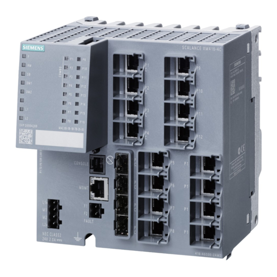
Page 30: Scalance Xm416-4C
Description of the device 4.5 Device views 4.5.3 SCALANCE XM416-4C The following figure shows an overview of the components of the SCALANCE XM416-4C. ① Electrical ports ② Expansion interface with cover ③ Slots for SFP transceivers ④ Location for securing to an S7 standard rail (on the underside of the device, not in figure) ⑤... -
Page 31: Select / Set Button
Description of the device 4.6 SELECT / SET button SELECT / SET button Position The "SELECT/SET" button is located on the front of the SCALANCE XM-400. Figure 4-1 Position of the "SELECT/SET" button on the SCALANCE XM-400 Setting the display mode To set the required display mode, press the "SELECT/SET"... - Page 32 Description of the device 4.6 SELECT / SET button Requirement • The device is in operation. • The function "Restore Factory Defaults" is enabled for the "SELECT / SET" button. Note Reset despite disabled "SELECT/SET" button If you have disabled the "Restore Factory Defaults" function for the "SELECT/SET" button in the configuration, this does not apply during the startup phase, see section "Restoring the factory settings (Page 66)".
-
Page 33: Led Display
Description of the device 4.7 LED display LED display 4.7.1 Overview The following figure shows the arrangement of the LEDs. LED for displaying the fault/error status LED for displaying the "redundancy manager" function LED for display of redundantly linked rings DM1/DM2 LEDs for displaying the display mode L1/L2... -
Page 34: Sb" Led
Description of the device 4.7 LED display 4.7.3 "SB" LED With a redundant linking of rings, the "SB" LED shows the status of the redundant connection. The available options of a redundant link are as follows: • Standby Function • MRP Interconnection Standby Function LED color LED status... -
Page 35: Leds "L1" And "L2
Description of the device 4.7 LED display There are 5 display modes (A, B, C, D, and E). Display mode A is the default mode. Depending on the set display mode, the "L1", "L2" LEDs and the port LEDs show different information. -
Page 36: Port Leds
Description of the device 4.7 LED display Meaning in display mode D In display mode D, the "L1" and "L2" LEDs indicate whether the power supply is monitored. L1/L2 LED L1/L2 connector LED color LED status Power supply is not monitored. If the power supply falls below 17 V, the signaling contact does not respond. - Page 37 Description of the device 4.7 LED display Mbps) continues to be displayed. If there is a connection problem and auto negotiation is active, the port LED goes off. Meaning in display mode C In display mode C, the port LEDs indicate the mode. LED color LED status Meaning...
-
Page 38: C-Plug/Key-Plug
Description of the device 4.8 C-PLUG/KEY-PLUG C-PLUG/KEY-PLUG 4.8.1 Function of the C-PLUG/KEY-PLUG NOTICE Do not remove or insert a C-PLUG/KEY-PLUG during operation A C-PLUG/KEY-PLUG may only be removed or inserted when the device is turned off. Saving configuration data and enabling layer 3 functionality A PLUG is an exchangeable storage medium for storing the configuration data of the device. -
Page 39: Replacing The C-Plug/Key-Plug
Description of the device 4.8 C-PLUG/KEY-PLUG Operation with C-PLUG/KEY-PLUG The configuration stored on the C-PLUG/KEY-PLUG is displayed via the user interfaces. If changes are made to the configuration, the device stores the configuration directly on the C- PLUG/KEY-PLUG, if this is in the "ACCEPTED" status. The internal memory is neither read nor written. - Page 40 Description of the device 4.8 C-PLUG/KEY-PLUG Replacing a C-PLUG/KEY-PLUG Removing a C-PLUG/KEY-PLUG 1. Turn off the power to the device. 2. Insert a screwdriver between the front edge of the C-PLUG/KEY-PLUG (A) and the slot and release the C-PLUG/KEY-PLUG. 3. Remove the C-PLUG/KEY-PLUG. Inserting a C-PLUG/KEY-PLUG 1.
-
Page 41: Functions
Description of the device 4.9 Functions Functions 4.9.1 Combo ports Characteristics Combo port is the name for two communication ports. A combo port has the two following jacks: • a fixed RJ-45 port • an SFP transceiver slot that can be equipped individually Of these two ports, only one can ever be active. - Page 42 You will find the Operating Instructions here: • On the data medium that ships with some products: – Product CD / product DVD – SIMATIC NET Manual Collection • On the Internet pages of Siemens Industry Online Support (http:// support.automation.siemens.com/WW/view/en/79730528/133300) SCALANCE XM-400...
-
Page 43: Installation
Installation Safety notices for installation Safety notices When installing the device, keep to the safety notices listed below. WARNING If a device is operated in an ambient temperature of more than 50 °C, the temperature of the device housing may be higher than 70 °C. The device must therefore be installed so that it is only accessible to service personnel or users that are aware of the reason for restricted access and the required safety measures at an ambient temperature higher than 50 °C. - Page 44 Installation 5.1 Safety notices for installation Safety notices for use according to ATEX and IECEx If you use the device under ATEX or IECEx conditions you must also keep to the following safety notices in addition to the general safety notices for protection against explosion: WARNING To comply with EC Directive 2014/34/EU (ATEX 114) or the conditions of IECEx, this enclosure or cabinet must meet the requirements of at least IP54 in compliance with EN 60529.
-
Page 45: Types Of Installation
Installation 5.2 Types of installation Types of installation Types of installation You have the following options for the device: • DIN rail • S7-300 standard rail • S7-1500 standard rail Installation clearance Observe the following minimum clearances so that the convection ventilation of the device is not blocked: •... -
Page 46: Mounting On Din Rails
Installation 5.3 Mounting on DIN rails Mounting on DIN rails Installation WARNING Danger of injury by falling objects The 35 mm DIN rail does not provide adequate support in shipping or when there is severe vibration (> 10 g). When used under these conditions, the device can detach itself and may cause injury to persons. -
Page 47: Installation On A Standard S7-300 Rail
Installation 5.4 Installation on a standard S7-300 rail Installation on a standard S7-300 rail Installing on an S7-300 standard rail Figure 5-2 S7-300 standard rail mounting To screw the device to an S7-300 standard rail, you require a securing screw with the following properties: •... -
Page 48: Installation On A Standard S7-1500 Rail
Installation 5.5 Installation on a standard S7-1500 rail Installation on a standard S7-1500 rail Installing on an S7-1500 standard rail Figure 5-3 S7-1500 standard rail mounting To screw the device to an S7-1500 standard rail, you require a securing screw with the following properties: •... -
Page 49: Fitting An Extender
Installation 5.6 Fitting an extender Fitting an extender Position The following figure shows the elements required to connect two devices. ① Locking mechanism (on the rear of the device) ② Centering pin ③ Multipole connector for connection to the expansion interface ④... - Page 50 Installation 5.6 Fitting an extender Fitting and removing an extender Fitting an extender To fit an extender, follow the steps below: 1. Remove the cover of the expansion interface on the basic device. 2. Fit the two devices together so that the two centering pins are accommodated by the ①...
- Page 51 Installation 5.6 Fitting an extender Exchanging extenders - with change of medium Exchanging extenders If you replace an electrical extender with an optical extender (or vice versa), this can lead to malfunctions. The IE switch therefore reacts as follows: • The extender is disabled. •...
-
Page 52: General Notes For Sfp Transceivers
WARNING Use only approved SFP transceivers If you use SFP transceivers that have not been approved by Siemens AG, there is no guarantee that the device will function according to its specifications. If you use unapproved SFP transceivers, this can lead to the following problems: •... -
Page 53: Connecting Up
Connecting up Safety when connecting up Safety notices When connecting up the device, keep to the safety notices listed below. WARNING The equipment is designed for operation with Safety Extra-Low Voltage (SELV) by a Limited Power Source (LPS). This means that only SELV / LPS complying with IEC 60950-1 / EN 60950-1 / VDE 0805-1 must be connected to the power supply terminals, or the power supply unit for the equipment power supply must comply with NEC Class 2, as described by the National Electrical Code (r) (ANSI / NFPA 70). - Page 54 Connecting up 6.1 Safety when connecting up Safety notices on use in hazardous areas General safety notices relating to protection against explosion WARNING EXPLOSION HAZARD Do not connect or disconnect cables to or from the device when a flammable or combustible atmosphere is present.
- Page 55 Connecting up 6.1 Safety when connecting up Further notes WARNING Commissioning devices and replacement devices If you use redundancy mechanisms (HRP/MRP ring redundancy and/or redundant coupling of rings with standby), open the redundant path before you insert a new or replacement device in an operational network.
-
Page 56: Spring-Loaded Terminal
Connecting up 6.2 Spring-loaded terminal Spring-loaded terminal The following figure shows the individual components of a spring-loaded terminal: ① Wire inlet For connecting the wire ② Button For releasing the wire ③ Test contact For measuring the voltage SCALANCE XM-400 Operating Instructions, 03/2021, C79000-G8976-C306-10... -
Page 57: Power Supply
Connecting up 6.3 Power supply Power supply Notes on the power supply WARNING Incorrect power supply If the device is connected to a redundant power supply (two separate power supplies), both must meet these requirements. Never operate the device with AC voltage or DC voltage higher than 32 V DC. CAUTION Damage to the device due to overvoltage The connector of the external power supply is not protected against strong electromagnetic... - Page 58 Connecting up 6.3 Power supply Position and assignment Figure 6-1 Position of the power supply on the SCALANCE XM-400 and the assignment of the terminal block Contact Assignment 24 VDC Ground Ground 24 VDC SCALANCE XM-400 Operating Instructions, 03/2021, C79000-G8976-C306-10...
-
Page 59: Signaling Contact
Connecting up 6.4 Signaling contact Signaling contact Information on the signaling contact • The signaling contact is a floating switch that signals error statuses by opening the contact. The signaling contact must be operated within the range of the operating voltage. If an error/fault occurs, the signaling contact opens. - Page 60 Connecting up 6.4 Signaling contact Signaling faults • The signaling of errors by the signaling contact is synchronized with the fault LED "F", see section ""F" LED (Page 34)". All errors that the fault LED "F" indicates (freely configurable) are also signaled by the signaling contact.
-
Page 61: Serial Interface
Connecting up 6.5 Serial interface Serial interface Information on the serial interface • Via the serial interface on the device (RJ-11 jack), you can access the CLI of the device directly via an RS-232 (115200 8N1) connection without assigning an IP address. •... - Page 62 Connecting up 6.5 Serial interface Note Pin assignment of the RJ-11 jack on the device The RJ-11 jack on the device has a pinout to match the RJ-11 plug of the supplied connecting cable. SCALANCE XM-400 Operating Instructions, 03/2021, C79000-G8976-C306-10...
-
Page 63: Out-Of-Band Interface
Connecting up 6.6 Out-of-band interface Out-of-band interface Information on the out-of-band interface • The out-of-band interface is an RJ-45 Ethernet port on the CPU module. The out-of-band interface is not used for routing or switching. • Access to the device is also possible independent of the other Ethernet ports. •... -
Page 64: Functional Ground
Connecting up 6.7 Functional ground Functional ground Position The functional ground is established via a grounding screw. The connector for the grounding cable is in the center of the underside of the device. Figure 6-5 Position of the grounding bolt on the SCALANCE XM-400 Connecting up functional ground ①... -
Page 65: Upkeep And Maintenance
Upkeep and maintenance Downloading new firmware using TFTP without WBM and CLI Firmware The firmware is signed and encrypted. This ensures that only firmware created by Siemens can be downloaded to the device. Procedure with Microsoft Windows Using TFTP, you can supply a device with new firmware even when it cannot be reached using WBM or CLI. -
Page 66: Restoring The Factory Settings
Upkeep and maintenance 7.2 Restoring the factory settings Restoring the factory settings NOTICE Previous settings If you reset, all the settings you have made will be overwritten by factory defaults. NOTICE Inadvertent reset An inadvertent reset can cause disturbances and failures in the configured network. Restoring the factory settings during the startup phase NOTICE Reset despite disabled "SELECT/SET"... -
Page 67: Technical Specifications
Technical specifications Technical specifications of the SCALANCE XM408-4C The following technical specifications apply to the SCALANCE XM408-4C. Technical specifications Attachment to Industrial Ethernet Electrical connectors Quantity Connector RJ45 jack Transmission speed 10 / 100 / 1000 Mbps Combo port Quantity Electrical connec‐... - Page 68 Technical specifications 8.1 Technical specifications of the SCALANCE XM408-4C Technical specifications Signaling contact Quantity Design Terminal block, 2 terminals Permitted voltage range 24 V DC Load capability max. 100 mA Permitted ambient conditions Ambient temperature/ During operation up to 2000 m -40 °C to +70 °C In areas according to UL508 or CSA During operation up to 3000 m...
-
Page 69: Technical Specifications Of The Scalance Xm408-8C
Technical specifications 8.2 Technical specifications of the SCALANCE XM408-8C Technical specifications of the SCALANCE XM408-8C The following technical specifications apply to the SCALANCE XM408-8C. Technical specifications Attachment to Industrial Ethernet Combo ports Quantity Electrical connectors Quantity Connector RJ45 jack Transmission speed 10 / 100 / 1000 Mbps Slots for pluggable Quantity... - Page 70 Technical specifications 8.2 Technical specifications of the SCALANCE XM408-8C Technical specifications Degree of protection IP20 Dimensions (W x H x D) 140 x 150 x 125 mm Installation options • Installation on a DIN rail • Installation on an S7-300 standard rail •...
-
Page 71: Technical Specifications Of The Scalance Xm416-4C
Technical specifications 8.3 Technical specifications of the SCALANCE XM416-4C Technical specifications of the SCALANCE XM416-4C The following technical specifications apply to the SCALANCE XM416-4C. Technical specifications Attachment to Industrial Ethernet Electrical connectors Quantity Connector RJ45 jack Transmission speed 10 / 100 / 1000 Mbps Combo ports Quantity Electrical connectors Quantity... - Page 72 Technical specifications 8.3 Technical specifications of the SCALANCE XM416-4C Technical specifications Relative humidity During operation at 25 °C ≤ 95%, no condensation Design, dimensions and weight Weight 1250 g Degree of protection IP20 Dimensions (W x H x D) 140 x 150 x 125 mm Installation options •...
-
Page 73: Switching Properties
Technical specifications 8.4 Switching properties Switching properties The switching properties listed below apply to the SCALANCE XM-400. Switching properties Aging time Can be configured (default value: 40 seconds) Max. number of learnable ad‐ 16000 dresses Maximum frame size 9194 bytes (configurable) Forwarding of PRP frames (Parallel Redundancy Proto‐... - Page 74 Technical specifications 8.4 Switching properties SCALANCE XM-400 Operating Instructions, 03/2021, C79000-G8976-C306-10...
-
Page 75: Dimension Drawings
Dimension drawings SCALANCE XM-400 dimension drawings Note Dimensions are specified in mm. Front view SCALANCE XM-400 Operating Instructions, 03/2021, C79000-G8976-C306-10... - Page 76 Dimension drawings 9.1 SCALANCE XM-400 dimension drawings Side view 90,8 SCALANCE XM-400 Operating Instructions, 03/2021, C79000-G8976-C306-10...
- Page 77 Dimension drawings 9.1 SCALANCE XM-400 dimension drawings From above 87,3 SCALANCE XM-400 Operating Instructions, 03/2021, C79000-G8976-C306-10...
-
Page 78: Extender Dimension Drawings
Dimension drawings 9.2 Extender dimension drawings Extender dimension drawings Note Installing on a rail Remember the following dimensions if you want to mount two devices on a rail. Front view SCALANCE XM-400 Operating Instructions, 03/2021, C79000-G8976-C306-10... - Page 79 Dimension drawings 9.2 Extender dimension drawings From above 49,2 12,5 SCALANCE XM-400 Operating Instructions, 03/2021, C79000-G8976-C306-10...
- Page 80 Dimension drawings 9.2 Extender dimension drawings SCALANCE XM-400 Operating Instructions, 03/2021, C79000-G8976-C306-10...
-
Page 81: Approvals
Current approvals on the Internet You will find the current approvals for the product on the Internet pages of Siemens Industry Online Support (https://support.industry.siemens.com/cs/ww/en/ps/15315/cert). Notes for the manufacturers of machines The devices are not machines in the sense of the EC Machinery Directive. - Page 82 "SIMATIC NET Product Information Use of subassemblies/modules in a Zone 2 Hazardous Area". You will find this document • on the data medium that ships with some devices. • on the Internet pages of Siemens Industry Online Support (https:// support.industry.siemens.com/cs/ww/en/view/78381013).
- Page 83 Approvals The following types of protection are possible: • nA ATEX classification: II 3G Ex nA IIC T4 Gc Certificate no.: KEMA 07ATEX0145 X The products meet the requirements of the following standards: – EN 60079-15 (Explosive atmospheres - Part 15: Equipment protection by type of protection "n") –...
- Page 84 Approvals You will find the current versions of the standards in the currently valid IECEx certificates. EMC directive (electromagnetic compatibility) The SIMATIC NET products described in these operating instructions meet the requirements of EU directive 2014/30/EU "Electromagnetic Compatibility" (EMC Directive). Applied standards: •...
- Page 85 Approvals Underwriters Laboratories Inc. complying with • UL 60950-1 (Information Technology Equipment) • CSA C22.2 No. 60950-1-03 Report no. E115352 cULus Approval Hazardous Location cULus Listed I. T. E. FOR HAZ. LOC. Underwriters Laboratories Inc. complying with • UL 60950-1 (Information Technology Equipment) •...
- Page 86 • "Industrial Ethernet / PROFINET Industrial Ethernet" System Manual (https:// support.industry.siemens.com/cs/ww/en/view/27069465) • "Industrial Ethernet / PROFINET - Passive Network Components" System Manual (https:// support.industry.siemens.com/cs/ww/en/view/84922825) • "EMC Installation Guidelines" configuration manual (https:// support.industry.siemens.com/cs/ww/en/view/60612658)
- Page 87 Approvals Note The test was performed with a device and a connected communications partner that also meets the requirements of the standards listed above. When operating the device with a communications partner that does not comply with these standards, adherence to the corresponding values cannot be guaranteed. SCALANCE XM-400 Operating Instructions, 03/2021, C79000-G8976-C306-10...
- Page 88 Approvals SCALANCE XM-400 Operating Instructions, 03/2021, C79000-G8976-C306-10...
-
Page 89: Index
Index Function Extender BUS ANALYZER Agent XM-400, 20, Functional ground, 64 Accessories, 23 Approvals, 81 Article number, 21, 25 Glossary, 7 Grounding, 28, 29, 30, 64 Basic device, 19 BUS ANALYZER, 6 BUS ANALYZER Agent XM-400, 6, 20, 25 Installation Installation on a DIN rail, 46 Installation on a standard rail, 47, 48 Installation on a DIN rail, 46... - Page 90 Index Port extender PE408PoE, 42, 49 Power over Ethernet, 41, 49 Port extender PE408PoE, 42, 49 Power supply, 5, 25, 42, 49, 57 WBM, 6, 39, 63, 65 Power supply unit, 5, 25, 42, 49 Web Based Management, 6, 39, 63, 65 PS9230 PoE, 5, 25, 42, 49 PS924 PoE, 5, 25, 42, 49 Reset device, 31, 66...