
Related Manuals for American Dynamics ADCA7BWO7RP


Summary of Contents for American Dynamics ADCA7BWO7RP
- Page 1 Discover 700 Series Outdoor IR Bullet Camera Instruction Manual Version 1.0 ADCA7BWO7RP ADCA7BWO3RP ADCA7BWO7RN ADCA7BWO3RN DV7OBT Part Number 8200-0972-06 V532-00010-T01...
- Page 2 Our dealers are empowered to provide the very best in customer service and support. Dealers should contact American Dynamics at (800) 507-6268 or (561) 912-6259 or on the Web at www.americandynamics.net.
-
Page 3: Table Of Contents
Table of Contents Parts Descriptions ..................... 1-1 Overview ............................... 1-1 Precautions ............................1-2 Installation ......................2-1 Camera Installation ..........................2-1 Connection and the Adjustment ......................2-4 Camera Connection ........................2-4 Camera Adjustment and Extra Connection ..................2-5 OSD Menu Navigation........................2-6 OSD Menu Descriptions ................... - Page 4 SYSTEM INFO ........................... 3-10 SAVE/RESTORE ..........................3-10 SAVE USER SETTINGS ....................... 3-10 RESTORE USER SETTINGS ....................... 3-10 RESTORE FACTORY SETTINGS ....................3-10 RESET CAMERA .......................... 3-10 EXIT MENU ............................3-10 Specifications ....................4-1 General Specifications .......................... 4-1 Functional Specifications ........................4-1 Lens Specifications ..........................
-
Page 5: Parts Descriptions
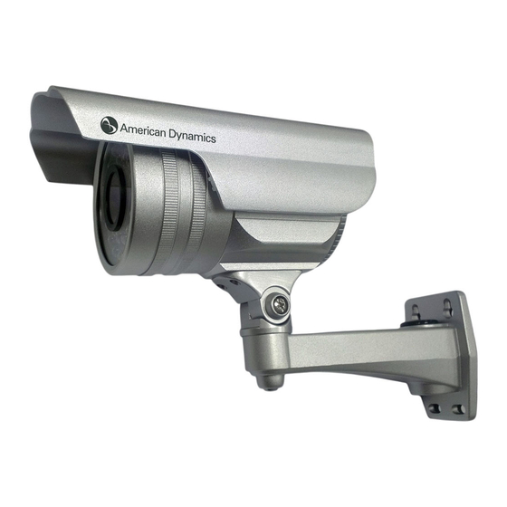
1 Parts Descriptions Overview IR illumination Light sensor (measures illumination light level) User’s Manual... -
Page 6: Precautions
Parts Descriptions Precautions Installation of this device shall be performed by qualified personnel in accordance with all local regulations and good installation practices. To prevent damage to your camera or injury to yourself or to others, read and comply with the safety precautions as follows: 1. -
Page 7: Installation
2 Installation Camera Installation Step 1 Screws can be loosened and the desired position can be adjusted. Loosen and tighten the screws by using a Torx driver. User’s Manual... - Page 8 Installation Step 2 To install the sunhood, please put the sunhood on the top of the camera, and then tighten the screw. To remove the sunhood, please first untighten the screw and then take the sunhood away from the camera. Discover 700 Series Outdoor IR Bullet Camera...
- Page 9 Installation Step 3 Use the template supplied on the quick installation guide to mark an appropriate mounting position on a wall, drilling to create apertures on the wall. Additionally, for proper routing of Video Output Terminal and Power Input Terminal cables, there may need to be a hole on the wall right at the center of the template.
-
Page 10: Connection And The Adjustment
Installation Connection and the Adjustment Camera Connection NEC Class 2 / Limited Power Source Supply Required Connect the Video Output Terminal to a video monitor or DVR. Connect the Power Input Terminal to the appropriate power supply. NOTE: This product requires the use of an NEC Class 2 or Limited Power Source (LPS) Supply. The power source must be stable and should only be installed by qualified personnel. -
Page 11: Camera Adjustment And Extra Connection
Installation Camera Adjustment and Extra Connection There is an adjustment mechanism on the back of the camera. Turn the cover on the back of the camera in the direction indicated below and remove the cover. User’s Manual... -
Page 12: Osd Menu Navigation
Installation Focus Adjuster: Adjusts the lens focus from near (N) to far (∞). Turning counterclockwise toward N would bias lens focus for near objects, whereas turning clockwise toward the ∞ setting would bias the focus for far-away objects. NOTE: Focus Adjuster must be used in conjunction with Field of View Adjuster. After adjusting of one of these two knobs (usually Field of View first), the other knob must also be adjusted to restore image focus. - Page 13 Installation Change item selection by shifting the cursor (OSD toggle switch) left or right. Sub-Menu (..) / Action (.) : In this OSD menu display, the item trailed by two dots .. has its associated sub-menu (e.g. VIEWING.. ), and the item trailed by just one dot . has its associated action (e.g.
- Page 14 Installation Move the cursor down or up to reach the option <VIEWING..>. Then click ENTER. MAIN MENU PRESETS WD_NORMAL EXPOSURE.. WHITE BALANCE 1 TOUCH* > VIEWING SETUP.. SYSTEM INFO.. SAVE/RESTORE.. EXIT MENU. We are now at the VIEWING sub-menu. Move the cursor down/up to PTZ and press ENTER. VIEWING VIEWING >...
-
Page 15: Osd Menu Descriptions
3 OSD Menu Descriptions OSD Menu Overview OSD Main Menu OSD Option / Sub-Menu OSD Menu Note In this OSD menu table, a submenu item may have an alternative name after entering that submenu. For example, for the menu item VIEWING, after choosing the PTZ.. -
Page 16: Presets
OSD Menu Descriptions PRESETS This menu item offers some pre-programmed camera settings ready for different scenarios. WD_NORMAL This setting is for normal surveillance circumstances with wide-dynamic-range enhancements. NORMAL This setting is for normal surveillance circumstances. INDOOR This setting is optimized for indoor surveillance. OUTDOOR This setting is optimized for outdoor surveillance. - Page 17 OSD Menu Descriptions areas in high-contrast scenarios. DAY EXPOSURE has these submenu items: WDR CTRL, WDR ZONE, EXPOSURE PREF, BLC, and DAY AGC. WDR CTRL: Specifies WDR (wide dynamic range) preset or user-adjustable control settings. Available choices are LOW, NORMAL, MEDIUM, HIGH, and CUSTOM .
-
Page 18: Night Exposure
OSD Menu Descriptions Border Contraction ZONE ZONE for adjustment The ZONE for adjustment becomes the rectangle with red double border lines. To move any border inward, simply shift the OSD toggle switch (or press any directional button) in the direction corresponding to that border. Then press ENTER to go back to the Position Adjustment stage. -
Page 19: White Balance
OSD Menu Descriptions WHITE BALANCE White balance is the mechanism of choosing and/or setting the “white color reference” of the current environment for optimal image color calibrations. The available white balance modes are: ATW Normal, 1 TOUCH*, MANUAL, and ATW Xtnd ATW Normal This option sets the camera to Auto-Tracking White-balance Normal mode, which automatically and continuously tracks video display contents (in the normal color temperature range of 2800~9100K) and... -
Page 20: Monitor
OSD Menu Descriptions MONITOR This option sets the camera to Auto-Tracking White-balance Normal mode, which automatically and continuously tracks video display contents (in the normal color temperature range of 2800~7500K) and adjusts the display for optimal white balance. This option (pan, tilt, zoom) allows the user to digitally zoom in to a particular region of the surveillance screen. - Page 21 OSD Menu Descriptions PRIVACY MASK – Enables (ON) or disables (OFF) the privacy mask option. If the privacy mask is enabled (ON), press ENTER to advance to the ENABLE MASKS submenu. ENABLE MASKS (1 to 6) Here the user can either enable (ON) or disable (OFF) any of Masks 1~6. For the other 6 masks (7~12), move the cursor to “NEXT.”...
-
Page 22: Setup
OSD Menu Descriptions ID POSITION – Specifies the desired position for ID display. The available options are: UP-LEFT / UP-CENTER / UP-RIGHT / DOWN-LEFT / DOWN-RIGHT SETUP The SETUP menu hosts miscellaneous adjustment parameters for camera operation. VIDEO STANDARD This option sets the standard for the output video. -
Page 23: Id Setup
OSD Menu Descriptions AI THRESH (-48 ~ 60): Adjusts the automatic iris control activation threshold boost (in dB; higher value means more threshold boost and therefore lower auto-iris control activation light level needed). Range of adjustment is -48 ~ 60 (dB). Lower the threshold boost if the iris control becomes unstable. -
Page 24: System Info
OSD Menu Descriptions NIGHT – The camera is set continuously to operate in night-time mode (continuous black-and-white surveillance video). PHOTO SENSOR – Day and Night operation modes are set to be controlled by the photo sensor (light sensor). NIGHT MODE: Sets up various parameters for night-time operations B/W+BURST –... -
Page 25: Specifications
4 Specifications General Specifications General Specifications TV System NTSC Image Sensor Pixim Seawolf D8800C 1/3" Sensor Effective Picture Element 758 (H) x 540 (V) 758 (H) x 540 (V) Scanning Frequency 60 Hz 50 Hz Resolution 690 HTVL-E Day Mode: 0.6 Lux (50 IRE, F=1.2, IR Off) Min. -
Page 26: Lens Specifications
Specifications Backlight Compensation (BLC) Full Range Day / Night Light sensor control D/N Digital Noise Reduction 3D Motion Adaptive (0~255) White Balance Control ATW Normal, AWB, Manual Standard Range 2800 K ~ 9100 K EX Range 2000 K ~ 11000 K Sync System INT/ LL Gamma Compensation...