American Dynamics ADCTDN0230P Instructions Manual
American dynamics instructions manual true d/n camera adctdn2412n, adctdn2412p, adctdn0230p
Hide thumbs
Also See for ADCTDN0230P:
- Specifications (25 pages) ,
- Information sheet (4 pages) ,
- Specifications (24 pages)
Table of Contents
Advertisement
ADCTDN2412N_P_EN.book Page 1 Friday, September 28, 2007 12:49 PM
TRUE D/N CAMERA
ADCTDN2412N
ADCTDN2412P
ADCTDN0230P
For Customer Use:
Enter below the Serial No. which is located on the
body. Retain this information for future reference.
Model No.
Serial No.
LST0617-001A
INSTRUCTIONS
8200-0852-00-A0
Advertisement
Table of Contents

Related Manuals for American Dynamics ADCTDN0230P


Summary of Contents for American Dynamics ADCTDN0230P
- Page 1 ADCTDN2412N_P_EN.book Page 1 Friday, September 28, 2007 12:49 PM TRUE D/N CAMERA ADCTDN2412N ADCTDN2412P ADCTDN0230P For Customer Use: Enter below the Serial No. which is located on the body. Retain this information for future reference. Model No. Serial No. LST0617-001A...
- Page 2 ADCTDN2412N_P_EN.book Page 2 Friday, September 28, 2007 12:49 PM FOR USA These are general IMPORTANT SAFEGUARDS and certain items may not apply to all appliances. IMPORTANT SAFEGUARDS Read all of these instructions. Save these instructions for later use. All warnings on the product and in the operating instructions should be adhered to.
- Page 3 ADCTDN2412N_P_EN.book Page 3 Friday, September 28, 2007 12:49 PM Do not allow anything to rest on the power cord. Do not locate this appliance where the cord will be abused by persons walking on it. Follow all warnings and instructions marked on the appliance. Do not overload wall outlets and extension cords as this can result in fire or electric shock.
-
Page 4: Introduction
ADCTDN2412N_P_EN.book Page 4 Friday, September 28, 2007 12:49 PM Introduction Safety Precautions FOR USA AND CANADA CAUTION RISK OF ELECTRIC SHOCK DO NOT OPEN CAUTION : TO REDUCE THE RISK OF ELECTRIC SHOCK. DO NOT REMOVE COVER (OR BACK). NO USER-SERVICEABLE PARTS INSIDE.REFER SERVICING TO QUALIFIED SERVICE PERSONNEL. - Page 5 ADCTDN2412N_P_EN.book Page 5 Friday, September 28, 2007 12:49 PM INFORMATION FOR USA INFORMATION This equipment has been tested and found to comply with the limits for a Class B digital device, pursuant to Part 15 of the FCC Rules. These limits are designed to provide reasonable protection against harmful interference in a residential installation.
- Page 6 ADCTDN2412N_P_EN.book Page 6 Friday, September 28, 2007 12:49 PM Introduction Safety Precautions (continued) Information for Users on Disposal of Old Equipment [European Union] This symbol indicates that the electrical and electronic equipment should not be disposed as general household waste at its end-of- life.
- Page 7 ADCTDN2412N_P_EN.book Page 7 Friday, September 28, 2007 12:49 PM POWER SYSTEM ADCTDN0230P this unit operates on a mains supply voltage of 220V to 240V AC, 50/60HZ. ADCTDN2412N/P these units are to be powered by DC 12V or an AC 24V power supply.
-
Page 8: Features
: Indicates reference data regarding limitations on functions, usage and the like. : Indicates a reference page or item. ● American Dynamics holds the copyright to this manual. Any part or all of this manual may not be reproduced without prior consent from the company. -
Page 9: Table Of Contents
ADCTDN2412N_P_EN.book Page 9 Friday, September 28, 2007 12:49 PM Contents Introduction Safety Precautions ... 4 Features ... 8 Contents ... 9 Operating Precautions ... 10 Name of Parts and their Functions ... 12 Setup Flow for Connection/Settings ... 17 Mounting the lens ... 18 Connecting the back panel ... -
Page 10: Operating Precautions
ADCTDN2412N_P_EN.book Page 10 Friday, September 28, 2007 12:49 PM Introduction Operating Precautions Storage and Location of Use This camera has been designed for indoor use. When you use it outdoors, be sure to use a housing or the like. Do not install or use the camera in the following places. ●... - Page 11 ADCTDN2412N_P_EN.book Page 11 Friday, September 28, 2007 12:49 PM Others This camera comes with a built-in AGC circuit. The sensitivity increases automatically at a dark place and the screen may appear grainy. This is not a malfunction. While the AGC is activated, if a transceiver which causes strong electromagnetic wave is used near the camera, the picture may suffer from beat.
-
Page 12: Name Of Parts And Their Functions
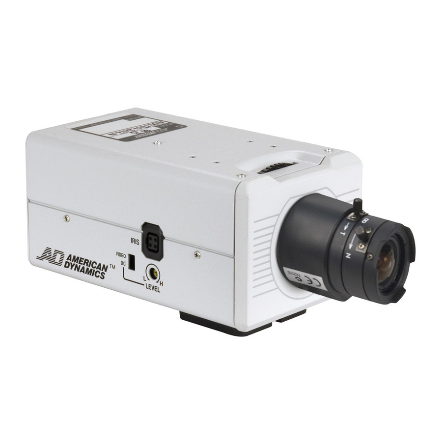
ADCTDN2412N_P_EN.book Page 12 Friday, September 28, 2007 12:49 PM Introduction Name of Parts and their Functions Front/Bottom/Side panel IRIS VIDEO LEVEL Back focus adjustment ring This ring switches between back focus adjustment and lens mounting method. When adjustment is required, loosen the back focus locking screw J by turning it anti-clockwise. - Page 13 ADCTDN2412N_P_EN.book Page 13 Friday, September 28, 2007 12:49 PM [IRIS] Iris Terminal This is connected to an autoiris control lens. [VIDEO,DC] Iris Selector Switch This should be set according to the type of lens if an autoiris control lens is used.
- Page 14 ADCTDN2412N_P_EN.book Page 14 Friday, September 28, 2007 12:49 PM Introduction Name of Parts and their Functions (continued) Back panel ADCTDN2412 CLASS 2 ONLY SEE INSTRUCTION ISOLATED POWER ONLY MANUAL POWER DC12V d AC24V H MENU VIDEO OUT SELECTOR ADCTDN0230P SEE INSTRUCTION MANUAL POWER MENU VIDEO OUT SELECTOR...
- Page 15 ADCTDN2412N_P_EN.book Page 15 Friday, September 28, 2007 12:49 PM [AC24V,DC12V] Power input terminal To connect to AC 24 V or DC 12 V power supply. (A Pg. 21) [AUX,GND] External terminals This terminal is for the input/output signals that are set in the AUX MODE of the AUX FUNCTION screen.
- Page 16 ADCTDN2412N_P_EN.book Page 16 Friday, September 28, 2007 12:49 PM Introduction Name of Parts and their Functions (continued) [POWER] Power indicator lamp This lamp lights up when power is supplied to the camera. Mounting Screw for Fall Prevention Wire Use this screw when mounting the fall prevention wire to this unit. (Fall prevention wire is not supplied with this product.) Note: ●...
-
Page 17: Setup
ADCTDN2412N_P_EN.book Page 17 Friday, September 28, 2007 12:49 PM Setup Flow for Connection/Settings Follow the procedures below to connect/set this unit. Turn off the power of devices to be used before connecting the cables. Mounting the lens (A Pg. 18) step 1 Mount the lens. -
Page 18: Mounting The Lens
ADCTDN2412N_P_EN.book Page 18 Friday, September 28, 2007 12:49 PM Setup Mounting the lens VIDEO IRIS VIDEO LEVEL 4 pin plug... - Page 19 ADCTDN2412N_P_EN.book Page 19 Friday, September 28, 2007 12:49 PM Check the mounting method of the lens before mounting ● This camera is set to CS-mount lens before shipment. To use a C-mount lens, loosen the back focus locking screw with a screwdriver, turn the back focus adjustment ring with your finger or the screwdriver and change the mounting method.
-
Page 20: Connecting The Back Panel
Setup Connecting the back panel Connect to AC 24 V or Connect to AC 220 DC 12 V power supply V-240 V power supply (ADCTDN2412N/P) (ADCTDN0230P) CLASS 2 ONLY SEE INSTRUCTION ISOLATED POWER ONLY MANUAL POWER DC12V d AC24V H... - Page 21 If the wrong cable is connected, the internal circuit may be damaged. Do not use the camera. Bring it to your nearest American Dynamics dealer for inspection. ADCTDN0230P (AC 220 V-240 V) Connect the power supply cable to the AC 220 V-240 V power supply. Note: ●...
- Page 22 ADCTDN2412N_P_EN.book Page 22 Friday, September 28, 2007 12:49 PM Setup Connecting the back panel (continued) Connecting alarm input/output terminal Alarm input terminal Connect infrared sensor, door sensor, metal sensor or sensor of manual switch and the like. ● To prevent noise from entering the internal circuit, supply non-voltage setting signal.
-
Page 23: Mounting The Camera
ADCTDN2412N_P_EN.book Page 23 Friday, September 28, 2007 12:49 PM Mounting the camera When mounting the camera on a mount, pan/tilt and the like, use the camera- mounting screw hole located on the camera-mounting bracket. Camera-mounting Camera-mounting bracket fixing screw hole screws (x2: M2.6 x 6 mm) Camera-mounting bracket Rotation-preventive hole... - Page 24 ADCTDN2412N_P_EN.book Page 24 Friday, September 28, 2007 12:49 PM Setup Mounting the camera (continued) Mounting the camera-mounting bracket on top of the camera The camera-mounting bracket is originally mounted at the bottom of the camera before shipment but it can also be mounted on top of the camera. ●...
- Page 25 ADCTDN2412N_P_EN.book Page 25 Friday, September 28, 2007 12:49 PM Remove the camera-mounting bracket locking screws (x2). The camera-mounting bracket is removed from the camera. Mounting the camera-mounting bracket on top of the camera Mounting the camera onto a mount, pan/tilt unit and the like Note: ●...
-
Page 26: Adjusting The Back Focus
ADCTDN2412N_P_EN.book Page 26 Friday, September 28, 2007 12:49 PM Setup Adjusting the back focus This camera is adjusted to a optimum wide range for CS-mount lens before shipment but readjustment is required when using zoom lens or C-mount lens or when the lens focus ring is out of focus. Use the following methods to adjust the back focus. - Page 27 ADCTDN2412N_P_EN.book Page 27 Friday, September 28, 2007 12:49 PM With a fixed-focus lens If the focus cannot be adjusted correctly with the lens focus ring, adjust the back focus as follows. Loosen the back focus locking screw by turning it anti-clockwise with a + screwdriver.
-
Page 28: Adjusting The Lens
ADCTDN2412N_P_EN.book Page 28 Friday, September 28, 2007 12:49 PM Setup Adjusting the lens After the connection is complete, turn on the camera, display an image on the monitor and check the video image. In the case of an autoiris control lens, the camera has been factory-adjusted to the best position, but it may need to be adjusted according to the condition of the object or the lens combination. - Page 29 ADCTDN2412N_P_EN.book Page 29 Friday, September 28, 2007 12:49 PM LEVEL adjustment Monitor screen LEVEL adjustment direction To darken Anti-clockwise (Towards L) To brighten Clockwise (Towards H) Memo: ● If the LEVEL sensitivity adjustment is turned excessively to L, the sensitivity increases because of the AGC function of the camera and the image looks grainy.
-
Page 30: Adjusting The Awc (One Touch Manual Balance)
ADCTDN2412N_P_EN.book Page 30 Friday, September 28, 2007 12:49 PM Setup Adjusting the AWC (one touch manual balance) Each light source has its own color temperature. Therefore, when the main light source lighting an object is changed, press the SET button for a while and adjust the AWC again. - Page 31 ADCTDN2412N_P_EN.book Page 31 Friday, September 28, 2007 12:49 PM Place a white object at the center of the screen, under the same lighting condition as the object to be shot and zoom in to fill the screen with white. Press the SET button for approx. one second. AWC adjustment begins.
-
Page 32: Setting
ADCTDN2412N_P_EN.book Page 32 Friday, September 28, 2007 12:49 PM Setting Menu basic operation CLASS 2 ONLY SEE INSTRUCTION ISOLATED POWER ONLY MANUAL POWER DC12V d MENU button AC24V H MENU VIDEO OUT SELECTOR SET button and SELECTOR switch Press the MENU button The MENU screen is displayed. - Page 33 ADCTDN2412N_P_EN.book Page 33 Friday, September 28, 2007 12:49 PM Press the SELECTOR switch up and down (J, K) to set the cursor (E) to a desired item. TITLE/VIDEO CAMERA TITLE EDIT.. W. BALANCE SHUTTER.. GAIN.. B&W/COLOR.. BLC MODE <MENU>RETURN Press the SELECTOR switch left or right (H, I) to change the setting. When a setting has been changed, a change mark (Z) is displayed.
-
Page 34: The Flow Of Menu Screen
ADCTDN2412N_P_EN.book Page 34 Friday, September 28, 2007 12:49 PM Setting The flow of menu screen... - Page 35 ADCTDN2412N_P_EN.book Page 35 Friday, September 28, 2007 12:49 PM...
-
Page 36: Aux Function Screen
ADCTDN2412N_P_EN.book Page 36 Friday, September 28, 2007 12:49 PM Setting AUX FUNCTION screen Item Functions and settings AUX MODE This item sets the signal input or output of the AUX terminal. B&W OUT : A signal is output when the camera switches to B&W or Color mode. -
Page 37: Title/Video Screen
ADCTDN2412N_P_EN.book Page 37 Friday, September 28, 2007 12:49 PM Item Functions and settings INPUT This sets the polarity of the AUX input signal. POLARITY MAKE : When the contact between all alarm input terminals and GND terminals changes from open to close, the alarm will activate. BREAK : When the contact between all alarm input terminals and GND terminals changes from... - Page 38 ADCTDN2412N_P_EN.book Page 38 Friday, September 28, 2007 12:49 PM Setting TITLE/VIDEO screen (continued) Item Functions and settings W.BALANCE (continued) AWC SET: (one touch) (Manual The Auto White Control (automatic white balance adjustment) mode adjusts the white balance automatically and sets it not to react to any further scene lighting changes.
- Page 39 ADCTDN2412N [Setting: NORMAL, 1/100, 1/250, 1/500, 1/1000, 1/2000, 1/4000, 1/10000] [Default setting: NORMAL] ADCTDN2412P/ADCTDN0230P [Setting: NORMAL, 1/120, 1/250, 1/500, 1/1000, 1/2000, 1/4000, 1/10000] [Default setting: NORMAL] Memo: ● When SHUTTER item is set to AAUTOB, A- - -B will be displayed and settings is disabled.
- Page 40 ADCTDN2412N_P_EN.book Page 40 Friday, September 28, 2007 12:49 PM Setting TITLE/VIDEO screen (continued) Item Functions and settings GAIN This item sets the gain. Memo: ● If the gain is increased, the screen appears grainy in a dark place. MODE Select the gain adjustment mode. Sensitivity increases electronically for an object with low illumination.
- Page 41 ADCTDN2412N_P_EN.book Page 41 Friday, September 28, 2007 12:49 PM Item Functions and settings GAIN (continued) This item sets a maximum gain of the AGC (Automatic GAIN Gain Control). 0(OFF) : No AGC function. HIGH : Increase the gain up to a maximum of 26dB according to the illumination of an object.
- Page 42 ADCTDN2412N_P_EN.book Page 42 Friday, September 28, 2007 12:49 PM Setting TITLE/VIDEO screen (continued) The word ACOLORB display differs depending on the model. ACOLORB is displayed for ADCTDN2412N and ACOLOURB is displayed for ADCTDN2412P/ADCTDN0230P. From this point onwards, ACOLORB will be used for indication. Item Functions and settings B&W/COLOR This item sets the mode switching of B&W and Color.
- Page 43 MODE [Default setting: AUTO] (continued) ZDisplay for ADCTDN2412N. For ADCTDN2412P/ ADCTDN0230P, COLOUR is displayed. Memo: To ensure a successful B&W/Color switching ● If the MODE item of B&W/COLOR is set to AAUTOB, the B&W/Color setting can be switched according to the brightness of the object, but the condition of illumination and field angle may make this difficult.
- Page 44 : Switches to B&W mode when the signal level of the object indicates high illumination. [Default setting: LOW] ZDisplay for ADCTDN2412N. For ADCTDN2412P/ ADCTDN0230P, COLOUR is displayed. Memo: ● When MODE item of B&W/COLOR is set to AAUTOB, A- - -B will be displayed and settings is disabled.
-
Page 45: Display Screen
ADCTDN2412N_P_EN.book Page 45 Friday, September 28, 2007 12:49 PM Item Functions and settings BLC MODE Sets the backlight compensation function. Set this item when there is a bright light source in the background of the object and the object becomes dark. Set such that unnecessary light source is outside the photometry area. -
Page 46: Ll Adjustment Screen
This item can only operate in a region with a power frequency of 60 Hz. [Setting: -131 to 0 to 131] [Default setting: 0] ADCTDN2412P/ADCTDN0230P This item can only operate in a region with a power frequency of 50 Hz. [Setting: -156 to 0 to 156]... -
Page 47: Factory Setting Screen
ADCTDN2412N_P_EN.book Page 47 Friday, September 28, 2007 12:49 PM FACTORY SETTING screen The values set on the menu are returned to the default settings. Item Functions and settings CANCEL Does not return to the default setting. The screen returns to the main menu. CLEAR(WITH Returns settings except titles to the default setting. -
Page 48: Detailed Setting
The first character from the character area flashes on and off and is ready for input. TITLE/VIDEO CAMERA TITLE EDIT.. W. BALANCE SHUTTER.. GAIN.. B&W/COLOR.. BLC MODE <MENU>RETURN <SET>SUB MENU TITLE/VIDEO screen Character area Space Flashing Only displayed in ADCTDN2412P/ ADCTDN0230P CAMERA TITLE EDIT screen Input frame Title input area... - Page 49 ADCTDN2412N_P_EN.book Page 49 Friday, September 28, 2007 12:49 PM Press the SELECTOR switch up, down, left or right (J, K, H, I) and select a character from the character area. The selected character is displayed flashing on and off. Press the SET button The first character is confirmed and the blinking title input area moves to the second character.
-
Page 50: Manual Adjustment Of White Balance
ADCTDN2412N_P_EN.book Page 50 Friday, September 28, 2007 12:49 PM Detailed setting Manual adjustment of white balance When automatic adjustment of the white balance results in a “reddish screen”, adjust the white balance manually. CLASS 2 ONLY SEE INSTRUCTION ISOLATED POWER ONLY MANUAL POWER MENU button... - Page 51 ADCTDN2412N_P_EN.book Page 51 Friday, September 28, 2007 12:49 PM Press the SELECTOR switch up or down (J, K) and select the hue to be adjusted (R GAIN or B GAIN). Press the SELECTOR switch left or right (H, I) to change the setting. R GAIN : Adjusts the R (red) hue during AWC.
-
Page 52: Output Of B&W/Color Switching Signal
ADCTDN2412N_P_EN.book Page 52 Friday, September 28, 2007 12:49 PM Detailed setting Output of B&W/Color switching signal It is possible to output B&W/Color switching signal from the AUX terminal on the back of this camera. B&W/Color switching signal is output by setting both the AUX MODE and B&W/COLOR items. - Page 53 ADCTDN2412N_P_EN.book Page 53 Friday, September 28, 2007 12:49 PM Set the B&W/COLOR item to AUTO Select the item B&W/COLOR on the TITLE/VIDEO screen and press the SET button. The B&W/COLOR screen is displayed. Press the SELECTOR switch up or down (J, K) and select MODE. Press the SELECTOR switch left or right (H, I) and set to AUTO.
-
Page 54: Control By B&W/Color Switching Signal From External
Control by B&W/Color switching signal from external You can use the switching signal from an external control device to link the B&W/Color switching or near-infrared illumination of this camera. Consult your nearby American Dynamics dealer on the connecting devices. Example) AUX MODE... - Page 55 ADCTDN2412N_P_EN.book Page 55 Friday, September 28, 2007 12:49 PM When performing only B&W/Color mode switching without changing other video settings Select the item AUX MODE on the AUX FUNCTION screen. Press the SELECTOR switch left or right (H, I) and set to AIR INB. AUX FUNCTION AUX MODE IR IN...
-
Page 56: Others
ADCTDN2412N_P_EN.book Page 56 Friday, September 28, 2007 12:49 PM Others Specifications Camera Video standard ADCTDN2412N : NTSC ADCTDN2412P/ADCTDN0230P : PAL Image pickup device : 1/3 type IT CCD Scanning frequency ADCTDN2412N : 15.734 kHz (horizontal), 59.94 Hz (vertical) ADCTDN2412P/ADCTDN0230P : 15.625 kHz (horizontal), 50 Hz (vertical) - Page 57 General Power supply ADCTDN2412N : AC 24V 60 Hz (+33% -15%), DC 12V (±15%) : AC 24V 60 Hz (+33% -15%), DC 12V (±15%) ADCTDN2412P ADCTDN0230P : AC187V-276V 50Hz/60 Hz Power consumption ADCTDN2412N : 4.8 W ADCTDN2412P : 400 mA...
- Page 58 ADCTDN2412N_P_EN.book Page 58 Friday, September 28, 2007 12:49 PM Others Specifications (continued) Dimensions [Unit: mm] ADCTDN2412N U1-32 1/4-20UNC...
- Page 59 ADCTDN2412N_P_EN.book Page 59 Friday, September 28, 2007 12:49 PM ADCTDN0230P U1-32 1/4-20UNC T Specifications and appearance of this camera and related products are subject to change for improvements without notice.
- Page 60 ADCTDN2412N_P_EN.book Page 60 Friday, September 28, 2007 12:49 PM LST0617-001A 8200-0852-00-A0...