
Related Manuals for Raymarine RA1072HD


Summary of Contents for Raymarine RA1072HD
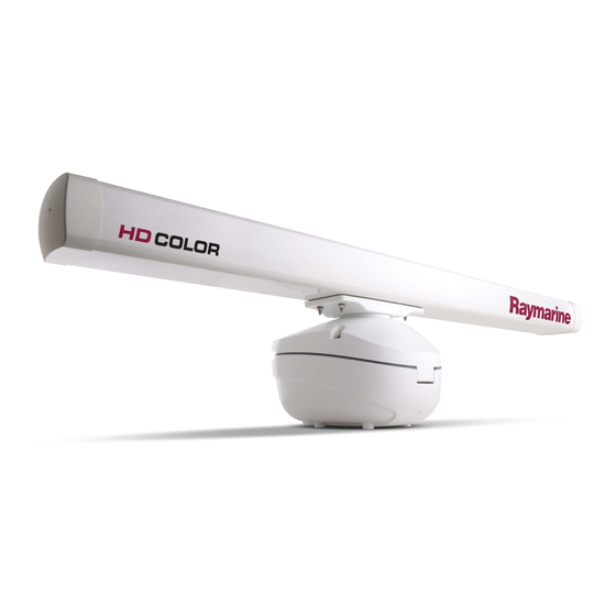
- Page 1 Digital Radar Scanners Installation Manual Document number: 87087-1 Date: June 2007...
-
Page 3: Table Of Contents
C o n t e n t s Contents Important Information..................1 Intended use................... 1 Raymarine Support ................ 3 Chapter 1: System Overview ..............7 1.1 Introduction ................7 System configuration..............8 1.2 EMC installation guidelines ............9 Connections to other equipment........... 10 1.3 Unpacking and inspecting the components ...... - Page 4 2.5 Fitting the open array to the pedestal ........31 2.6 System Connections ..............33 Connecting the digital radar cable..........33 Digital Radar Connections ............34 Data Connections ................. 34 Power Connections ..............34 Chapter 3: Maintenance and Troubleshooting ........37 3.1 EMC Conformance ..............
-
Page 5: Important Information
RECOMMEND that an Authorized Raymarine Service Representative fits this product. You will only receive full warranty benefits if you can show that an Authorized Raymarine Service Representative has installed or commissioned this product. This radar equipment must be installed, commissioned and operated in accordance with the Raymarine instructions provided. - Page 6 Distance to 100 W/m point Distance to 10 W/m point RA1048HD Worst case (4 kW) 1.0 M RA1072HD Worst case (4kW) 1.0 M RA2048SHD (12 kW) RA3072SHD (12 kW) When properly installed and operated, the use of this radar will con- form to the requirements of •...
-
Page 7: Raymarine Support
Raymarine Support Raymarine products are supported by a network of Authorized Service Representatives. For information on Raymarine products and services, contact either of the following: United States Raymarine Inc. 21 Manchester Street Merrimack NH 03054-4801, USA Telephone +1 603 881 5200 +1 603 864 4756 www.raymarine.com... - Page 8 It also provides information on maintenance and trouble-shooting. Warranty To register your new Raymarine product, please fill out the warranty card included in the box or go to: www.raymarine.com It is important that you complete the owner information and return the card to receive full warranty benefits, including notification of software updates if they are required.
- Page 9 Although the WEEE Directive does not apply to all Raymarine products, we support its policy and ask you to be aware of the correct method for disposing of such products.
-
Page 10: General Information
FCC or IC rules, and void the user's authority to operate the equipment. Declaration of Conformity Raymarine UK Ltd. hereby declares that the 4kW & 12kW Digital Radars are in compliance with the essential requirements and other relevant provisions of the R&TTE Directive 1995/5/EC. -
Page 11: Chapter 1: System Overview
Chapter 1: System Overview 1.1 Introduction This handbook provides instructions to assist you in the installation of the following digital radars: 4 kW High definition open array 4kW Super high definition open digital radar array digital radar 48” Array scanner 48”... -
Page 12: System Configuration
System configuration Examples of digital radar systems as illustrated below. For more detailed systems please see your individual display Owner’s Handbook. Radar GPM400 SeaTalk switch Display VCM100 Power D10430-1... -
Page 13: Emc Installation Guidelines
For optimum EMC performance, we recommend that: • Raymarine equipment and the cables connected to it are: • At least 3 ft (1 m) from any equipment transmitting or cables carrying radio signals e.g. VHF radios, cables and antennas. -
Page 14: Connections To Other Equipment
Raymarine equipment. Connections to other equipment If Raymarine equipment is to be connected to other equipment using a cable not supplied by Raymarine, a suppression ferrite MUST always be fitted to the cable close to the Raymarine unit. -
Page 15: Unpacking And Inspecting The Components
1.3 Unpacking and inspecting the components Unpack your system carefully, to prevent damage to the equipment. Check that you have all the correct system components. What‘s in the box? Parts supplied Pedestal Plain Spring washer washer (x8) Lifting (x4) (x4) (x3) Template Stud... -
Page 16: Selecting The Digital Radar Unit Site
1.4 Selecting the digital radar unit site Digital radar dimensions Maximum rotation 48"- 1330 mm (52.4 in), 72"- 1950 mm (76.8 in) Centre of rotation Centre of rotation 111 mm 150 mm 151 mm 92 mm 140 mm 92 mm (4.4 in) (5.9 in) (5.95 in) - Page 17 • Height: The digital radar unit should normally be mounted as high as practical above the waterline, for three reasons: • For safety reasons the digital radar should be out of range of personnel, preferably above head height. This avoids mechanical danger and electromagnetic contact, particularly with the eyes.
- Page 18 a much greater range. For this reason the angular width and rela- tive bearing of any shadow sector must be determined at installa- tion. Sometimes shadowing can be seen by increasing the radar gain until noise is present. Dark sectors indicate possible shad- owed areas.
-
Page 19: Mounting Surfaces
1.5 Mounting Surfaces The digital radar unit can be installed on a mast platform, an arch, or a bridge structure. Make sure that the platform surface is flat and the units drain hole is not obstructed. If there is any doubt concerning the appropriate type of hardware, consult your boat dealer or representative for their recommendations. -
Page 20: Setting The Radiation Plane
1.6 Setting the radiation plane The digital radar unit should be mounted so that the array rotates parallel to the waterline. The radar beam is approximately 25° wide in the vertical direction, providing good target detection during the vessel’s pitching and rolling. Ideal Radiation Plane 12.5°... -
Page 21: Cable Requirements
The shims may be made from aluminium plate wedges, simple flat washers, or an angled wooden block. For thick shims, you may need longer securing bolts than the M10 studding supplied, ( see note in Installing the Digital Radar Components on p.26 ). 1.7 Cable requirements This section provides details on selecting the appropriate cables for your system. - Page 22 These cable lengths should be sufficient to complete the cable run required on most vessels, part numbers for cables are shown in the table below. Table 1-1: Item Part No. Option for: 4 kW digital radar Pedestal E52069 High definition 4 kW digital radar Pedestal E52081 Super high definition...
- Page 23 You should NOT cut and re-join any of the supplied cables. If it is necessary to extend the SeaTalk data cable you should use a Raymarine supplied extension cable ( see Table 1-1:, p.18 ). For the SeaTalk data cable extensions you must: •...
-
Page 24: Power Requirements
12 V and 24 V systems Extensions to the supplied power cable should be kept to the minimum length possible. Raymarine recommends that the power should be fed directly from the output of the battery isolator switch or DC distribution panel via its own dedicated cable system to the VCM100. -
Page 25: Voltage Converter Module (Vcm100)
battery isolator switch/DC distribution panel to the VCM100. Do not exceed these lengths as unreliable operation may result. Table 1-2: *Max total distance from power supply to Voltage Converter Module (VCM100) AWG (American Wire Gauge) Maximum distance (12 V 6.0 M 8.0 M 10.0 M 15.0 M... - Page 26 Power out The ‘POWER OUT’ port is used to connect the digital radar power cable to supply the 42 V required, also ensure that the screen port is used. The VCM100 has status LED’s fitted ( see Table 3-2:, p.43 for trouble-shooting advice ).
-
Page 27: Grounding The Digital Radar System
1.9 Grounding the digital radar system It is important that an effective RF ground is connected to the radar system. You must ground the radar by connecting the drain/screen wire (green) of the power cable to the ground point (screen) of the VCM100, the ship’s RF ground system should be connected to the other screen point on the VCM100 when running the power cables. -
Page 28: Circuit Breaker And Fuse Ratings
1.10Circuit breaker and fuse ratings It is recommended that power is fed directly to the VCM100 via its own dedicated cable system and MUST be protected by a thermal circuit breaker or fuse, fitted close to the power connection, then run power from the output of the VCM100 to the digital radar, ( the connection from the output of the VCM100 to the digital radar does not need any fuse or circuit breakers connecting ). -
Page 29: Chapter 2: Installing The Digital Radar Components
Installation of the digital radar should only be undertaken by a competent installer. If you have any difficulty with the installation, please contact your local Raymarine dealer or distributor. The digital radar system is supplied in three sections; the pedestal unit, the antenna and the Voltage Converter Module (VCM100). -
Page 30: Installing The Vcm 100
digital radar in place before fixing the antenna. You should never lift the unit by the attached open array antenna. Please read and understand chapter 1 before you start to install any of the components of the digital radar system. 2.2 Installing the VCM 100 CAUTION: It is important to keep the cable run from the DC distribution... -
Page 31: Securing The Pedestal To The Mounting Platform
2.3 Securing the pedestal to the mounting platform 1. Using the paper template supplied with the mounting kit, mark the flat mounting surface in-line with the holes, and drill as indicated on the template. Preparing mounting holes Mounting platform IMPORTANT Ensure mounting platform is adequately robust for 1. - Page 32 3. Grease the studs with Denso paste (supplied) then in turn, hand tighten the 4 studs into the pedestal. Preparing mounting studs Hand tighten stud into Apply Denso Paste pedestal. to stud. D10492-1 Note: If the studding supplied is not long enough for the mounting surface thickness, use M10 stainless steel, grade A4-70 studding of a suitable length.
- Page 33 CAUTION: DO NOT lift the unit with the open array antennae attached. 4. Using suitable lifting equipment (see warning on page -25 ), raise the pedestal over the mounting surface. Carefully lower into position, taking care that the studs pass through the holes without damaging the threads.
- Page 34 W A R N I N G : Support the pedestal unit until it has been secured to the mounting platform. It is important that all four sets of nuts and washers are used to secure the pedestal to the mounting platform.
-
Page 35: Removing The Lifting Eyes
2.4 Removing the lifting eyes Note: Complete this step on each bolt, one by one. 1. Loosen the first self retaining bolt securing the lifting eye to the pedestal lid, do this enough to remove the lifting eye. 2. Once the lifting eye is removed, re-tighten the bolt to 5.2 lb ft. (7 NM) torque. - Page 36 Note: Retain the protective cap, for use if the open array is removed from the pedestal in the future. If the pin is damaged during the following operation you should contact your service dealer. 3. Move the antenna mounting bracket so it sits on the East to West axis of the digital radar.
-
Page 37: System Connections
2.6 System Connections CAUTION: The digital radar connector on one end of the cable is a moulded plug that should not be removed. DO NOT remove this moulded plug. Connecting the digital radar cable Line up the two arrows (one on the radar cable, one on the radar connector, on the base). -
Page 38: Digital Radar Connections
Digital Radar Connections The digital radar cable consists of 2 parts, power and data. The moulded connector plugs in to the digital radar. The cable’s power cores are routed to the VCM100. The RJ45 data connector goes to the SeaTalk connection as described in Installing the Digital Radar Components on p.34 . - Page 39 However, if the scanner is being serviced, or if anyone needs to work in the vicinity of the open array, the switch should be set to OFF. The following cable connections to the VCM100 are required. Table 2-1: VCM100 Out +ve Black VCM100 Out -ve Green...
-
Page 41: Chapter 3: Maintenance And Troubleshooting
• All connections have been made • All connecting wires are secured and protected as necessary Note: We recommend that an certified and authorized Raymarine agent checks the installation before going to sea . -
Page 42: Set Up, Alignment And Timing Checks
3.3 Set up, alignment and timing checks Switch on and initial set up On the digital radar, ensure the power switch is set to ON. Switch on the display unit. The magnetron warm-up sequence should start, after which the unit should enter Standby mode. If necessary, adjust the lighting and contrast. -
Page 43: Open Array Position Alignment
Parking alignment When the radar is in standby or powered down, the antenna should park (rest) facing forward, (so you can see the Raymarine logo when looking towards the scanner from the front of the boat). A parking offset angle determines where the scanner parks, and you can set this, so the scanner parks correctly. -
Page 44: Maintenance
Switch off the display unit before removing the power cord. Suppression ferrites Raymarine cables may be fitted with suppression ferrites. These are important for correct EMC performance. Any ferrite removed for maintenance purposes must be replaced in the original position once the maintenance is complete. -
Page 45: Servicing And Safety
Raymarine equipment should only be serviced only by authorized Raymarine service technicians. They will ensure that service pro- cedures and replacement parts used will not affect performance. There are no user serviceable parts in any Raymarine product. • Some products generate high voltages, so never handle the cables/connectors when power is being supplied to the equip- ment. -
Page 46: Problem Solving
3.5 Problem Solving All Raymarine products are subjected to comprehensive test and quality assurance programmes prior to packing and shipping. However, if this radar unit or VCM100 should develop a fault, please refer to the following table’s to identify the most likely cause and the corrective action required to restore normal operation. -
Page 47: Vcm100 Status Led Sequence's
Chapter 3: Maintenance and Troubleshooting VCM100 status LED sequence’s Table 3-2: LED name Operating color Working condition Green (solid) Radar operating normally Fault Red (solid) Fault condition Sleep Yellow (flashing) (Radar in Standby) Yellow (solid) Fault condition, self recovers after 20 seconds...