
Related Manuals for Raymarine CYCLONE


Summary of Contents for Raymarine CYCLONE
- Page 1 CYCLONE & CYCLONE PRO Installation instructions English (en-US) Date: 05-2021 Document number: 87402-1 © 2021 Raymarine UK Limited...
- Page 3 Please check the website to ensure you have the latest documentation. Publication copyright Copyright ©2021 Raymarine UK Ltd. All rights reserved. No parts of this material may be copied, translated, or transmitted (in any medium) without the prior written permission of Raymarine UK Ltd.
-
Page 5: Table Of Contents
Suppression ferrites ......................... 12 Connections to other equipment.................... 12 Compass safe distance ......................12 Declaration of Conformity (Cyclone) ..................13 Declaration of Conformity (Cyclone Pro) ................13 Declaration of Conformity (VCM100) ..................13 Radar licensing.......................... 13 FCC Notice - Radar ........................13 FCC Approval codes ........................ - Page 6 4.1 Parts supplied (pedestal) ....................26 4.2 Parts supplied (antenna)....................27 4.3 Parts supplied (VCM100) ....................27 Chapter 5 Product dimensions..................29 5.1 Cyclone series ........................30 5.2 VCM100 Voltage Convertor Module................30 Chapter 6 Location requirements .................. 31 6.1 Potential ignition source....................32 6.2 Radar position overview....................
- Page 7 13.4 Radar target acquisition data source requirements ............ 75 13.5 Doppler data source requirements ................75 13.6 VCM100 LED indications....................76 Chapter 14 Technical support..................77 14.1 Raymarine product support and servicing..............78 Chapter 15 Technical specification ................81 15.1 Technical specification..................... 82 Chapter 16 Spares and accessories................85 16.1 Accessories ........................
-
Page 9: Chapter 1 Important Information
Certified Installation Raymarine recommends certified installation by a Raymarine approved installer. A certified installation qualifies for enhanced product warranty benefits. Contact your Raymarine dealer for further details, and refer to the separate warranty document packed with your product. Warning: Product installation and operation •... - Page 10 Caution: Service and maintenance This product contains no user serviceable components. Please refer all maintenance and repair to authorized Raymarine dealers. Unauthorized repair may affect your warranty. Caution: Doppler “wagon-wheeling” effect • There are limits to the maximum relative speed that the radar scanner can measure when processing Doppler targets.
-
Page 11: Transmitted Power Density Levels
Raymarine. Raymarine is not responsible for damages or injuries caused by your use or inability to use the product, by the interaction of the product with products manufactured by others, or by errors in information utilized by the product supplied by third parties. -
Page 12: Emc Installation Guidelines
Connections to other equipment Requirement for ferrites on non-Raymarine cables If your Raymarine equipment is to be connected to other equipment using a cable not supplied by Raymarine, a suppression ferrite MUST always be attached to the cable near the Raymarine unit. -
Page 13: Declaration Of Conformity (Cyclone)
Declaration of Conformity (Cyclone) FLIR Belgium BVBA declares that the radio equipment type Cyclone Open Array radars, part number E70620 when fitted with antennas, E70628, E70629 or E70630, are in compliance with the Radio Equipment Directive 2014/53/EU. The original Declaration of Conformity certificate may be viewed on the relevant product page at www.raymarine.com/manuals. -
Page 14: Warranty Registration
In addition, our policy of continuous product improvement may change specifications without notice. As a result, Raymarine cannot accept liability for any differences between the product and this document. Please check the Raymarine website (www.raymarine.com) to ensure you have the most up-to-date version(s) of the documentation for your product. -
Page 15: Chapter 2 Document Information
Chapter 2: Document information Chapter contents • 2.1 Document information on page 16 Document information... -
Page 16: Document Information
• install and connect your product as part of a wider system of connected marine electronics; • troubleshoot problems and obtain technical support if required. This and other Raymarine product documents are available to download in PDF format from www.raymarine.com/manuals. - Page 17 3. E70630 – Cyclone Antenna (72 in array) VCM100 Voltage Converter Module • E70648 – VCM100 Voltage Converter Module Topfills Cyclone Topfill Contents Cyclone 3ft Array - 15 m Cables T70491 • Cyclone Pedestal (E70620) • Cyclone 3ft Antenna (E70628) •...
-
Page 18: Document Illustrations
All images are provided for illustration purposes only. Product documentation The following documentation is applicable to your product: This and other Raymarine product documents are available to download in PDF format from www.raymarine.com/manuals. • 87402 — Cyclone Open Array Radar Installation Instructions (this document) -
Page 19: Operation Instructions
Operation instructions For detailed operation instructions for your product, refer to the documentation that accompanies your display. All product documentation is available to download from the Raymarine website: www.raymarine.com/manuals • 81370 — LightHouse 3 MFD Advanced Operation Instructions Document information... -
Page 21: Chapter 3 Product And System Overview
Chapter 3: Product and system overview Chapter contents • 3.1 Cyclone Open Array Radar on page 22 • 3.2 VCM100 Voltage Converter Module on page 23 • 3.3 Compatible multifunction displays on page 23 • 3.4 Lighthouse MFD software requirements on page 24 •... -
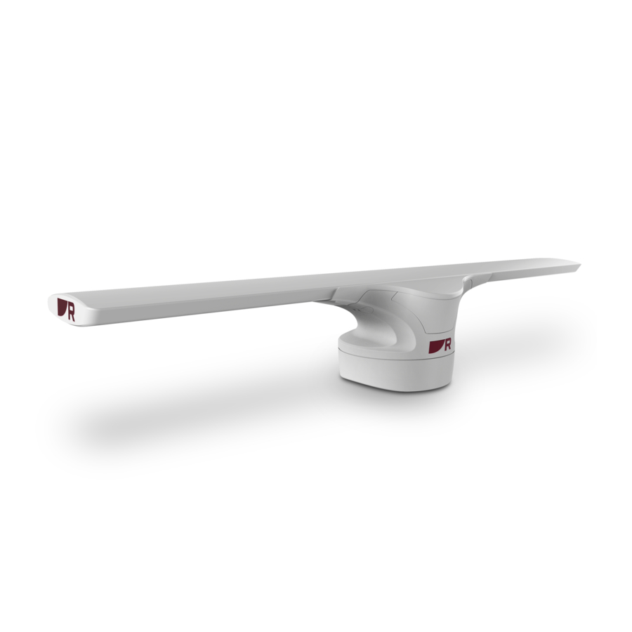
Page 22: Cyclone Open Array Radar
3.1 Cyclone Open Array Radar The Cyclone Open Array Radar is a Solid State open array radar. Cyclone provides a map-like representation of an extended area around your vessel, enabling you to identify birds, weather, other vessels, and land features such as coastlines and hills. -
Page 23: Vcm100 Voltage Converter Module
Important: • The VCM100 is an essential component in your radar’s system and MUST be used to supply power to the Cyclone radar. The model number of the VCM100 that is suitable for use with the Cyclone Radar is: E70648. -
Page 24: Lighthouse Mfd Software Requirements
3.4 Lighthouse MFD software requirements To use this product with a Raymarine LightHouse™ 3 MFD, ensure that your MFD is running at least software version 3.14. Note: The latest MFD software can be obtained by visiting www.raymarine.com/software. 3.5 Required additional components This product forms part of a system of electronics and requires the following additional components for full operation. -
Page 25: Chapter 4 Parts Supplied
Chapter 4: Parts supplied Chapter contents • 4.1 Parts supplied (pedestal) on page 26 • 4.2 Parts supplied (antenna) on page 27 • 4.3 Parts supplied (VCM100) on page 27 Parts supplied... -
Page 26: Parts Supplied (Pedestal)
4.1 Parts supplied (pedestal) Parts illustrated are supplied in the pedestal box: Radar Pedestal 2. M10 Stud x4 3. M10 Nut x8 4. M10 Spring Washer x4 5. M10 Plain Washer x4 6. Mounting Gasket Mounting Template 8. Radar Data Cable 9. -
Page 27: Parts Supplied (Antenna)
4.2 Parts supplied (antenna) Parts illustrated are supplied in the antenna box: Radar Antenna 2. M8 Hex Bolt x4 3. M8 Plain Washer x4 4. M8 Spring Washer x4 5. O Ring x4 4.3 Parts supplied (VCM100) Parts illustrated are supplied in the VCM100 box: VCM100 2. -
Page 29: Chapter 5 Product Dimensions
Chapter 5: Product dimensions Chapter contents • 5.1 Cyclone series on page 30 • 5.2 VCM100 Voltage Convertor Module on page 30 Product dimensions... -
Page 30: Cyclone Series
5.1 Cyclone series A — Antenna size is determined by model: • E70628 – (36 in array) – 1031 mm (40.5 in) • E70629 – (48 in array) – 1336 mm (52.5 in) • E70630 – (72 in array) – 1945 mm (76.5 in) 5.2 VCM100 Voltage Convertor Module... -
Page 31: Chapter 6 Location Requirements
Chapter 6: Location requirements Chapter contents • 6.1 Potential ignition source on page 32 • 6.2 Radar position overview on page 32 • 6.3 Radar scanner general location requirements on page 32 • 6.4 Compass safe distance on page 34 •... -
Page 32: Potential Ignition Source
6.2 Radar position overview The optimum height for the Cyclone radar is a location that is high enough above the waterline to give a long range line-of-sight to the horizon, but not so high as to be adversely affected by the vessel's pitching and rolling. - Page 33 • Mount the scanner above head height out of range of personnel, to avoid mechanical danger and minimize exposure to electromagnetic radiation. • Radar operates at the line-of-sight, so a high mounting position gives better long range performance. • Surrounding large objects, in the same horizontal plane, can interfere with the radar signal and cause blind areas or shadow sectors and false targets on the radar display (see below).
-
Page 34: Compass Safe Distance
Cables • All cables should be adequately clamped and protected from physical damage and exposure to heat. Avoid running cables through bilges or doorways, or close to moving or hot objects. • Where a cable passes through an exposed bulkhead or deckhead, use a watertight feed-through. 6.4 Compass safe distance To prevent potential interference with the vessel's magnetic compasses, ensure an adequate distance is maintained from the product. -
Page 35: Multiple Radar Scanners - Location Requirements
Wedge or washers 6.6 Multiple Radar scanners — location requirements Important location considerations when installing multiple radar scanners on the same vessel. • Scanners should be mounted above each other, vertically separated by at least 0.5 m (1.6 ft). This applies to all installation locations on the vessel. - Page 36 Power supply Select a location that is as close as possible to the vessel’s DC power source. This will help to keep cable runs to a minimum.
-
Page 37: Chapter 7 Cables And Connections
Chapter 7: Cables and connections Chapter contents • 7.1 General cabling guidance on page 38 • 7.2 Cyclone connections overview on page 39 • 7.3 Cable routing options on page 39 Cables and connections... -
Page 38: General Cabling Guidance
• Unless otherwise stated only use cables supplied by Raymarine. • Where it is necessary to use non-Raymarine cables, ensure that they are of correct quality and gauge for their intended purpose. (e.g.: longer power cable runs may require larger wire gauges to minimize voltage drop along the run). -
Page 39: Cable Shielding
Ensure that cable shielding is not damaged during installation and that all cables are properly shielded. 7.2 Cyclone connections overview The Cyclone Open Array Radar includes the following connectors: Power connector — Connects to the Cyclone power cable 2. RayNet connector — Connects to a (RayNet) Radar data cable 7.3 Cable routing options... -
Page 40: Rear Exit
Rear exit Mounting surface 2. Power and RayNet connectors 3. Power and RayNet cables... -
Page 41: Surface Exit
Surface exit Mounting surface 2. Power and RayNet connectors 3. Power and RayNet cables 4. Cable seal Note: The power and data cables should pass through the cable seal using the slits. The cable seal should then be fitted to the underside of the pedestal as shown. Cables and connections... -
Page 43: Chapter 8 Installation
Chapter 8: Installation Chapter contents • 8.1 Warnings and cautions on page 44 • 8.2 Schematic diagram on page 44 • 8.3 Tools required on page 44 • 8.4 Mounting on page 45 Installation... -
Page 44: Warnings And Cautions
8.1 Warnings and cautions Important: Before proceeding, ensure that you have read and understood the warnings and cautions provided in the Chapter 1 Important information section of this document. 8.2 Schematic diagram A schematic diagram is an essential part of planning any installation. It is also useful for any future additions or maintenance of the system. -
Page 45: Mounting
8.4 Mounting Cyclone Mounting the pedestal Before mounting the unit, ensure that you have: • Selected a suitable location. • Identified the cable connections and route that the cables will take. Important: Prepared suitable lifting equipment for fixing the pedestal to the mounting platform. The lifting... - Page 46 6. Remove the mounting template. 7. The pedestal has a transit cover fitted over the open array. This cover must be left in place until the open array antenna is fitted to the pedestal. 8. Insert the studs no more than 11 mm into the holes in the pedestal base, and hand-tighten. If the supplied studs are not long enough for the mounting surface thickness, use M10 stainless steel, grade A4-70 studding of a suitable length.
- Page 47 10. Lift the pedestal up and connect the power and data cables to the connectors on the underside of the pedestal. Organise the cables in accordance with your planned cable routing and place the pedestal back into position. Important: For more information refer to p.37 —...
- Page 48 13. Ensure all 4 sets of nuts and washers are used to secure the pedestal to the mounting platform. There should be no more than 6 mm of excess stud below the nut. Cut-off any excess stud. Attaching the antenna Before attaching the antenna to the pedestal unit, ensure that: •...
- Page 49 Important: Take care not to damage the open array’s delicate contacts when removing the cover. 2. Referring to the following illustration, lower the antenna onto the pedestal, placing the front on first and clipping it in place. 3. Using the 4 hex bolts and associated washers and O rings, secure the antenna to the pedestal. Tighten each nut to 10 N m (7.4 lb ft).
-
Page 50: Mounting The Vcm100
Radar scanner unit or the bracket. • Raymarine strongly recommends that you check the condition and security of the bracket mounting feet, the security lanyard(s), the Radar scanner guard, and the Radar scanner unit itself, on a yearly basis (or more frequently depending on environmental applications). - Page 51 1. Check the selected location for the unit. The VCM100 requires a clear, flat area with suitable space for routing the cables below the unit. 2. Hold the VCM100 in place in the required mounting location. 3. Using a pencil, mark the drilling area inside the mounting lug on each side of the VCM100 unit. 4.
-
Page 53: Chapter 9 System Connections
Chapter 9: System connections Chapter contents • 9.1 Typical system examples on page 54 System connections... -
Page 54: Typical System Examples
9.1 Typical system examples The Cyclone Open Array Radar scanner can be connected to a variety of equipment as part of your marine electronics system. Note: The following illustrations show the various products that can be connected in a typical system. - Page 55 Some power connections are omitted from this illustration. The network switch and multifunction display each require a dedicated power connection. Important: Fuses (not supplied) are required for circuit protection for the Cyclone Radar: 12 V dc • 15 A thermal fuse at breaker (x1) •...
- Page 56 8. VCM100 power cable Radar connected directly to RayNet multifunction display Important: Fuses (not supplied) are required for circuit protection for the Cyclone Radar: 12 V dc • 15 A thermal fuse at breaker (x1) • 20 A inline fuse on RED power cable (x1) 24 V dc •...
- Page 57 6. MFD power cable 12 V dc / 24 V dc Power supply (Distribution Panel or Battery) 8. VCM100 power cable System connections...
-
Page 59: Chapter 10 Power Connections
Chapter 10: Power connections Chapter contents • 10.1 Radar power connections on page 60 Power connections... -
Page 60: Radar Power Connections
4. Power cable from vessel power supply to VCM100 (power cable not supplied) 5. Vessel power supply The Cyclone Open Array Radar is intended for use on vessel DC power systems operating at 12 or 24 Volts DC. • All power connections must be made via the VCM100 Voltage Converter Module. -
Page 61: Vcm100 Power Connections
Note: The maximum length for the radar power cable (including all extensions) is 25 m (82 ft). • The radar scanner must be connected to the POWER OUT terminals of the VCM100. • The screen (drain) strands of the radar scanner's power cable must be connected to one of the VCM100 SCREEN terminals. -
Page 62: Vcm100 Power Cable Extension
POWER OUT (Positive) — connect to the RED wire of the power and data digital cable. 2. POWER OUT (Negative) — connect to the BLACK wire of the power and data digital cable. 3. SCREEN — connect to the bare screen (drain) strands of the power and data digital cable. 4. -
Page 63: Vcm100 Screen (Drain) Wire Extension
VCM100 screen (drain) wire extension The screen (drain) wire can be extended for longer cable runs between the VCM100 and your vessel's RF ground system. Extensions to the screen (drain) wire should use an 8 mm braid or AWG 10 (5.26 mm ) multi-stranded cable. -
Page 65: Chapter 11 System Checks
Chapter 11: System checks Chapter contents • 11.1 Radar scanner initial power on test on page 66 • 11.2 Radar check on page 66 System checks... -
Page 66: Radar Scanner Initial Power On Test
11.1 Radar scanner initial power on test With all cables correctly and securely connected to the radar scanner, and access to a multifunction display (power OFF): 1. Ensure the radar scanner power switch is set to ON. 2. Power on the multifunction display. The radar scanner should enter Standby mode. -
Page 67: Check And Adjust Bearing Alignment
Typical Typical radar Typical radar screen radar screen screen Points to to to check: check: Points Points check: • Radar sweep with echo responses are shown on screen. • Radar status icon rotating in top right hand corner. Check and adjust bearing alignment Bearing alignment The Radar bearing alignment ensures that Radar objects appear at the correct bearing relative to your boat’s bow. - Page 68 Example misaligned Radar Target object (such as a buoy) dead ahead. 2. Target displayed on the Radar display is not aligned with the Ship's Heading Marker (SHM). Bearing alignment is required. Checking the bearing alignment 1. With your vessel under way: Align the bow with a stationary object identified on the Radar display An object between 1 &...
-
Page 69: Chapter 12 Operation
Chapter 12: Operation Chapter contents • 12.1 Operation instructions on page 70 Operation... -
Page 70: Operation Instructions
12.1 Operation instructions For detailed operation instructions for your product, refer to the documentation that accompanies your display. All product documentation is available to download from the Raymarine website: www.raymarine.com/manuals • 81370 — LightHouse 3 MFD Advanced Operation Instructions... -
Page 71: Chapter 13 Troubleshooting
Chapter 13: Troubleshooting Chapter contents • 13.1 Troubleshooting on page 72 • 13.2 Power up troubleshooting on page 73 • 13.3 Radar troubleshooting on page 74 • 13.4 Radar target acquisition data source requirements on page 75 • 13.5 Doppler data source requirements on page 75 •... -
Page 72: Troubleshooting
If after referring to this section you are still having problems with your product, please refer to the Technical support section of this manual for useful links and Raymarine Product Support contact details. -
Page 73: Power Up Troubleshooting
In the unlikely event that the product’s software has become corrupted, try downloading and installing the latest software from the Raymarine website. 2. On display products, as a last resort, attempt to perform a ‘Power on Reset’. Be aware that this will delete all settings / presets and user data (such as waypoints and tracks), and revert the unit back to factory defaults. -
Page 74: Radar Troubleshooting
(this can cause the unit to reset/turn off), replace if necessary. 6. Check condition of relevant breakers and fuses, replace if necessary. . If breaker keeps tripping or fuses keep blowing, contact a Raymarine authorized dealer for assistance. Open Array Ensure Open Array power switch is in ON position. -
Page 75: Radar Target Acquisition Data Source Requirements
13.4 Radar target acquisition data source requirements Radar target acquisition requires the following data sources to be available on your system (e.g. connected to your multifunction display, via SeaTalkng ® or NMEA 0183). Data type Example data source COG (Course Over Ground) GPS or GNSS receiver (MFD internal receiver or external receiver). -
Page 76: Vcm100 Led Indications
13.6 VCM100 LED indications LED indications associated with the VCM100. LED name LED color / state Possible causes Green / solid Radar operating normally. Fault Red / solid Fault condition. Sleep Yellow / flashing Radar scanner in standby. Yellow / solid Fault condition, unit self-recovers after 20 seconds. -
Page 77: Chapter 14 Technical Support
Chapter 14: Technical support Chapter contents • 14.1 Raymarine product support and servicing on page 78 Technical support... -
Page 78: Raymarine Product Support And Servicing
You can obtain this product information using diagnostic pages of the connected MFD. Servicing and warranty Raymarine offers dedicated service departments for warranty, service, and repairs. Don’t forget to visit the Raymarine website to register your product for extended warranty benefits: http://www.raymarine.co.uk/display/?id=788. United Kingdom (UK), EMEA, and Asia Pacific: •... - Page 79 • Tel: +358 (0)207 619 937 Norway (Raymarine subsidiary): • E-Mail: support.no@raymarine.com • Tel: +47 692 64 600 Denmark (Raymarine subsidiary): • E-Mail: support.dk@raymarine.com • Tel: +45 437 164 64 Russia (Authorized Raymarine distributor): • E-Mail: info@mikstmarine.ru • Tel: +7 495 788 0508 Technical support...
-
Page 81: Chapter 15 Technical Specification
Chapter 15: Technical specification Chapter contents • 15.1 Technical specification on page 82 Technical specification... -
Page 82: Technical Specification
15.1 Technical specification Approvals Approvals Certification 47CFR Part 80 Certificate of Approval Cyclone: FCC ID: PJ5 -953LPSSR Cyclone Pro: FCC ID: PJ5 -953MPSSR Canada RSS138 Iss. 1 Technical Acceptance Certificate Cyclone: IC:4069B-953LPSSR Cyclone Pro: IC:4069B-953MPSSR European Union & EFTA Radio Equipment Directive 2014/53/EU... - Page 83 Connectors Cyclone (E70620) Cyclone Pro (E70621) Power connection 1x Power connector 1x Power connector Data connection 1x RayNet connector 1x RayNet connector Range Range (Nm) Pulse width (ns) PRF (Khz) 1/16 1020 1 1/2 1235 1675 2300 2710 3900 3900...
-
Page 85: Chapter 16 Spares And Accessories
Chapter 16: Spares and accessories Chapter contents • 16.1 Accessories on page 86 • 16.2 Network hardware on page 86 • 16.3 RayNet to RayNet cables and connectors on page 87 Spares and accessories... -
Page 86: Accessories
16.1 Accessories The following accessories are available for your product Accessories Item Part number Cyclone Power Cable 5M A80651 Cyclone Power Cable 10M A80652 Cyclone Power Cable 15M A80653 Cyclone Power Cable 25M A80654 Radar Data Cable 5M A80657 Radar Data Cable 10M... -
Page 87: Raynet To Raynet Cables And Connectors
16.3 RayNet to RayNet cables and connectors Standard RayNet connection cable with a RayNet (female) socket on both ends. 2. Right-angle RayNet connection cable with a straight RayNet (female) socket on one end, and a right-angle RayNet (female) socket on the other end. Suitable for connecting at 90° (right angle) to a device, for installations where space is limited. - Page 89 Data source requirements ......24, 75 Maintenance............10 MARPA Data source requirements ......24, 75 Mounting ..............45 Bearing alignment ..........67–68 Antenna ...............48 Cyclone............45, 48 Pedestal ...............45 Multifunction display Cable Compatibility ............23 Bend radius............38 Multiple scanners ............22 Protection ............. 38–39 Rear exit...............40...
- Page 90 Service Center............78 Servicing..............10 System checks Bearing alignment..........67 System connections ..........53 System examples ............54 Technical specification ........81–82 Technical support............ 78 Troubleshooting ............72 VCM100 ..............55 Applicable products..........16 Dimensions ............30 mounting.............. 51 Parts supplied ............27 Power connection..........60 Product overview..........23 Warranty ..............
- Page 92 Raymarine Marine House, Cartwright Drive, Fareham, Hampshire. PO15 5RJ. United Kingdom. Tel: +44 (0)1329 246 700 www.raymarine.com a brand by...