HP Compaq 6005 Pro Maintenance And Service Manual
Business pc ultra-slim desktop
Hide thumbs
Also See for Compaq 6005 Pro:
- Maintenance & service manual (259 pages) ,
- Hardware reference manual (62 pages) ,
- Specification (57 pages)
Table of Contents
Advertisement
Quick Links
Advertisement
Table of Contents

Related Manuals for HP Compaq 6005 Pro


Summary of Contents for HP Compaq 6005 Pro
- Page 1 Maintenance and Service Guide HP Compaq 6005 Pro Business PC Ultra-slim Desktop...
- Page 2 Microsoft and Windows are trademarks of Microsoft Corporation in the U.S. and other countries. The only warranties for HP products and services are set forth in the express warranty statements accompanying such products and services. Nothing herein should be construed as constituting an additional warranty.
-
Page 3: About This Book
About This Book WARNING! Text set off in this manner indicates that failure to follow directions could result in bodily harm or loss of life. CAUTION: Text set off in this manner indicates that failure to follow directions could result in damage to equipment or loss of information. - Page 4 About This Book...
-
Page 5: Table Of Contents
Table of contents 1 Product Features ............................1 Front Panel Components ........................1 Rear Panel Components ........................2 2 Installing and Customizing the Software ...................... 3 Installing the Windows Operating System .................... 3 Downloading Microsoft Windows Updates ................... 4 Installing or Upgrading Device Drivers (Windows systems) ..............4 Customizing the Monitor Display (Windows systems) ................ - Page 6 Preparation for Disassembly ......................31 Serial Number Location ........................32 Security Lock Provisions ........................33 Installing a Security Lock ....................33 HP/Kensington MicroSaver Security Cable Lock ..........33 Padlock ......................34 HP Business PC Security Lock ................. 35 Front Bezel Security ..................37 Port Cover ............................
- Page 7 Hard Drive ............................51 Hard Drive Cage ..........................55 Front Fan ............................56 Card Reader ............................57 Hood sensor ............................58 Speaker .............................. 59 Heat sink ............................60 TV Tuner Module ..........................61 Processor ............................63 System Board ............................. 64 Rear Fan ............................
- Page 8 History Tab ........................90 Errors Tab .......................... 90 Help Tab ..........................91 Saving and Printing Information in HP Vision Diagnostics ..........91 Downloading the Latest Version of HP Vision Diagnostics ..........91 Protecting the Software ........................92 Appendix E Troubleshooting Without Diagnostics ..................93 Safety and Comfort ..........................
- Page 9 Appendix G Password Security and Resetting CMOS ................136 Resetting the Password Jumper ...................... 137 Clearing and Resetting the CMOS ....................138 Appendix H Drive Protection System (DPS) ....................139 Accessing DPS Through Computer Setup ..................139 Appendix I Specifications ..........................141 Index .................................
-
Page 11: Product Features
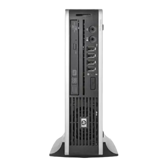
Product Features Front Panel Components Drive configuration may vary by model. Figure 1-1 Front Panel Components Table 1-1 Front Panel Components Optical Drive Microphone/Headphone Connector System Power LED USB (Universal Serial Bus) Ports SD Media Card Reader (optional) Hard Drive Activity Light Headphone Connector Dual-State Power Button NOTE:... -
Page 12: Rear Panel Components
Rear Panel Components Figure 1-2 Rear Panel Components Table 1-2 Rear Panel Components Line-Out Connector for powered audio Power Cord Connector devices (green) PS/2 Keyboard Connector (purple) TV Tuner (optional) Universal Serial Bus (USB) (6) Line-In Audio Connector (blue) DisplayPort Monitor Connector PS/2 Mouse Connector (green) VGA Monitor Connector (blue) RJ-45 Network Connector... -
Page 13: Installing And Customizing The Software
If the computer was shipped with Windows Vista or Windows 7 loaded, you will be prompted to register the computer with HP Total Care before installing the operating system. You will see a brief movie followed by an online registration form. Fill out the form, click the Begin button, and follow the instructions on the screen. -
Page 14: Downloading Microsoft Windows Updates
Obtain the latest support software, including support software for the operating system from http://www.hp.com/support. Select your country and language, select Download drivers and software (and firmware), enter the model number of the computer, and press Enter. Customizing the Monitor Display (Windows systems) If you wish, you can select or change the monitor model, refresh rates, screen resolution, color settings, font sizes, and power management settings. -
Page 15: Launching Windows Xp From Windows 7
Launching Windows XP from Windows 7 Windows XP Mode for Windows 7 allows you to install and launch Windows XP applications from the Windows 7 taskbar. This feature is available on some computer models only. To set up from a pre-installed Windows 7 desktop, click Start > Windows Virtual PC > Virtual Windows XP and follow the instructions on the screen. -
Page 16: Accessing Disk Image (Iso) Files
● Corel WinDVD SD and BD – installation software for WinDVD – used to play DVD movies ● HP Insight Diagnostics OR Vision Diagnostics – software to perform diagnostic activities on your Chapter 2 Installing and Customizing the Software... -
Page 17: Computer Setup (F10) Utility
Computer Setup (F10) Utility Computer Setup (F10) Utilities Use Computer Setup (F10) Utility to do the following: ● Change system default settings. ● Set the system date and time. ● Set, view, change, or verify the system configuration, including settings for processor, graphics, memory, audio, storage, communications, and input devices. -
Page 18: Using Computer Setup (F10) Utilities
● Solve system configuration errors detected but not automatically fixed during the Power-On Self- Test (POST). ● Replicate the system setup by saving system configuration information on USB flash media device or other storage media emulating a diskette and restoring it on one or more computers. ●... -
Page 19: Computer Setup-File
Computer Setup—File NOTE: Support for specific Computer Setup options may vary depending on the hardware configuration. Table 3-2 Computer Setup—File Option Description System Information Lists: ● Product name ● SKU number (some models) ● Processor type/speed/stepping ● Cache size (L1/L2/L3) ●... -
Page 20: Computer Setup-Storage
Computer Setup—Storage NOTE: Support for specific Computer Setup options may vary depending on the hardware configuration. Chapter 3 Computer Setup (F10) Utility... - Page 21 Table 3-3 Computer Setup—Storage Option Description Device Configuration Lists all installed BIOS-controlled storage devices. When a device is selected, detailed information and options are displayed. The following options may be presented. Emulation Type Allows you to select a drive emulation type for a certain storage device. (For example, a Zip drive can be made bootable by selecting diskette emulation.) Drive Emulation Type Options ATAPI Zip drive:...
- Page 22 Table 3-3 Computer Setup—Storage (continued) Option Description Storage Options Removable Media Boot Enables/disables ability to boot the system from removable media. SATA Emulation Allows you to choose how the SATA controller and devices are accessed by the operating system. There are up to three supported options: Legacy Mode IDE, Native Mode IDE, and AHCI.
-
Page 23: Computer Setup-Security
Computer Setup—Security NOTE: Support for specific Computer Setup options may vary depending on the hardware configuration. Table 3-4 Computer Setup—Security Option Description Setup Password Allows you to set and enable setup (administrator) password. NOTE: If the setup password is set, it is required to change Computer Setup options, flash the ROM, and make changes to certain plug and play settings under Windows. - Page 24 Table 3-4 Computer Setup—Security (continued) Option Description USB Security Allows you to disable individual or groups (Front, Rear, and Accessory) of USB ports. NOTE: The media card reader is connected to the Accessory port. Slot Security Allows you to disable the PCIe slot along with the card plugged into it. Network Service Boot Enables/disables the computer’s ability to boot from an operating system installed on a network server.
- Page 25 Table 3-4 Computer Setup—Security (continued) Option Description System Security Data Execution Prevention (some models) (enable/disable) Helps prevent operating system (some models: these security breaches. options are hardware Virtualization Technology (some models) (enable/disable) Controls the virtualization features of dependent) the processor. Changing this setting requires turning the computer off and then back on. Embedded Security Device Support (some models) (enable/disable) Permits activation and deactivation of the Embedded Security Device.
-
Page 26: Computer Setup-Power
Computer Setup—Power NOTE: Support for specific Computer Setup options may vary depending on the hardware configuration. Table 3-5 Computer Setup—Power Option Description ● OS Power Idle Power Savings—Extended/Normal. Allows certain operating systems to decrease the Management processor's power consumption when the processor is idle. ●... - Page 27 Table 3-6 Computer Setup—Advanced (for advanced users) Option Description Power-On Options Allows you to set: ● POST mode (QuickBoot, Clear Memory, FullBoot, or FullBoot Every x Days). ◦ QuickBoot = Do not clear memory or perform a memory test. ◦ FullBoot = Memory test (count) on cold boot.
- Page 28 Table 3-6 Computer Setup—Advanced (for advanced users) (continued) Option Description ◦ Clear Memory = No memory count on cold boot. Clears memory on all boots. ◦ FullBoot Every x Days = Memory count on 1st cold boot on or after the xth day. No more memory counts until 1st cold boot on or after x days.
- Page 29 Table 3-6 Computer Setup—Advanced (for advanced users) (continued) Option Description BIOS Power-On Allows you to set the computer to turn on automatically at a time you specify. PCI Devices ● Lists currently installed PCI devices and their IRQ settings. ● Allows you to reconfigure IRQ settings for these devices or to disable them entirely.
-
Page 30: Recovering The Configuration Settings
Table 3-6 Computer Setup—Advanced (for advanced users) (continued) Option Description controller from being used by the operating system and reduces the power used by the computer in S5. ● Processor cache (enable/disable). ● Multi-Processor (enable/disable). This option may be used to disable multi-processor support under the OS. -
Page 31: Serial Ata (Sata) Drive Guidelines And Features
3.0 Gb/s SATA Hard Drive Cables SATA Data Cable Always use an HP approved SATA 3.0 Gb/s cable as it is fully backwards compatible with the SATA 1.5 Gb/s drives. Current HP desktop products ship with SATA 3.0 Gb/s hard drives. -
Page 32: Smart Ata Drives
SMART ATA Drives The Self Monitoring Analysis and Recording Technology (SMART) ATA drives for the HP Personal Computers have built-in drive failure prediction that warns the user or network administrator of an impending failure or crash of the hard drive. The SMART drive tracks fault prediction and failure indication parameters such as reallocated sector count, spin retry count, and calibration retry count. -
Page 33: Identifying The Chassis, Routine Care, And Disassembly Preparation
Identifying the Chassis, Routine Care, and Disassembly Preparation This chapter provides general service information for the computer. Adherence to the procedures and precautions described in this chapter is essential for proper service. CAUTION: When the computer is plugged into an AC power source, voltage is always applied to the system board. -
Page 34: Electrostatic Discharge Information
Electrostatic Discharge Information A sudden discharge of static electricity from your finger or other conductor can destroy static- sensitive devices or microcircuitry. Often the spark is neither felt nor heard, but damage occurs. An electronic device exposed to electrostatic discharge (ESD) may not appear to be affected at all and can work perfectly throughout a normal cycle. -
Page 35: Personal Grounding Methods And Equipment
● Keep electrostatic sensitive parts in their containers until they arrive at static-free stations. ● Place items on a grounded surface before removing them from their container. ● Always be properly grounded when touching a sensitive component or assembly. ● Avoid contact with pins, leads, or circuitry. -
Page 36: Recommended Materials And Equipment
Recommended Materials and Equipment Materials and equipment that are recommended for use in preventing static electricity include: ● Antistatic tape ● Antistatic smocks, aprons, or sleeve protectors ● Conductive bins and other assembly or soldering aids ● Conductive foam ● Conductive tabletop workstations with ground cord of one-megohm +/- 10% resistance ●... -
Page 37: Routine Care
● Do not stack computers on top of each other or place computers so near each other that they are subject to each other’s re-circulated or preheated air. ● If the computer is to be operated within a separate enclosure, intake and exhaust ventilation must be provided on the enclosure, and the same operating guidelines listed above will still apply. -
Page 38: Cleaning The Keyboard
Cleaning the Keyboard Follow all safety precautions in General Cleaning Safety Precautions on page 27 before cleaning the keyboard. To clean the tops of the keys or the keyboard body, follow the procedures described in Cleaning the Computer Case on page When cleaning debris from under the keys, review all rules in General Cleaning Safety Precautions on page 27... -
Page 39: Power Supply Fan
If an incorrect screw is used during the reassembly process, it can damage the unit. HP strongly recommends that all screws removed during disassembly be kept with the part that was removed, then returned to their proper locations. -
Page 40: Hard Drives
In order to forward them to recycling or proper disposal, please use the public collection system or return them to HP, their authorized partners, or their agents. Chapter 5 Identifying the Chassis, Routine Care, and Disassembly Preparation... -
Page 41: Removal And Replacement Procedures
Removal and Replacement Procedures Adherence to the procedures and precautions described in this chapter is essential for proper service. After completing all necessary removal and replacement procedures, run the Diagnostics utility to verify that all components operate properly. NOTE: Not all features listed in this guide are available on all computers. Preparation for Disassembly Identifying the Chassis, Routine Care, and Disassembly Preparation on page 23 for initial safety... -
Page 42: Serial Number Location
Serial Number Location Each computer has a unique serial number and a product ID that are located on the top of the computer when it is in the tower configuration. Keep these numbers available for use when contacting customer service for assistance. Figure 6-1 Serial Number and Product ID Location Chapter 6 Removal and Replacement Procedures... -
Page 43: Security Lock Provisions
NOTE: For information on data security features, refer to the Desktop Management Guide and the HP ProtectTools Security Manager Guide (some models) at http://www.hp.com. The security locks displayed below and on the following pages can be used to secure the computer. -
Page 44: Padlock
Figure 6-3 Installing a Cable with a Port Cover Installed Padlock Figure 6-4 Installing a Padlock Chapter 6 Removal and Replacement Procedures... -
Page 45: Hp Business Pc Security Lock
HP Business PC Security Lock Fasten the security cable by looping it around a stationary object. Figure 6-5 Securing the Cable to a Fixed Object Thread the keyboard and mouse cables through the lock. Figure 6-6 Threading the Keyboard and Mouse Cables... - Page 46 Screw the lock to the chassis using the screw provided. Figure 6-7 Attaching the Lock to the Chassis Insert the plug end of the security cable into the lock (1) and push the button in (2) to engage the lock. Use the key provided to disengage the lock. Figure 6-8 Engaging the Lock Chapter 6 Removal and Replacement Procedures...
-
Page 47: Front Bezel Security
Front Bezel Security The front bezel can be locked in place by installing a security screw provided by HP. To install the security screw: Remove/disengage any security devices that prohibit opening the computer. Remove all removable media, such as compact discs or USB flash drives, from the computer. - Page 48 Install the security screw through the middle front bezel release tab and into the chassis to secure the front bezel in place. Figure 6-10 Installing the Front Bezel Security Screw Replace the access panel. If the computer was on a stand, replace the stand. Reconnect the power cord and turn on the computer.
-
Page 49: Port Cover
Port Cover An optional rear port cover is available for the computer. To install the port cover: Thread the cables through the bottom hole on the port cover (1) and connect the cables to the rear ports on the computer. Insert the hooks on the port cover into the slots on the rear of the chassis, then slide the cover to the right to secure it in place (2). -
Page 50: Computer Access Panel
Computer Access Panel To access internal components, you must remove the access panel: Prepare the computer for disassembly (Preparation for Disassembly on page 31). Loosen the thumbscrew on the rear of the computer (1), slide the access panel toward the front of the computer, and then lift it off (2). -
Page 51: Front Bezel
Front Bezel Prepare the computer for disassembly (Preparation for Disassembly on page 31). Remove the computer access panel (Computer Access Panel on page 40). Lift up the three tabs on the side of the bezel (1), then rotate the bezel off the chassis (2). Figure 6-14 Removing the Front Bezel To install the front bezel, reverse the removal procedure. -
Page 52: Bezel Blank
Bezel Blank On some models, there is a bezel blank covering the external drive bay that needs to be removed before installing a drive. To remove a bezel blank: Remove the computer access panel (Computer Access Panel on page 40). Remove the front bezel (Front Bezel on page 41). -
Page 53: Installing Additional Memory
Installing Additional Memory The computer comes with double data rate 3 synchronous dynamic random access memory (DDR3- SDRAM) small outline dual inline memory modules (SODIMMs). SODIMMs The memory sockets on the system board can be populated with up to two industry-standard SODIMMs. -
Page 54: Populating Sodimm Sockets
Populating SODIMM Sockets There are two SODIMM sockets on the system board, with one socket per channel. The sockets are labeled DIMM1 and DIMM2. Figure 6-16 SODIMM Socket Locations Table 6-1 SODIMM Socket Locations Item Description Socket Color DIMM1 socket Black DIMM2 socket White... - Page 55 Locate the memory module sockets on the system board. WARNING! To reduce risk of personal injury from hot surfaces, allow the internal system components to cool before touching. If you are removing a SODIMM, press outward on the two latches on each side of the SODIMM (1) then pull the SODIMM out of the socket (2).
- Page 56 To install a SODIMM, slide the new SODIMM into the socket at approximately a 30° angle (1) then press the SODIMM down (2) so that the latches lock it in place. Figure 6-18 Installing a SODIMM NOTE: A memory module can be installed in only one way. Match the notch on the module with the tab on the memory socket.
-
Page 57: Cable Management
Cable Management Always follow good cable management practices when working inside the computer. ● Keep cables away from major heat sources like the heat sink. ● Do not jam cables on top of expansion cards or memory modules. Printed circuit cards like these are not designed to take excessive pressure on them. -
Page 58: Replacing The Optical Drive
Replacing the Optical Drive The Ultra-Slim Desktop uses a slimline Serial ATA (SATA) optical drive. Removing the Existing Optical Drive Prepare the computer for disassembly (Preparation for Disassembly on page 31). If the computer is on a stand, remove the computer from the stand and lay the computer down. Remove the computer access panel (Computer Access Panel on page 40). -
Page 59: Preparing The New Optical Drive
Preparing the New Optical Drive Before the new optical drive can be used, the release latch must be attached. Peel the backing off the adhesive on the release latch. Without allowing the release latch to touch the optical drive, carefully align the holes on the release latch with the pins on the side of the optical drive. -
Page 60: Installing The New Optical Drive
Installing the New Optical Drive NOTE: If you are installing an optical drive in a bay that did not previously have a drive in it, you must remove the access panel and the bezel blank covering the opening of the bay before proceeding. -
Page 61: Hard Drive
Hard Drive NOTE: The Ultra-Slim Desktop supports only 2.5-inch Serial ATA (SATA) internal hard drives; parallel ATA (PATA) internal hard drives are not supported. Before you remove the old hard drive, be sure to back up the data from the old hard drive so that you can transfer the data to the new hard drive. - Page 62 Lift the hard drive carrier straight up and out of the chassis. Figure 6-23 Removing the Hard Drive Carrier Remove the four guide screws from the sides of the hard drive carrier. Figure 6-24 Removing the Guide Screws Lift the hard drive up to the top of the carrier (1) and slide the drive out of the carrier (2). Figure 6-25 Removing the Hard Drive from the Carrier Chapter 6 Removal and Replacement Procedures...
- Page 63 Position the hard drive so that the top of the hard drive is up against the top of the carrier (1) so that the circuit board on the bottom of the hard drive does not come in contact wit the tabs on the bottom of the carrier, then slide the new hard drive into the carrier (2).
- Page 64 To place the hard drive carrier back in the chassis, align the guide screws with the slots on the drive bay, drop the carrier straight down into the drive bay (1), and press the handle on the carrier all the way down (2) so that the drive is properly seated and locked in place. Figure 6-28 Installing the Hard Drive Carrier Replace the optical drive and reconnect the cable on the back of the optical drive.
-
Page 65: Hard Drive Cage
Hard Drive Cage The drive cage sits behind the USB ports on the front of the chassis. Prepare the computer for disassembly (Preparation for Disassembly on page 31). Remove the computer access panel (Computer Access Panel on page 40). Remove the optical drive and connector (Removing the Existing Optical Drive on page 48). -
Page 66: Front Fan
Front Fan The front fan sits against the front on the left side of the chassis. Prepare the computer for disassembly (Preparation for Disassembly on page 31). Remove the computer access panel (Computer Access Panel on page 40). Disconnect the fan control cable from the maroon system board connector labeled CHFAN_FRONT. -
Page 67: Card Reader
Card Reader The card reader is secured to the front right corner of the chassis. Prepare the computer for disassembly (Preparation for Disassembly on page 31). Remove the computer access panel (Computer Access Panel on page 40). Remove the front bezel (Front Bezel on page 41). -
Page 68: Hood Sensor
Hood sensor The hood sensor is secured in a slot in the top of the chassis. Prepare the computer for disassembly (Preparation for Disassembly on page 31). Remove the computer access panel (Computer Access Panel on page 40). Remove the front bezel (Front Bezel on page 41). -
Page 69: Speaker
Speaker The speaker is secured to the front of the chassis between the fan and the I/O ports. Prepare the computer for disassembly (Preparation for Disassembly on page 31). Remove the computer access panel (Computer Access Panel on page 40). Remove the front bezel (Front Bezel on page 41). -
Page 70: Heat Sink
Heat sink The heat sink is secured by four Torx T15 screws. It does not have an attached fan. Prepare the computer for disassembly (Preparation for Disassembly on page 31). Remove the computer access panel (Computer Access Panel on page 40). -
Page 71: Tv Tuner Module
If using a new heat sink, remove the protective covering from the bottom of the heat sink and place it in position atop the processor. Secure the heat sink to the system board and system board tray with the 4 captive screws and attach the heat sink control cable and the thermal sensor cable to the system board. - Page 72 To install the TV tuner module, reverse the removal procedure. Make sure the antenna cable is correctly routed over the speaker and in the clips mounted on the inside chassis wall. Chapter 6 Removal and Replacement Procedures...
-
Page 73: Processor
Processor Prepare the computer for disassembly (Preparation for Disassembly on page 31). Remove the computer access panel (Computer Access Panel on page 40). Remove the heat sink (Heat sink on page 60). Rotate the processor locking lever to its full open position (1). Carefully lift the processor from the socket (2). -
Page 74: System Board
After installing a new processor onto the system board, always update the system ROM to ensure that the latest version of the BIOS is being used on the computer. The latest system BIOS can be found on the Web at: http://h18000.www1.hp.com/support/files. System Board... - Page 75 Press the tab on right side of the cage (2), and then swing the right side of the cage away from the chassis to remove it (3). NOTE: If the cage sticks and will not come loose, press down on the top of the panel near the tab while pressing the tab.
- Page 76 Slide system board toward the front of the unit until the rear connectors are clear of their slots in the chassis (2). Figure 6-38 Removing the system board Lift the rear of the system board until it clears the chassis, and then remove the system board from the chassis.
-
Page 77: Rear Fan
Rear Fan The rear fan is secured to the rear right corner of the chassis. You must remove the system board before you can remove the rear fan. Prepare the computer for disassembly (Preparation for Disassembly on page 31). Remove the computer access panel (Computer Access Panel on page 40). -
Page 78: Battery
Do not expose to temperatures higher than 140°F (60°C). Do not disassemble, crush, puncture, short external contacts, or dispose of in fire or water. Replace the battery only with the HP spare designated for this product. CAUTION: Before replacing the battery, it is important to back up the computer CMOS settings. - Page 79 Insert the new battery and position the clip back in place. NOTE: Battery holder appearance may vary. Figure 6-40 Removing the battery After the battery has been replaced, reverse the disassembly procedure. Plug in the computer and turn on power to the computer. Reset the date and time, your passwords, and any special system setups, using Computer Setup.
-
Page 80: Changing From Desktop To Tower Configuration
WARNING! To reduce potential safety issues, only the power supply provided with the computer, a replacement power supply provided by HP, or a power supply purchased as an accessory from HP should be used with the computer. Chapter 6 Removal and Replacement Procedures... -
Page 81: Appendix A Connector Pin Assignments
Connector Pin Assignments This appendix contains the pin assignments for many computer and workstation connectors. Some of these connectors may not be used on the product being serviced. Keyboard Connector and Icon Signal Data Unused Ground +5 VDC Clock Unused Mouse Connector and Icon Signal... -
Page 82: Ethernet Rj-45
Ethernet RJ-45 Connector and Icon Signal (+) Transmit Data (-) Transmit Data (+) Receive Data Unused Unused (-) Receive Data Unused Unused Connector and Icon Signal +5 VDC - Data + Data Ground Microphone Connector and Icon (1/8” miniphone) Signal 1 (Tip) Audio_left 1 2 3... -
Page 83: Line-In Audio
Line-in Audio Connector and Icon (1/8” miniphone) Signal 1 (Tip) Audio_In_Left 1 2 3 2 (Ring) Audio_In_Right 3 (Shield) Ground Line-out Audio Connector and Icon (1/8” miniphone) Signal 1 (Tip) Audio_Out_Left 1 2 3 2 (Ring) Audio_Out_Right 3 (Shield) Ground Line-in Audio... -
Page 84: Monitor
Monitor Connector and Icon Signal Signal Red Analog +5V (fused) Green Analog Ground Blue Analog Not used Not used DDC Serial Data Ground Horizontal Sync Ground Vertical Sync Ground DDC Serial Clock Ground DisplayPort Connector and Icon TOP ROW BOTTOM ROW Signal Type Pin Name Signal Type... -
Page 85: Sata Data And Power
Ground Hot Plug Detect ML Lane 0 (p) CONFIG CONFIG 1 ML Lane 0 (n) CONFIG CONFIG 2 Ground ML Lane 1 (p) ML Lane 3 (p) Ground ML Lane 1 (n) ML Lane 3 (n) Ground ML Lane 2 (p) AUX CH (p) ML Lane 2 (n) AUX CH (n) -
Page 86: Appendix B Power Cord Set Requirements
Power Cord Set Requirements The power supplies on some computers have external power switches. The voltage select switch feature on the computer permits it to operate from any line voltage between 100-120 or 220-240 volts AC. Power supplies on those computers that do not have external power switches are equipped with internal switches that sense the incoming voltage and automatically switch to the proper voltage. -
Page 87: Country-Specific Requirements
Country-Specific Requirements Additional requirements specific to a country are shown in parentheses and explained below. Country Accrediting Agency Country Accrediting Agency Australia (1) EANSW Italy (1) Austria (1) Japan (3) METI Belgium (1) CEBC Norway (1) NEMKO Canada (2) Sweden (1) SEMKO Denmark (1) DEMKO... -
Page 88: Appendix C Backup And Recovery
NOTE: For detailed instructions, perform a search for these topics in Help and Support. NOTE: In case of system instability, HP recommends that you print the recovery procedures and save them for later use. Backing up your information Recovery after a system failure is as complete as your most current backup. You should create system repair discs (select models only) and your initial backup immediately after software setup. - Page 89 Note the following when backing up: ● Store personal files in the Documents library, and back it up regularly. ● Back up templates that are stored in their associated programs. ● Save customized settings that appear in a window, toolbar, or menu bar by taking a screen shot of your settings.
-
Page 90: Performing A Recovery
Recovery disc (both purchased separately). For additional information, refer to the “Using a Windows 7 operating system DVD (purchased separately)” section in this guide. If the Windows partition and the HP Recovery partition are listed, restart the computer, and then press before the Windows operating system loads. -
Page 91: Using F11
The recovery tool reinstalls the operating system and HP programs and drivers that were installed at the factory. Software not installed at the factory must be reinstalled. - Page 92 Click Next. Select Repair your computer. Follow the on-screen instructions. Appendix C Backup and Recovery...
-
Page 93: Windows Vista - Backup And Recovery
NOTE: For detailed instructions, perform a search for these topics in Help and Support. NOTE: In case of system instability, HP recommends that you print the recovery procedures and save them for later use. Backing up your information Recovery after a system failure is as complete as your most current backup. You should create your initial backup immediately after software setup. -
Page 94: Performing A Recovery
The screen image is added to the document. Save the document. ● When backing up to discs, use any of the following types of discs (purchased separately): CD-R, CD-RW, DVD+R, DVD+R DL, DVD-R, DVD-R DL, or DVD±RW. The discs you use will depend on the type of optical drive installed in your computer. -
Page 95: Using F11
If possible, back up all personal files. If possible, check for the presence of the Windows partition and the HP Recovery partition. To find the partitions, select Start > Computer. -
Page 96: Using A Windows Vista Operating System Dvd (Purchased Separately)
Using a Windows Vista operating system DVD (purchased separately) If you are unable to boot (start up) your computer, you must purchase a Windows Vista operating system DVD to reboot the computer and repair the operating system. Make sure that your most recent backup (stored on discs or on an external drive) is easily accessible. -
Page 97: Appendix D Computer Diagnostic Features
The information in each screen of the utility can be saved as an html file and stored on a USB flash drive. Use HP Vision Diagnostics to determine if all the devices installed on the computer are recognized by the system and functioning properly. Running tests is optional but recommended after installing or connecting a new device. -
Page 98: Survey Tab
HP Vision Diagnostics. If running HP Vision Diagnostics, select the appropriate language and click Continue. In the End User License Agreement page, select Agree if you agree with the terms. The HP Vision Diagnostics utility launches with the Survey tab displayed. -
Page 99: Test Tab
Memory can not be tested from within the HP Vision Diagnostics application. To test the memory in your computer, you must exit HP Vision Diagnostics, boot to either the CD or USB flash drive and select HP Memory Test from the boot menu. -
Page 100: History Tab
● The Warranty ID is a unique error code associated with the specific error on your computer. When contacting the HP Support Center for assistance with a hardware failure, please be prepared to provide the Warranty ID. The Clear Errors button will clear the contents of the Error Log. -
Page 101: Help Tab
The Help tab contains a Vision Help section, and a Test Components section. This tab includes search and index features. You may also review the HP End User License Agreement (EULA), as well as the HP Vision Diagnostic application version information on this tab. -
Page 102: Protecting The Software
Click the Diagnostic link. Click the Hewlett-Packard Vision Diagnostics link. Click the Download button. NOTE: The download includes instructions on how to create the bootable CD or the bootable USB flash drive. Protecting the Software To protect software from loss or damage, you should keep a backup copy of all system software, applications, and related files stored on the hard drive. -
Page 103: Appendix E Troubleshooting Without Diagnostics
If you are having problems with the computer, try the appropriate solutions below to try to isolate the exact problem before calling for technical support. ● Run the HP diagnostic tool. ● Run the hard drive self-test in Computer Setup. -
Page 104: Helpful Hints
Helpful Hints on page 94 in this guide. To assist you in resolving problems online, HP Instant Support Professional Edition provides you with self-solve diagnostics. If you need to contact HP support, use HP Instant Support Professional Edition's online chat feature. Access HP Instant Support Professional Edition at: http://www.hp.com/... - Page 105 ● Wake the computer by pressing any key on the keyboard or pressing the power button. If the system remains in suspend mode, shut down the computer by pressing and holding the power button for at least four seconds then press the power button again to restart the computer. If the system will not shut down, unplug the power cord, wait a few seconds, then plug it in again.
-
Page 106: Solving General Problems
Solving General Problems You may be able to easily resolve the general problems described in this section. If a problem persists and you are unable to resolve it yourself or if you feel uncomfortable about performing the operation, contact an authorized dealer or reseller. WARNING! When the computer is plugged into an AC power source, voltage is always applied to the system board. - Page 107 There is no sound or sound volume is too low. Cause Solution System volume may be set low or muted. Check the F10 BIOS settings to make sure the internal system speaker is not muted (this setting does not affect the external speakers). Make sure the external speakers are properly connected and powered on and that the speakers' volume control is set correctly.
- Page 108 Poor performance is experienced. Cause Solution Some software applications, especially games, are stressful Lower the display resolution for the current application on the graphics subsystem or consult the documentation that came with the application for suggestions on how to improve performance by adjusting parameters in the application.
- Page 109 System does not power on and the LEDs on the front of the computer are not flashing. Cause Solution System unable to power on. Press and hold the power button for less than 4 seconds. If the hard drive LED turns green, then replace the system board.
-
Page 110: Solving Power Problems
Solving Power Problems Common causes and solutions for power problems are listed in the following table. Power supply shuts down intermittently. Cause Solution Power supply will not turn on because of internal power Contact an authorized service provider to replace the power supply fault. - Page 111 The incorrect external power supply adapter is being used. The USDT power supply adapter must be at 135W and use the Smart ID technology before the system will power up. Replace the power supply adapter with the HP-supplied USDT power supply adapter. Solving Power Problems...
-
Page 112: Solving Hard Drive Problems
Solving Hard Drive Problems Hard drive error occurs. Cause Solution Hard disk has bad sectors or has failed. In Microsoft Windows XP, right-click Start, click Explore, and select a drive. Select File > Properties > Tools. Under Error-checking, click Check Now. In Microsoft Windows Vista and Windows 7, right-click Start, click Explore, and right-click on a drive. - Page 113 Nonsystem disk/NTLDR missing message. Cause Solution The system is trying to start from a media device that is not Remove the media device (such as a CD, DVD, or USB flash bootable. drive) from the drive. The system is trying to start from the hard drive but the hard Insert a bootable media device into the drive and restart drive may have been damaged.
-
Page 114: Solving Media Card Reader Problems
Computer seems to be locked up. Cause Solution Program in use has stopped responding to commands. Attempt the normal Windows “Shut Down” procedure. If this fails, press the power button for four or more seconds to turn off the power. To restart the computer, press the power button again. -
Page 115: Solving Display Problems
Do not know how to remove a media card correctly. Cause Solution The computer’s software is used to safely eject the card. Open My Computer (Windows XP) or Computer (Windows Vista and Windows 7), right-click on the corresponding drive icon, and select Eject. Then pull the card out of the slot. NOTE: Never remove the card while the computer is reading the card. - Page 116 Replace DIMMs one at a time to isolate the faulty module. Replace third-party memory with HP memory. Replace the system board. Blank screen and the power LED flashes Red six times, once every second, followed by a two second pause, and the computer beeps six times.
- Page 117 Dim characters. Cause Solution The brightness and contrast controls are not set properly. Adjust the monitor brightness and contrast controls. Cables are not properly connected. Check that the graphics cable is securely connected to the graphics card and the monitor. Blurry video or requested resolution cannot be set.
- Page 118 To download a SoftPaq that will assist you with the synchronization, go to the following Web site, select the appropriate monitor, and download either SP32347 or SP32202: http://www.hp.com/support Certain typed symbols do not appear correct. Cause Solution...
-
Page 119: Solving Audio Problems
Solving Audio Problems If the computer has audio features and you encounter audio problems, see the common causes and solutions listed in the following table. Sound cuts in and out. Cause Solution Processor resources are being used by other open Shut down all open processor-intensive applications. - Page 120 Sound does not come out of the speaker or headphones. Cause Solution Computer is in standby mode. Press the power button to resume from standby mode. CAUTION: When attempting to resume from standby mode, do not hold down the power button for more than four seconds.
-
Page 121: Solving Printer Problems
Solving Printer Problems If you encounter printer problems, see the documentation that came with the printer and to the common causes and solutions listed in the following table. Printer will not print. Cause Solution Printer is not turned on and online. Turn the printer on and make sure it is online. -
Page 122: Solving Keyboard And Mouse Problems
Solving Keyboard and Mouse Problems If you encounter keyboard or mouse problems, see the documentation that came with the equipment and to the common causes and solutions listed in the following table. Keyboard commands and typing are not recognized by the computer. Cause Solution Keyboard connector is not properly connected. -
Page 123: Solving Hardware Installation Problems
Mouse does not respond to movement or is too slow. Cause Solution Program in use has stopped responding to commands. Shut down the computer using the keyboard then restart the computer. Mouse may need cleaning. Remove the roller ball cover on the mouse and clean the internal components. - Page 124 DIMM module. Reseat memory modules. Power on the system. Replace memory modules one at a time to isolate the faulty module. Replace third-party memory with HP memory. Replace the system board. Appendix E Troubleshooting Without Diagnostics...
-
Page 125: Solving Network Problems
Power LED flashes Red six times, once every second, followed by a two second pause, and the computer beeps six times. (Beeps stop after fifth iteration but LEDs continue flashing.) Cause Solution Graphics card is not seated properly or is bad, or system For systems with integrated graphics, replace the system board is bad. - Page 126 Wake-on-LAN feature is not functioning. Cause Solution S5 Wake on LAN is disabled. Enable the S5 Wake on LAN option in Computer Setup. Select Advanced > Device Options > S5 Wake on LAN. Wake-on-LAN is not enabled. To enable Wake-on-LAN in Windows XP: Select Start >...
- Page 127 Network driver does not detect network controller in Security > Device Security. Cause Solution Network controller is disabled. Run Computer Setup and enable network controller in Security > Device Security. Enable the network controller in the operating system via Device Manager. Incorrect network driver.
-
Page 128: Solving Memory Problems
30 seconds before attempting to reseat, install, or remove a DIMM module. For those systems that support ECC memory, HP does not support mixing ECC and non-ECC memory. Otherwise, the computer will not boot the operating system. - Page 129 (Beeps stop after fifth iteration but LEDs continue flashing.) Cause Solution Memory is installed incorrectly or is bad. Reseat DIMMs. Power on the system. Replace DIMMs one at a time to isolate the faulty module. Replace third-party memory with HP memory. Replace the system board. Solving Memory Problems...
-
Page 130: Solving Processor Problems
Solving Processor Problems If you encounter processor problems, common causes and solutions are listed in the following table. Poor performance is experienced. Cause Solution Processor is hot. Make sure the airflow to the computer is not blocked. Make sure the fans are connected and working properly (some fans only operate when needed). - Page 131 Drive not found (identified). Cause Solution The system may not have automatically recognized a newly See reconfiguration directions in the Solving Hardware installed device. Installation Problems on page 113. If the system still does not recognize the new device, check to see if the device is listed within Computer Setup.
-
Page 132: Solving Usb Flash Drive Problems
CD-ROM, CD-RW, DVD-ROM, or DVD-R/RW drive cannot read a disc or takes too long to start. Cause Solution Media has been inserted upside down. Re-insert the media with the label facing up. The DVD-ROM drive takes longer to start because it has to Wait at least 30 seconds to let the DVD-ROM drive determine the type of media played, such as audio or video. -
Page 133: Solving Front Panel Component Problems
System will not boot from USB flash drive. Cause Solution Boot order is not correct. Run the Computer Setup utility and change boot sequence in Storage > Boot Order. Removable Media Boot is disabled in the Computer Setup Run the Computer Setup utility and enable booting to utility. -
Page 134: Solving Internet Access Problems
Solving Internet Access Problems If you encounter Internet access problems, consult your Internet Service Provider (ISP) or refer to the common causes and solutions listed in the following table. Unable to connect to the Internet. Cause Solution Internet Service Provider (ISP) account is not set up Verify Internet settings or contact your ISP for assistance. -
Page 135: Solving Software Problems
Unable to connect to the Internet. Cause Solution IP address is not configured properly. Contact your ISP for the correct IP address. Cookies are corrupted. (A “cookie” is a small piece of Windows XP information that a Web server can store temporarily with the Select Start >... -
Page 136: Contacting Customer Support
If you have installed an operating system other than the factory-installed operating system, check to be sure it is supported on the system. If you encounter software problems, see the applicable solutions listed in the following table. Computer will not continue and no HP logo screen has appeared. Cause Solution POST error has occurred. -
Page 137: Appendix F Post Error Messages
POST Error Messages This section lists the error codes, error messages, and the various indicator light and audible sequences that you may encounter during Power-On Self-Test (POST) or computer restart, the probable source of the problem, and steps you can take to resolve the error condition. POST Message Disabled suppresses most system messages during POST, such as memory count and non-error text messages. -
Page 138: Post Numeric Codes And Text Messages
POST Numeric Codes and Text Messages This section covers those POST errors that have numeric codes associated with them. The section also includes some text messages that may be encountered during POST. NOTE: The computer will beep once after a POST text message is displayed on the screen. Table F-1 Numeric Codes and Text Messages Control panel message... - Page 139 Memory configuration incorrect. Run Computer Setup or Windows utilities. Make sure the memory module(s) are installed properly. If third-party memory has been added, test using HP-only memory. Verify proper memory module type. 201-Memory Error RAM failure. Ensure memory modules are correctly installed.
- Page 140 Table F-1 Numeric Codes and Text Messages (continued) Control panel message Description Recommended action 301-Keyboard Error Keyboard failure. Reconnect keyboard with computer turned off. Check connector for bent or missing pins. Ensure that none of the keys are depressed. Replace keyboard. 303-Keyboard Controller Error I/O board keyboard controller.
- Page 141 Upgrade BIOS to proper version. Change the processor. 1805-Ambient Temperature Previously Over This system was placed in a low power Make sure the system meets the HP Limit state to prevent damage due to excessive enclosure guidelines as listed in the environmental temperature.
-
Page 142: Interpreting Post Diagnostic Front Panel Leds And Audible Codes
Interpreting POST Diagnostic Front Panel LEDs and Audible Codes This section covers the front panel LED codes as well as the audible codes that may occur before or during POST that do not necessarily have an error code or text message associated with them. WARNING! When the computer is plugged into an AC power source, voltage is always applied to the system board. - Page 143 The USDT power supply adapter must be at 135W and use the Smart ID technology before the system will power up. Replace the power supply adapter with the HP-supplied USDT power supply adapter. Red Power LED flashes five Pre-video memory error.
- Page 144 Table F-2 Diagnostic Front Panel LEDs and Audible Codes (continued) Activity Beeps Possible Cause Recommended Action Red Power LED flashes System board failure Replace the system board. seven times, once every (ROM detected failure second, followed by a two prior to video). second pause.
- Page 145 Table F-2 Diagnostic Front Panel LEDs and Audible Codes (continued) Activity Beeps Possible Cause Recommended Action Red Power LED flashes ten Bad option card. Check each option card by removing the times, once every second, card (one at a time if multiple cards), then followed by a two second power on the system to see if fault goes pause.
-
Page 146: Appendix G Password Security And Resetting Cmos
Password Security and Resetting CMOS This computer supports security password features, which can be established through the Computer Setup Utilities menu. This computer supports two security password features that are established through the Computer Setup Utilities menu: setup password and power-on password. When you establish only a setup password, any user can access all the information on the computer except Computer Setup. -
Page 147: Resetting The Password Jumper
Illustrated Parts & Service Map (IPSM) for that particular system. The IPSM can be downloaded from http://www.hp.com/support. Remove the jumper from pins 1 and 2. Place the jumper on either pin 1 or 2, but not both, so that it does not get lost. -
Page 148: Clearing And Resetting The Cmos
Clearing and Resetting the CMOS The computer’s configuration memory (CMOS) stores information about the computer’s configuration. The CMOS switch resets CMOS but does not clear the power-on and setup passwords. Turn off the computer and any external devices, and disconnect the power cord from the power outlet. -
Page 149: Appendix H Drive Protection System (Dps)
Drive Protection System (DPS) The Drive Protection System (DPS) is a diagnostic tool built into the hard drives installed in some computers. DPS is designed to help diagnose problems that might result in unwarranted hard drive replacement. When these systems are built, each installed hard drive is tested using DPS, and a permanent record of key information is written onto the drive. - Page 150 When the test has been completed, one of three messages will be displayed: ● Test Succeeded. Completion Code 0. ● Test Aborted. Completion Code 1 or 2. ● Test Failed. Drive Replacement Recommended. Completion Code 3 through 14. If the test failed, the completion code should be recorded and reported to your service provider for help in diagnosing the computer problem.
-
Page 151: Appendix I Specifications
Specifications Table I-1 Specifications Desktop Dimensions (in the desktop position) 2.60 in 6.6 cm Height 9.90 in 25.1 cm Width 10.00 in 25.4 cm Depth (depth will increase if the computer is equipped with a port security bracket) Approximate Weight 6.75 lb 3.07 kg Weight Supported (maximum distributed load in desktop position) - Page 152 Table I-1 Specifications (continued) Power Supply 90-264 VAC Operating Voltage Range 100-240 VAC Rated Voltage Range 50-60 Hz Rated Line Frequency Power Output 135 W Rated Input Current (maximum) 2.4A @ 100VAC 1.2A @ 200VAC This system utilizes an active power factor corrected external power supply. This allows the system to pass the CE mark requirements for use in the countries of the European Union.
-
Page 153: Index
Index mouse 28 Drive Protection System access panel safety precautions 27 (DPS) 139 locking and unlocking 33 CMOS removing 40 backing up 136 electrostatic discharge (ESD) audible codes 132 clearing and resetting 138 preventing damage 24 audio connectors 1, 2 components error audio problems 109... - Page 154 59 cable lock 33 cord connector 2 system board 64 front bezel 37 power cord set requirements USDT TV tuner module 61 HP Business PC Security country specific 77 removing Lock 35 power problems 100 access panel 40 padlock 34...
- Page 155 29 TV tuner module removal and security replacement 61 cable lock 33 front bezel 37 ventilation, proper 26 HP Business PC Security VGA monitor connector 2 Lock 35 Vision Diagnostics 87 padlock 34 serial number location 32 service considerations 28...