
Related Manuals for HP EliteDesk 800 G1 Desktop Mini


Summary of Contents for HP EliteDesk 800 G1 Desktop Mini
- Page 1 Hardware Reference Guide HP EliteDesk 800 G1 Desktop Mini HP EliteDesk 705 G1 Desktop Mini HP ProDesk 600 G1 Desktop Mini HP ProDesk 400 G1 Desktop Mini...
- Page 2 HP End User License Not all features are available in all editions of Agreement (EULA). If you do not accept these The information contained herein is subject to Windows 8.
-
Page 3: About This Book
About This Book This guide provides basic information for upgrading the HP Desktop Mini Business PC. WARNING! Text set off in this manner indicates that failure to follow directions could result in bodily harm or loss of life. CAUTION: Text set off in this manner indicates that failure to follow directions could result in damage to equipment or loss of information. - Page 4 About This Book...
-
Page 5: Table Of Contents
Table of contents 1 Product features ............................1 Standard configuration features ........................... 1 Front panel components (EliteDesk 800, EliteDesk 705, ProDesk 600) .............. 2 Front panel components (ProDesk 400) ....................... 3 Rear panel components (EliteDesk 800) ....................... 4 Rear panel components (EliteDesk 705) ....................... 5 Rear panel components (ProDesk 600) ........................ - Page 6 Appendix B Computer operating guidelines, routine care and shipping preparation ..........27 Computer operating guidelines and routine care ....................27 Shipping preparation ............................28 Index ................................29...
-
Page 7: Product Features
Product features Standard configuration features Features may vary depending on the model. For a complete listing of the hardware and software installed in the computer, run the diagnostic utility (included on some computer models only). NOTE: This computer model can be used in a tower orientation or a desktop orientation. The tower stand is sold separately. -
Page 8: Front Panel Components (Elitedesk 800, Elitedesk 705, Prodesk 600)
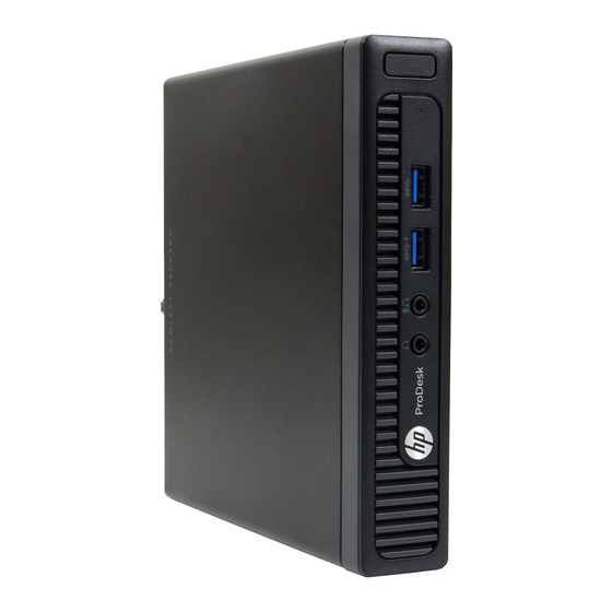
Front panel components (EliteDesk 800, EliteDesk 705, ProDesk 600) Dual-State Power Button USB 3.0 Port - Charging Hard Drive Activity Light Microphone/Headphone Connector USB 3.0 Port Headphone Connector NOTE: The USB 3.0 Port - Charging also provides current to charge a device such as a Smart Phone. The charging current is available whenever the power cord is plugged into the system, even when the system is off. -
Page 9: Front Panel Components (Prodesk 400)
Front panel components (ProDesk 400) Dual-State Power Button Microphone Connector Hard Drive Activity Light Headphone Connector USB 3.0 Ports NOTE: The Power On Light is normally white when the power is on. If it is flashing red, there is a problem with the computer and it is displaying a diagnostic code. -
Page 10: Rear Panel Components (Elitedesk 800)
Rear panel components (EliteDesk 800) DisplayPort Monitor Connectors USB 3.0 Ports (blue) VGA Monitor Connector RJ-45 Network Connector Line-Out Connector for powered audio devices Power Cord Connector (green) Chapter 1 Product features... -
Page 11: Rear Panel Components (Elitedesk 705)
Rear panel components (EliteDesk 705) DisplayPort Monitor Connectors USB 2.0 Ports (black) VGA Monitor Connector RJ-45 Network Connector Line-Out Connector for powered audio devices Power Cord Connector (green) USB 3.0 Ports (blue) Rear panel components (EliteDesk 705) -
Page 12: Rear Panel Components (Prodesk 600)
Rear panel components (ProDesk 600) DisplayPort Monitor Connectors USB 3.0 Ports (blue) VGA Monitor Connector RJ-45 Network Connector Line-Out Connector for powered audio devices Power Cord Connector (green) USB 2.0 Ports (black) Chapter 1 Product features... -
Page 13: Rear Panel Components (Prodesk 400)
Rear panel components (ProDesk 400) DisplayPort Monitor Connector USB 2.0 Ports (black) VGA Monitor Connector RJ-45 Network Connector USB 2.0 Ports with enhanced power (black) Power Cord Connector NOTE: The two upper USB ports have additional power capacity to support the Desktop Mini External Expansion Sleeves. NOTE: The two lower USB ports support wake-from-sleep states if that option is enabled in the Computer Setup (F10) utility. -
Page 14: Serial Number Location
Serial number location Each computer has a unique serial number and a product ID number that are located on the exterior of the computer. Keep these numbers available for use when contacting customer service for assistance. Chapter 1 Product features... -
Page 15: Hardware Upgrades
To reduce the risk of serious injury, read the Safety & Comfort Guide. It describes proper workstation, setup, posture, and health and work habits for computer users, and provides important electrical and mechanical safety information. This guide is located on the Web at http://www.hp.com/ergo. WARNING! Energized and moving parts inside. -
Page 16: Connecting The Power Cord
Connecting the power cord When connecting the power supply, it is important to follow the steps below to ensure the power cord does not pull free from the computer. Plug the female end of the power cord into the power supply brick (1). Connect the other end of the power cord to an electrical outlet (2). -
Page 17: Removing The Computer Access Panel
Removing the computer access panel To access internal components, you must remove the access panel: Remove/disengage any security devices that prohibit opening the computer. Remove all removable media, such as a USB flash drive, from the computer. Turn off the computer properly through the operating system, then turn off any external devices. Disconnect the power cord from the power outlet and disconnect any external devices. -
Page 18: Replacing The Computer Access Panel
Replacing the computer access panel Place the panel on the computer then slide it back (1) and tighten the thumbscrew (2) to secure the panel in place. Chapter 2 Hardware upgrades... -
Page 19: Changing From Desktop To Tower Configuration
Orient the computer so that its right side is facing up and place the computer in the optional stand. NOTE: To stabilize the computer in a tower orientation, HP recommends the use of the optional tower stand. Reconnect the power cord and any external devices, then turn on the computer. -
Page 20: Removing And Replacing A Hard Drive
Removing and replacing a hard drive NOTE: Before you remove the old hard drive, be sure to back up the data from the old hard drive so that you can transfer the data to the new hard drive. Remove/disengage any security devices that prohibit opening the computer. Remove all removable media, such as a USB flash drive, from the computer. - Page 21 Pull the release lever next to the rear of the hard drive outward (1). While pulling the release lever out, slide the drive back until it stops, then lift the drive up and out of the bay (2). To install a hard drive, you must transfer the silver and blue isolation mounting guide screws from the old hard drive to the new hard drive.
- Page 22 Align the guide screws with the slots on the chassis drive cage, press the hard drive down into the bay, then slide it forward until it stops and locks in place. Connect the hard drive power cable (1) and data cable (2) to the system board. Replace the access panel.
-
Page 23: Installing Additional Memory
Installing additional memory The computer comes with double data rate 3 synchronous dynamic random access memory (DDR3-SDRAM) small outline dual inline memory modules (SODIMMs). SODIMMs The memory sockets on the system board can be populated with up to two industry-standard SODIMMs. These memory sockets are populated with at least one preinstalled SODIMM. -
Page 24: Populating Sodimm Sockets
Populating SODIMM sockets There are two SODIMM sockets on the system board, with one socket per channel. The sockets are labeled DIMM1 and DIMM3. The DIMM1 socket operates in memory channel B. The DIMM3 socket operates in memory channel A. Item Description System Board Label... -
Page 25: Installing Sodimms
Installing SODIMMs CAUTION: You must disconnect the power cord and wait approximately 30 seconds for the power to drain before adding or removing memory modules. Regardless of the power-on state, voltage is always supplied to the memory modules as long as the computer is plugged into an active AC outlet. Adding or removing memory modules while voltage is present may cause irreparable damage to the memory modules or system board. - Page 26 Disconnect the hard drive power cable (1) and data cable (2) from the system board. WARNING! To reduce risk of personal injury from hot surfaces, allow the internal system components to cool before touching. Pull the release lever next to the rear of the hard drive outward (1). While pulling the release lever out, slide the drive back until it stops, then lift the drive up and out of the bay (2).
- Page 27 To remove a SODIMM, press outward on the two latches on each side of the SODIMM (1) then pull the SODIMM out of the socket (2). Slide the new SODIMM into the socket at approximately a 30° angle (1) then press the SODIMM down (2) so that the latches lock it in place.
-
Page 28: Replacing The Battery
The lithium battery is only used when the computer is NOT connected to AC power. HP encourages customers to recycle used electronic hardware, HP original print cartridges, and rechargeable batteries. For more information about recycling programs, go to http://www.hp.com/recycle. - Page 29 Locate the battery and battery holder on the system board. Depending on the type of battery holder on the system board, complete the following instructions to replace the battery. NOTE: You may need to use a small tool, such as tweezers or needle-nose pliers, to remove and replace the battery.
- Page 30 Pull back on the clip (1) and slide the replacement battery down into the holder (2). Type 2 Push the battery toward the outside of the chassis to release it from the holder and lift it out. Lower the battery so that is next to the holder then push it into the holder. Chapter 2 Hardware upgrades...
-
Page 31: Installing A Security Lock
NOTE: After the battery has been replaced, use the following steps to complete this procedure. Replace the computer access panel. Plug in the computer and turn on power to the computer. Reset the date and time, your passwords, and any special system setups using Computer Setup. Lock any security devices that were disengaged when the computer access panel was removed. -
Page 32: Appendix A Electrostatic Discharge
Use conductive field service tools. ● Use a portable field service kit with a folding static-dissipating work mat. If you do not have any of the suggested equipment for proper grounding, contact an HP authorized dealer, reseller, or service provider. NOTE: For more information on static electricity, contact an HP authorized dealer, reseller, or service provider. -
Page 33: Appendix B Computer Operating Guidelines, Routine Care And Shipping Preparation
Computer operating guidelines, routine care and shipping preparation Computer operating guidelines and routine care Follow these guidelines to properly set up and care for the computer and monitor: ● Keep the computer away from excessive moisture, direct sunlight, and extremes of heat and cold. ●... -
Page 34: Shipping Preparation
Shipping preparation Follow these suggestions when preparing to ship the computer: Back up the hard drive files to an external storage device. Be sure that the backup media is not exposed to electrical or magnetic impulses while stored or in transit. NOTE: The hard drive locks automatically when the system power is turned off. -
Page 35: Index
Index access panel memory removal 11 installation 17 replacement 12 socket population 18 specifications 17 battery replacement 22 power cord connection 10 product ID location 8 computer operating guidelines 27 rear panel components electrostatic discharge, preventing EliteDesk 705 5 damage 26 EliteDesk 800 4 ProDesk 400 7 ProDesk 600 6...