Table of Contents
Advertisement
Advertisement
Table of Contents

Related Manuals for Brady BradyPrinter i7100


Summary of Contents for Brady BradyPrinter i7100
- Page 1 USER MANUAL...
-
Page 2: Table Of Contents
Table of Contents Licenses ..............................4 EU Declaration of Conformity ............................4 1.2 FCC and Country-Specific Agency Approval Information ..................... 4 Technical Suppot & Repair ........................6 Application Engineering Services ......................7 Introduction ............................8 4.1 Instructions ................................... 8 4.2 Intended Use ................................8 4.3 Safety Instructions ................................ 9 4.4 Environment ................................. - Page 3 Disclaimer This manual is proprietary to Brady Worldwide, Inc. (hereafter "Brady"), and may be revised from time to time without notice. Brady disclaims any understanding to provide you with such revisions, if any. This manual is copyrighted with all rights reserved. No portion of this manual may be copied or reproduced by any means without the prior written consent of Brady. While every precaution has been taken in the preparation of this document, Brady assumes no liability to any party for any loss or damage caused by errors or omissions or by statements resulting from negligence, accident, or any other cause. Brady further assumes no liability arising out of the application or use of any product or system described, herein; nor any liability for incidental or consequential damages arising from the use of this document. Brady disclaims all warranties of merchantability of fitness for a particular purpose. Brady reserves the right to make changes without further notice to any product or system described herein to improve reliability, function, or design. Trademark Windows is a registered trademark of the Microsoft Corporation. BradyPrinter™ is a trademark of Brady Worldwide, Inc. All brand or product names referenced in this manual are trademarks (™) or registered trademarks (®) of their respective companies or organizations. ©2016 Brady Corporation. All rights reserved. Editor Regarding questions or comments please contact Brady Technical Support. Topicality Due to the constant further development of products discrepancies between documentation and product can occur. Please check BradyID.com for the latest update. Terms and conditions Deliveries and performances are effected under the General conditions of sale of BradyPrinter i7100. Brady Warranty Our products are sold with the understanding that the buyer will test them in actual use and determine for him or herself their adaptability to his/her intended uses. Brady warrants to the buyer that its products are free from defects in material and workmanship, but limits its obligation under this warranty to replacement of the product shown to Brady’s satisfaction to have been defective at the time Brady sold it. This warranty does not extend to any persons obtaining the product from the buyer. THIS WARRANTY IS IN LIEU OF ANY OTHER WARRANTY, EXPRESS OR IMPLIED, INCLUDING, BUT NOT LIMITED TO, ANY IMPLIED WARRANTY OF MERCHANTABILITY OR FITNESS FOR A PARTICULAR PURPOSE, AND OF ANY OTHER OBLIGATIONS OR LIABILITY ON BRADY’S PART. UNDER NO CIRCUMSTANCES WILL BRADY BE LIABLE FOR ANY LOSS, DAMAGE, EXPENSE OR CONSEQUENTIAL DAMAGES OF ANY KIND ARISING IN CONNECTION WITH THE USE, OR INABILITY TO USE, BRADY’S PRODUCTS. User Manual...
-
Page 4: Licenses
Licenses Reference to the EU Declaration of Conformity The printers of the Brady printer i7100 series comply with the relevant fundamental regulations of the EU Rules for Safety and Health: • Directive 2014/35/EU relating to electrical equipment designed for use within certain voltage limits • Directive 2014/30/EU relating to electromagnetic compatibility • Directive 2011/65/EU on the restriction of the use of certain hazardous substances in electrical and electronic equipment EU Declaration of Conformity www.bradyeurope.com/conformity FCC and Country-Specific Agency Approval Information NOTE : This equipment has been tested and found to comply with the limits for a Class A digital device, pursuant to Part 15 of the FCC Rules. These limits are designed to provide reasonable protection against harmful interference when the equipment is operated in a commercial environment. The equipment generates, uses, and can radiate radio frequency and, if not installed and used in accordance with the instruction manual, may cause harmful interference to radio communications. Operation of this equipment in a residential area is likely to cause harmful interference in which case the user may be required to correct the interference at his own expense. Changes or modifications not expressly approved by the party responsible for compliance could void the user’s authority to operate the equipment. This device complies with Part 15 of the FCC Rules. Operation is subject to the following two conditions: (1) This device may not cause harmful interference and, (2) this device must accept any interference received, including interference that may cause undesired operation. Prop 65 Warning Statement Prop 65 information related to this product is available at www.BradyID.com/i7100compliance. - Page 5 Turkey Turkish Ministry of Environment and Forestry (Directive on the Restriction of the use of certain hazardous substances in electrical and electronic equipment). Türkiye Cumhuriyeti: EEE Yönetmeliğine Uygundur China China RoHS Declaration information related to this product is available at www.BradyID.com/i7100compliance User Manual...
-
Page 6: Technical Suppot & Repair
Technical Support & Repair Technical Support & Repair In the event your i7100 Industrial Label Printer requires service or support, Brady offers comprehensive trouble- shooting support, set up assistance, how-to guidance and repair services globally. Brady offers both free-of- charge and fee-based levels of this support. Warranty coverage period, warranty benefits and availability of certain services may vary by Brady location. Consult your location for complete details. Technical Support: Troubleshooting and how-to guidance and special services via phone or web. Repair Services: Depot-based or on-site repair service depending on Brady location, for both in-warranty and out-of-warranty repair needs. Contacting Brady Technical Support The following chart shows the locations and contact information for Brady's global Technical support locations. Americas Canada 1-800-643-8766 bradycanada_technicalsupport@bradycorp.com United States 1-800-643-8766 tech_support@bradycorp.com Mexico 1-800-212-8181 soporte_tecnico@bradycorp.com Central America & Caribbean 1-866-748-4424 soporte_tecnico@bradycorp.com Brazil +55 11 4166-1500 ext 5 at@bradycorp.com... -
Page 7: Application Engineering Services
Application Engineering Services Application Engineering Services Brady offers fee-based application engineering services in some locations. If you need assistance with advanced integration of your i7100 Industrial Label Printer into a complex data flow scenario that is not supported under normal tech support capabilities, Brady's Application Engineering Team may be able to help. This team specializes in customized fee-based services that include: • Custom software programming • Custom front-end application software programming • Software template creation • Label file conversion • Scan-to-print mapping assistance • Advanced integration of printer & data flow Note: Application Engineering Services is not available in all Brady locations - contact the applications engineering email below or contact your local Brady Tech Support location for availability of these services in your area. Application Engineering Services Advanced integration and custom programming services to solve complex dataflow scenarios integrating printers, software, data collection devices and databases. Contacting Brady Application Engineering Contact Brady Application Engineering via email at application_engineering@bradycorp.com to discuss your application, or to learn about the availability of services in your location. User Manual... -
Page 8: Introduction
Introduction Instructions Important information and instructions in this documentation are designated as follows: Danger! Draws attention to an exceptionally great, imminent danger to your health or life due to hazardous voltages. Danger! Draws attention to danger with high risk which, if not avoided, may result in death or serious injury. Warning! Draws attention to danger with medium risk which, if not avoided, may result in death or serious injury. -
Page 9: Safety Instructions
Introduction Safety Instructions • The device is configured for voltages of 100 to 240 V AC. It only has to be plugged into a grounded socket. • Only connect the device to other devices which have a protective low voltage. • Switch off all affected devices (computer, printer, accessories) before connecting or disconnecting. • The device may only be used in a dry environment, do not expose it to moisture (sprays of water, mists, etc.). • Do not use the device in an explosive atmosphere. • Do not use the device close to high-voltage power lines. • If the device is operated with the cover open, ensure that people‘s clothing, hair, jewelry etc. do not come into contact with the exposed rotating parts. • The device or parts of it can become hot while printing. Do not touch during operation, and allow to cool down before changing material and before disassembly. • Risk of crushing when closing the cover. Touch the cover at the outside only. Do not reach into the swivel range of the cover. • Perform only those actions described in this operating manual. Work going beyond this may only be performed by trained personnel or service technicians. • Unauthorized interference with electronic modules or their software can cause malfunctions. • Other unauthorized work on or modifications to the device can also endanger operational safety. • Always have service work done in a qualified workshop, where the personnel have the technical knowledge and tools required to do the necessary work. • There are various warning stickers on the device. They draw your attention to dangers. Warning stickers must therefore not be removed, as then you and other people cannot be aware of dangers and may be injured. • The maximum sound pressure level is less than 70 dB(A). Danger! Danger to life and limb from power supply. -
Page 10: Installation
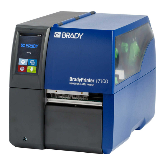
Installation Printer Overview 1 C over 2 Margin stop (center-justified) 3 Margin stop (outer) 4 Roll retainer 5 Ribbon supply hub 6 Ribbon take-up hub 7 Internal rewinder 8 Print unit 9 Cover (not on PEEL configurations) 10 Touchscreen display 11 LED "Power on" Figure 1 Overview 12 Ribbon deflection 13 P rinthead retainer with printhead 14 L abel sensor 15 A llen key 16 P rinthead locking lever 17 Print roller... - Page 11 Installation 23 Power switch 24 Power connection jack 25 Slot for SD card 26 2 USB master ports for keyboard, scanner, USB memory stick, Bluetooth adapter or service key 27 USB full-speed slave port 28 E thernet 10/100 Base-T 29 Serial RS-232 port 30 I/O interface (Option) 31 USB master port for keyboard, scanner, USB memory stick, Bluetooth adapter or service key Figure 3 Connections User Manual...
-
Page 12: Unpacking And Setting-Up The Printer
Installation Unpacking and Setting-up the Printer Lift the label printer out of the box. Check label printer for damage which may have occurred during transport. Set up printer on a level surface. Remove foam transportation safeguards near the printhead. Check delivery for completeness. Contents of delivery: • Label printer • Power cable • USB cable • Operator's Manual • CD with Windows driver and documentation Note! Please keep the original packaging in case the printer must be returned. Attention! The device and printing materials will be damaged by moisture and wetness. -
Page 13: Touchscreen Display
Touchscreen Display The user can control the operation of the printer with the control panel, for example: • Issuing, interrupting, continuing and canceling print jobs, • Setting printing parameters, e.g. heat level of the printhead, print speed, interface configuration, language and time of day ( Configuration Manual), • Control stand-alone operation with a memory module ( Configuration Manual), • Update the firmware ( Configuration Manual). Many functions and settings can also be controlled by software applications or by direct programming with a computer using the printer’s own commands. Programming Manual for details. Settings made on the touchscreen display make up the basic settings of the label printer. Note! It is advantageous, whenever possible, to make adaptations to various print jobs in the software. Start Screen After switching on During printing In pause state After print job Figure 4 Start screen The touchscreen display is operated directly by touch: •... - Page 14 Touchscreen Display With special software or hardware configurations additional symbols appear on the start screen: Printing on demand Printing on demand Direct cut without print job within print job with CU or PCU cutter installed Figure 5 Optional symbols on the start screen Release printing of a single label within a Release a direct cut without media feed print job including peeling-off, cutting... Figure 6 Optional symbols on the start screen In the headline several information are displayed as widgets depending on the configuration: Figure 7 Widgets in the start screen Displays the current data transfer in the form of a falling drop. The Save data stream function is active Configuration manual All received data are stored in a .lbl file. Warning ribbon end Configuration manual. The remaining diameter of the ribbon supply roll undershoots the set value. SD card installed USB memory installed gray: Bluetooth adapter installed, white: Bluetooth connection active WiFi connection active. The WiFi strength is displayed by the number of white arcs. Ethernet connection active USB connection active Clock time Table 2 Widgets in the start screen User Manual...
-
Page 15: Navigation In The Menu
Touchscreen Display Navigation in the Menu Start level Selection level Parameter/function level Figure 8 Menu levels To open the menu select on the start screen. Select a theme in the selection level. Several themes have substructures again with selection levels. To return from the current level to the upper one select . To leave the menu select Continue the selection until the parameter/function level is reached. Start a function. The will carry out the function possibly after a preparing dialogue. - or - Select a parameter to set. The setup possibilities are depending from the parameter type. Logical parameters Selection parameters Numerical parameters Date/time Figure 9 Samples for parameter setting Scroll bar for rough value setting Decreasing the value step-by-step Increasing the value step-by-step Return without saving the setting Return with saving the setting Parameter is disabled, touching enables the parameter Parameter is enabled, touching disables the parameter Figure 10 Buttons for parameter setting User Manual... -
Page 16: Loading Material
Loading Material Note! For adjustments and simple installation work, use the accompanying Allen key located in the top section of the print unit. No other tools are required for the work described here. Loading Media from Roll 7.1.1 Positioning the Media Roll on the Roll Retainer Allen Key (pull to remove) Figure 11... -
Page 17: Inserting The Media Strip Into The Printhead
Loading Material 7.1.2 Inserting the Media Strip into the Printhead Figure 12 Inserting the media strip into the printhead 1. Turn lever (2) counterclockwise to lift the printhead. 2. Adjust the guide(s) (6) with the knob (7) in such a way that the media can pass between the two guides. 3. Guide label strip over the internal rewinder to the print unit. 4. Guide label strip through the label sensor (5) in such a way that it exits the print unit between the printhead and the print roller. 5. Move guide(s) (6) against the edge(s) of the material by turning the knob (7). 7.1.3 Setting the Label Sensor The label sensor can be shifted perpendicular to the direction of paper flow for adaptation to the media. The sensor unit (1) of the label sensor is visible from the front through the print unit and is marked with an indentation in the label sensor retainer. When the printer is switched on, a yellow LED illuminates the sensor position. Loosen screw (4). Position label sensor with tab (5) in such a way that the sensor (1) can detect the label gap or a reflex or perfo- ration mark. - or, if the labels deviate from a rectangular shape, - Align label sensor using the tab (5) with the front edge of the label in the direction of paper flow. ... -
Page 18: Winding Up The Media Strip In Rewind Mode
Loading Material 7.1.4 Winding up the Media Strip in Rewind Mode Figure 13 Guiding the media strip in rewind mode In rewind mode, the labels are wound up internally after printing for later use. NOTE: a PEEL configuration printer, or standard printer upgraded with PEEL is required. 1. Install rewind guiding plate ( 7.4 on page 22). 2. Lift the pinch roller (4) off the rewind assist roller. 3. Guide label strip around the rewind guiding plate (2) to the internal rewinder (7). 4. Hold rewinder (7) firmly and turn knob (6) clockwise until it stops. 5. Push label strip under a bracket (5) of the rewinder and turn knob (6) counterclockwise until it stops. The rewinder is fully spread, thus gripping the label strip firmly. 6. Turn rewinder (7) counterclockwise to tighten the label strip. 7. -
Page 19: Removing The Wound Roll
Loading Material 7.1.5 Removing the Wound Roll Figure 14 Removing the wound roll 1. Turn lever (1) counterclockwise to lift the printhead. 2. Cut label strip and wind it fully around the rewinder (3). 3. Hold rewinder (3) firmly and turn knob (2) clockwise. The rewinder spindle relaxes and the wound roll (4) is released. 4. Remove wound roll (4) from rewinder (3). User Manual... -
Page 20: Winding Up The Liner In Peel-Off Mode
Loading Material 7.1.6 Winding up the Liner in Peel-Off mode Figure 15 Guidance of the material in peel-off mode In Peel-Off mode, the labels are removed after printing, and only the liner is wound up internally. NOTE: a PEEL configuration printer, or standard printer upgraded with PEEL is required. 1. Lift the pinch roller (5) off the rewind assist roller (3). 2. Remove labels from the first 100 mm of the liner. 3. Guide liner to the rewinder (8) around the dispense plate (2) and the rewind assist roller (3). 4. Hold rewinder (8) firmly and turn knob (7) clockwise until it stops. 5. Push liner under a bracket (6) of the rewinder (8) and align the outer edge of the strip to the media roll. 6. Turn knob (7) counterclockwise until it stops. The rewinder is fully spread, thus gripping the liner firmly. 7. Turn rewinder (8) counterclockwise to tighten the liner. 8. -
Page 21: Loading Fanfold Media
Loading Material Loading Fanfold Media Figure 16 Feed path of fanfold media 1. Turn ring (2) counterclockwise, so that the arrow points to the symbol , and thus release the margin stop (1). 2. Move the margin stop(s) (1) in such a position that the media can pass between the two margin stops. 3. Position media stack (4) behind the printer. Ensure that labels on the strip are visible from above. 4. Guide the media strip over the roll retainer (3) to the print unit. 5. Move the margin stop (1) against the media strip until chassis (5) and margin stop (1) or both margin stops touch the media strip without clamping or bending it. 6. Turn ring (2) clockwise, so that the arrow points to the symbol , and thus fix the margin stop (1) on the roll retainer (3). 7. Insert media strip into printhead ( 7.1.2 on page 17). 8. Set the label sensor ( 7.1.3 on page 17). 9. Set the head locking system ( 7.3 on page 22). 10. Turn lever (6) clockwise to lock the printhead. User Manual... -
Page 22: Setting The Head Locking System
Loading Material Setting the Head Locking System The printhead is pushed on via two plungers (1). In the basic setting the plungers are set in the middle of the printhead retainer. This setting can be used for the most applications. Figure 17 Setting the head locking system If the print density decreases in the outer areas when using very large media, the plungers can be displaced : Loosen threaded pins (3) at the plungers (1) with Allen key. Turn lever (2) clockwise to lock the printhead. Displace plungers to the scale value 70. Tighten the threaded pins (3). Removing and Installing the Rewind Guiding Plate, Dispense Plate or Tear-off Plate To convert the printer for use in another operating mode, a rewind guiding plate (2a), a dispense plate (2b) or a tear-off plate (2c) may need to be installed. Figure 18 Removing and installing the rewind guiding plate, dispense plate or tear-off plate Removing a plate Installing a plate ... -
Page 23: Loading Transfer Ribbon
Loading Material Loading Transfer Ribbon Note! The instructions below apply only when doing Thermal Transfer printing. For Direct Thermal printing, do not load a transfer ribbon; if one has already been loaded, remove it. Figure 19 Loading transfer ribbon 1. Clean printhead before loading the transfer ribbon ( 9.4 on page 26). 2. Turn lever (6) counterclockwise to lift the printhead. 3. -
Page 24: Setting The Feed Path Of The Transfer Ribbon
Loading Material Setting the Feed Path of the Transfer Ribbon Transfer ribbon wrinkling can lead to print image errors. The transfer ribbon deflection (3) can be adjusted so as to prevent wrinkles. Note! A maladjustment of the head locking system may also cause ribbon wrinkling ( 7.3 on page 22). Figure 21 Setting the feed path of the transfer ribbon Note! The adjustment is best carried out during printing. ... -
Page 25: Printing Operation
Printing Operation Attention! Printhead damage caused by improper handling! Do not touch the underside of the printhead with the fingers or sharp objects. Ensure that the labels are clean. Ensure that the label surfaces are smooth. Rough labels act like emery paper and reduce the service life of the printhead. -
Page 26: Cleaning
The printer can be damaged by aggressive cleansers. Do not use abrasive cleaners or solvents for cleaning the external surfaces or modules. Remove dust and paper fluff from the print area with a soft brush or vacuum cleaner. The cover of the printer can be cleaned with a standard cleanser. Approved Cleaning Swabs Use Brady part number PCK-6 cleaning swabs pre-soaked in print head cleaning solution. Package of 50 swabs. To be used to clean print head, sensor, rollers. Cleaning the Print Roller Accumulations of dirt on the print roller may impair the media transport and the print quality. Lift the printhead. -
Page 27: Cleaning The Label Sensor
Cleaning Cleaning the Label Sensor Attention! Label sensor can be damaged! Do not use sharp or hard objects or solvents to clean the label sensor. The label sensor can become dirtied with paper dust. This can adversely affect label detection. Figure 22 Cleaning the label sensor 1. Remove labels and transfer ribbon from the printer. 2. Loosen screw (2). 3. Hold pressed the button (1) and slowly pull label sensor outward via the tab (3). Ensure that the label sensor cable is not tensioned by this. 4. Clean label sensor the slots (4) with brush or cotton swab soaked in pure alcohol. 5. Push label sensor back via tab (3) and set it ( 7.1.3 on page 17). 6. Reload labels and transfer ribbon. User Manual... -
Page 28: Fault Correction
Fault Correction 10.1 Error Display The appearance of an error will be shown on the display: Figure 23 Error display The error treatment is pending on the error type 10.2 on page 28. The display offers the following possibilities to continue after an error occurred: The print job will be continued after clearing the error cause. Repeat The print job will be cancelled. Cancel The paper feed will be synchronized. Following the print job can be continued. Feed The error message will be ignored. The print job will be continued possibly with limited performance. Ignore The error does not allow print operation. Save log For detailed analysis several system files can be saved on an external memory. Table 3 Button in the error display 10.2 Error Messages and Fault Correction Error message Cause Remedy Invalid barcode content, e.g. alphanumeric Correct the barcode content. Barcode error characters in a numerical barcode The barcode is too big for the allocated area Reduce the size of the barcode or move it. - Page 29 Fault Correction Error message Cause Remedy No label found There are labels missing on the label Press Repeat repeatedly until printer recognizes the material next label on the material. The label format as set in the software Cancel current print job. does not correspond with the real label Change the label format set in the software. format Restart print job. Printer is loaded with continuous paper, but Cancel current print job. the software is set on labels Change the label format set in the software. Restart the print job. The size of the label is not defined in the Check programming. No label size programming. Out of paper Out of label roll Load labels. Error in the paper feed Check paper feed. Out of transfer ribbon Insert new transfer ribbon. Out of ribbon Cancel current print job.
-
Page 30: Problem Solution
Fault Correction 10.3 Problem Solution Problem Cause Remedy Transfer ribbon creases Transfer ribbon deflection not adjusted Adjust the transfer ribbon deflection. 7.5 on page 24 Head locking system not adjusted Adjust the head locking system. 7.3 on page 22 Transfer ribbon too wide Use a transfer ribbon slightly wider than the width of label. Print image has smears or Printhead is dirty Clean the printhead voids 9.4 on page 26 Temperature too high Decrease temperature via software. Unsuitable combination of labels and Use different type of ribbon. transfer ribbon Printer does not stop after Thermal printing is chosen in the software Change to thermal transfer printing. transfer ribbon runs out Printer prints a sequence Printer is in ASCII dump mode Cancel the ASCII dump mode. of characters instead of the label format Printer transports label Transfer ribbon incorrectly inserted. Check and, if necessary, correct the media, but transfer ribbon transfer ribbon web and the orientation does not move... -
Page 31: Media
Media 11.1 Media Dimensions Labels Continuous Material Figure 24 Media dimensions Dimension Designation Dimension (mm) Code Label width 4 -110 Label height 4 - 2000 in peel-off mode 12 - 200 Tear-off length > 30 Cut length with cutter > 5 with perforation cutter > 5 Perforation length > 2 Label distance >... -
Page 32: Printer Dimensions
& Reflective sensor Printhead Peel-off edge Tear-off edge Cut edge Figure 25 Device dimensions Dimension Designation Dimension (mm) Code Distance printhead - peel-off edge 13,5 Distance printhead - tear-off edge 13,5 Distance printhead - cut edge with cutter CU400 (Brady part #149069) 20,5 with perforation cutter PCU400 (Brady part #149078) 21,2 Distance 1st heating point - material edge Print width 105,6 Distance gap/reflective sensor - middle of paper track -55 - 0 i.e. permissible distance of reflex or cut-out marks from the middle of the material Distance gap/reflective sensor - 45,0 printhead Table 7 Device dimensions... -
Page 33: Reflex Mark Dimensions
Media 11.3 Reflex Mark Dimensions Labels with reflex marks Continuous Material with reflex marks virtual label front edge reflex mark Figure 26 Reflex mark dimensions Dimension Designation Dimension (mm) Code Label distance > 2 Distance between print zones > 2 Width of reflex mark > 5 Height of reflex mark 3 - 10 Distance mark - material edge 5 - 60 Distance mark - middle of paper track -55 - ±0 Distance virtual label front edge - actual label front edge 0 up to A / recomm. : 0... -
Page 34: Cut-Out Mark (Notch) Dimensions
Media 11.4 Cut out Mark (notch) Dimensions Labels with cut-out marks (notches) Continuous Material with cut-out marks (notches) for marginal cut-out marks minimum liner thickness 0,06 mm Figure 27 Cut-out mark dimensions Dimension Designation Dimension (mm) Code Label distance > 2 Distance between print zones > 2 Width of cut-out mark > 5 for marginal cut-out > 8 Height of cut-out mark 2 - 10 Distance mark - material edge 5 - 60 Distance mark - middle of paper track -53 - ±0 Sensor recognized virtual label front edge with gap sensor recognition Rear edge cut-out... -
Page 35: Index
Index Application Engineering Services ..7 Important information......8 Reflex marks........33 Intended use ........8 Rewind guide plate ......22 Rewind mode........18 Cleaning information ........26 printhead ........26 Label sensor cleaning.......27 Safety instructions ......9 print roller ........26 Lithium battery ........9 Service work ........9 swabs ..........26 Loading fanfold labels.......21 Setting-up .........12 Cleaning information......26 Loading media ........16 Supply voltage ........12 Connecting ........12 Loading media from roll ....16 Switching on ........12 Contents of delivery ......12 Loading transfer ribbon.....23 Synchronization of the paper feed ..25... - Page 36 Belgium Latin America ........1-414-540-5560 www.bradycorp.com/global Malaysia ..........60-4-646-2700 Tel: +32 (0) 52 45 78 11 Mexico ............525-399-6963 New Zealand ........61-2-8717-2200 Brady Corporation Asia Philippines ..........63-2-658-2077 1 Kaki Bukit Crescent Singapore ..........65-6477-7261 Singapore 416236 Taiwan ..........886-3-327-7788 www.bradycorp.com/global Thailand ..........66-2-793-9200 Tel: 65-6477-7261 Y4418000 i7100 User Manual (Printed-English): Brady Part No. 149058 User Manual...