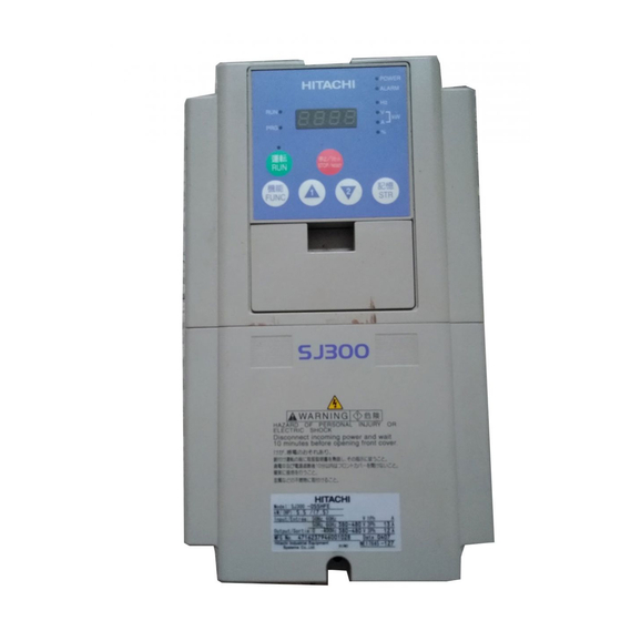
Hitachi SJ300 Series Manual
Sensorless vector contro
Hide thumbs
Also See for SJ300 Series:
- Instruction manual (295 pages) ,
- Quick reference manual (43 pages) ,
- Replacement manual (23 pages)
Table of Contents
Advertisement
Quick Links
Advertisement
Table of Contents

Related Manuals for Hitachi SJ300 Series


Summary of Contents for Hitachi SJ300 Series
- Page 1 VARIABLE FREQUENCY DRIVE Sensorless Vector Control...
- Page 3 VERSATILE FUNCTIONS ENCOMPASS MORE APPLICATIONS VERSATILE FUNCTIONS ENCOMPASS MORE APPLICATIONS Enhanced input/output function Deceleration and stop at ■ ■ power failure Intelligent terminal system is utilized on all input and output terminals. SJ300 decelerates and stops the motor using regenera- Sink/source type logic is user-selectable.
- Page 4 (It does not comply with European EMC directive. To meet the EMC directive, Standard enclosure protection for SJ300 is IP20 (NEMA1*). please use an EMI filter.) For IP54 (NEMA12), please contact Hitachi sales office. Up to 22kW. An Optional conduit box is required for 30kW to 55kW to meet NEMA1. J300 series...
- Page 5 The protection method conforms to JEM 1030 / NEMA (U.S.). braking torque is required. The applicable motor refers to Hitachi standard 3-phase motor (4-pole). Storage temperature refers to the temperature in transportation. Conforms to the test method specified in JIS C0040(1999).
- Page 6 The protection method conforms to JEM 1030 / NEMA (U.S.). braking torque is required. The applicable motor refers to Hitachi standard 3-phase motor (4-pole). Storage temperature refers to the temperature in transportation. To use other motors, be sure to prevent the rated motor current (50Hz) from exceeding the rated output current of the inverter.
- Page 7 The protection method conforms to JEM 1030 / NEMA (U.S.). Braking resistor is not integrated in the inverter. Please an optional dynamic braking unit when large braking torque is required. The applicable motor refers to Hitachi standard 3-phase motor (4-pole). Storage temperature refers to the temperature in transportation.
- Page 8 DIMENSIONS SJ300-004LFU, 007 - 055LFU/ HFE, HFU [Unit:mm (inch)] 150(5.91) Inches for reference only 130(5.12) Digital Operator 80(3.15) Exhaust 25(0.98) 2 - 6 ( 0.24) Wall 6(0.24) 3- 20 ( 0.78 ) 130(5.12) Wiring Hole Air intake LFU, HFU type. ( 055LFU, HFU ) 75 ( 2.95 ) Conduit box to meet NEMA1 rating 143(5.63)
- Page 9 SJ300-150 - 220LFU/ HFE, HFU [Unit:mm (inch)] Inches for reference only Digital Operator 250 ( 9.84 ) 229 ( 9.02 ) 2- 7 ( 0.28 ) Exhaust 80 ( 3.15 ) 24.5 ( 0.97 ) Wall 7 ( 0.28 ) 229 ( 9.02 ) Air intake LFU, HFU type.
- Page 10 SJ300-370 - 450LFU, 370 - 550HFE, HFU [Unit:mm (inch)] Digital Operator Inches for reference only 80 ( 3.15 ) Exhaust 32.5 ( 1.28 ) 2- 12( 0.47) Wall 2-12 (0.47) Air intake 300 (11.81) 390 (15.35) 90(3.54) Conduit box to meet NEMA1 rating ( Optional ) SJ300-550LFU [Unit:mm (inch)] Digital Operator...
- Page 11 SJ300-750, 900HFE, HFU SJ300-1100HFE, HFU 1320HFE 1500HFU Digital Operator Digital Operator 62.5 ( 2.46 ) 80 ( 3.15 ) 80 ( 3.15 ) 32.5 ( 1.28 ) 12(0.47 ) 2- 12( 0.47) Exhaust Exhaust Wall Wall 2-12 (0.47) Air intake 2 - 12 ( 0.47 ) 380 (14.76)
- Page 12 OPERATION and PROGRAMMING SJ300 Series can be easily operated with the digital operator ( OPE-S ) provided as standard. The digital operator can also be detached and can be used for remote-control. Multilingual ( English, French, German, Italian , Spanish and Portuguese) operator with copy function ( SRW-0EX ) and digital operator with potentiometer ( OPE-SR ) are also available as options.
- Page 13 FUNCTION LIST = Allowed ⃝ ●MONITORING FUNCTIONS and MAIN P ROFILE PARAMETERS = Not permitted × Default Setting Run-time Run-time Data Edit Code Name Description Setting (Enabled at b031) -FE(CE) -FU(UL) Output frequency monitor 0.00 - 99.99/100.0 - 400.0Hz d001 0.0 - 999.9A d002 Output current monitor...
- Page 14 = Allowed ⃝ = Not permitted × Default Setting Run-time Run-time Data Edit Code Name Description Setting (Enabled at b031) -FE(CE) -FU(UL) A041 Torque boost method selection 00(Manual torque boost) / 01(Automatic torque boost) × × A241 Torque boost method selection for second motor 00(Manual torque boost) / 01(Automatic torque boost) ×...
- Page 15 = Allowed ⃝ ●B GROUP: FINE TUNING FUNCTIONS = Not permitted × Default Setting Run-time Run-time Data Edit Code Name Description Setting (Enabled at b031) -FE(CE) -FU(UL) 00(Alarm output after trip, automatic restart disable) / 01(Restart at 0Hz) / 02(Re- b001 Selection of automatic restart mode sume operation after frequency matching)/ 03(Resume previous frequency after...
- Page 16 = Allowed ⃝ = Not permitted × Default Setting Run-time Run-time Data Edit Code Name Description Setting (Enabled at b031) -FE(CE) -FU(UL) b100 Free-setting V/f frequency (1) 0.0 - Free-setting V/f frequency (2) × × Free-setting V/f voltage (1) 0.0 - 800.0V ×...
- Page 17 Auto-tuning setting 00(NOR:Disable) / 01(NOR:No rotation) / 02(AUT:Rotation) × × H002 Motor data selection for first motor 00(Hitachi standard motor) / 01(Auto-data) / 02(Adaptive-data) × × H202 Motor data selection for second motor 00(Hitachi standard motor) / 01(Auto-data) / 02(Adaptive-data) ×...
- Page 18 = Allowed ⃝ = Not permitted × Default Setting Run-time Run-time Data Edit Code Name Description Setting (Enabled at b031) -FE(CE) -FU(UL) H023 Motor constant I setting for first motor 0.00 - 9.99/100.00 - 655.3 × × H223 0.00 - 9.99/100.00 - 655.3 Motor constant I setting for second motor ×...
- Page 19 TERMINALS MAIN CIRCUIT TERMINALS ●Terminal Description Terminal Symbol Terminal Name R ( L1 ) , S ( L2 ) , T ( L3 ) Main power supply input terminals U ( T1 ) , V ( T2 ) , W ( T3 ) Inverter output terminals PD ( +1 ) , P ( + ) DC reactor connection terminals...
- Page 20 ●Terminal Description [ ]: Default setting (CE/UL) Symbol Name Explanation of Terminals Ratings Common Terminal for Analog Common terminal for H, O, O2, OI, AM, and AMI. Do not ground. ― Power Source Power Supply Power Source for Frequency Power supply for frequency command input DC 10V, 20mA max.
- Page 21 PROTECTIVE FUNCTIONS Display Display on remote operator/copy unit on digital Name Cause(s) operator ERR1**** OC.Drive While at constant speed The inverter output was short-circuited, or the During deceleration OC.Decel motor shaft is locked or has a heavy load. These Over-current conditions cause excessive current for the invert- protection OC.Accel...
- Page 22 CONNECTING DIAGRAM ■Source type logic In case of 400V class, place a transformer for operating circuit to receive 200V. 200V - 240V±10% 50/60Hz±5% (T1) U SJ300 R(L1) (T2) V S(L2) (T3) W (+1) PD T(L3) DC link choke (*2)Remove connection with J51 (*2)...
- Page 23 ■Sink type logic In case of 400V class, place a transformer for operating circuit to receive 200V. 200V - 240V±10% 50/60Hz±5% (T1) U SJ300 R(L1) (T2) V S(L2) (T3) W (+1) PD T(L3) DC link choke (*2)Remove connection with J51 (*2)...
- Page 24 1. USING INTERNAL POWER SUPPLY OF THE INVERTER ( 1 ) Sink type logic ( 2 ) Source type logic DC24V DC24V SJ300 Hitachi EH-150 series PLC Hitachi EH-150 series PLC SJ300 Output Module Output Module (Note: Place short-circuit bar...
- Page 25 WIRING and ACCESSORIES Power Supply Wiring Motor Output Fuse Input Power Lines Model (Class J) Voltage (kW(HP)) Signal Lines 0.4(1/2) SJ300-004LFU 0.7(1) SJ300-007LFU 1.5(2) SJ300-015LFU 2.2(3) SJ300-022LFU 3.7(5) SJ300-037LFU Fuse 5.5(7.5) SJ300-055LFU 7.5(10) SJ300-075LFU 13.3 0.75mm shielded 200V 11(15) SJ300-110LFU 21.2 wire 15(20)
- Page 26 ACCESSORIES ■OPERATOR, CABLE ●OPERATOR Model Potentiometer Remote Control Installation in SJ300 Copy Function Multilingual ⃝ ( Standard for SJ300 ) ⃝ OPE-S ⃝ ( OPE-SRE: Standard for SJ300 UL version ) ⃝ ⃝ OPE-SR/SRE ⃝ ⃝ ⃝ ⃝ SRW-0EX OPE-SRE: English overlay ●CABLE FOR OPERATOR ■Multilingual Operator with Copy Function...
- Page 27 ■EXPANSION CARD Up to two expansion cards can be installed inside the SJ300. Digital Input Expansion Card SJ-DG Output frequency, acceleration time, deceleration time, torque limit, and orientation position * can be set by a digital output device such as PLC, etc. ( Binary or BCD ) ●Connecting Diagram ●Data Bit Configuration Data input error...
- Page 28 Expensive hard-wiring can be eliminated for space saving and cost reduction, and installation/ replacement within the system can be easily done. ●Specifications Applicable DeviceNet specification Volume 1-Relesse 2.0 Volume 2-Relesse 2.0 Vendor name Hitachi, Ltd. Vendor ID=74 General data Device profile name Slave DC Drive Profile No.=13...
- Page 29 NET-A input connection Manufacturer Model Code NET-B NET-B input connection Phoenix Contact MC 1.5/3-ST-3.81 Note: Network function must be supported by the software of the inverter used with SJ-DN, SJ-PBT, or SJ-LW. For the detail, please contact Hitachi sales office.
- Page 30 ■ACCESSORIES MATRIX FOR SJ300 SERIES Radio noise filter Capacity DC reactor Input side AC reactor EMI filter Ferrite core Radio noise filter (Capacitor filter) Model name (see page 31) (see page 32) (see page 33) (see page 33) (see page 35)
- Page 31 DC Reactor ( For harmonics suppression ) DCL- □ □□ ●Model Name Configuration ●Connecting Diagram Inverter DCL-L-0.2 DC reactor (+)P Applicable inverter capacity (kW) Voltage L : 200V class H: 400V class (+1)PD ●Dimensional drawings Bmax Amax 2- K Caution label X + 1 <Figure 1>...
- Page 32 Input Side AC Reactor ( For harmonics suppression, power factor improvement ) ALI - □□□ ●Dimensional drawings <Figure 1> ●Model Name Configuration ALI-2.5L2 Version L : 3-phase 200V class H: 3-phase 400V class Inverter output capacity Input side ●Connecting Diagram AC reactor Inverter Motor...
- Page 33 EMI Filter NF-CEH □□ ●Model Name Configuration ●NF-CEH7-CEH10 [unit:mm] NF-CE-H 7 74±3 56±2 Noise filter rated current Power supply H: 200/400V For European EMC compliance Series name Applicable inverter capacity Weight Rated Model name current (kg) 400V class 200V class NF-CEH7 Up to 2.2kW 0.4, 0.75kW...
- Page 34 ●Ferrite core ●Ferrite core 1 1 5 + 2 R2.6 L10 95 + 1 FC-H300 ZCL-B75 [unit:mm] [unit:mm] 66 + 2 161 MAX 140±0.5 R3.5±0.3 7±0.5 ● To meet European EMC class A limits Applicable inverter capacity Required ferrite Model Name 200V class 400V class Core...
- Page 35 Radio Noise Filter ( Zero-phase Reactor ) ZCL-A, ZCL-B40 ●Dimensional Drawings [Unit:mm] [ZCL-B40] [ZCL-A] Opening for wiring Mounting hole 3 - M 4 Opening for wiring max. 95 max. 80 ± 0.5 2 - φ5. 5 ●Connecting Diagram ZCL-□□□ Motor Power Inverter Supply...
- Page 36 Dynamic Braking Unit BRD- □□□ □□□ ●Specifications 200V class 400V class Specifications BRD-S3 BRD-E3 BRD-E2-30K BRD-E2-55K BRD-EZ3 BRD-EZ2-30K BRD-EZ2-55K BRD-EZ3-110K 4Ω or more 2Ω or more 10Ω or more 6Ω or more 3Ω or more Short period ( *1) ー ー...
- Page 37 Braking Resistor ( Rear-mounted type ) □ □□□ □ [ Unit: mm ] (2) (2) [Figure 2] [Figure 1] Allowable braking Instantaneous Allowable continuous Applicable inverter Resistance value Rated capacity Overheat protection Model name Figure Weight(kg) capacity cycle ( %ED ) ON period 004-055LF□...
- Page 38 Braking Resistor ( Standard type ) SRB- □□□ ●Dimensional Drawings [Unit: mm] Note 1: The internal themal contact capacity is 250V ●Connecting Diagram ●Circuit Diagram AC, 2A max. It is on under nomal condition (NC contact). Dynamic Prevents abnormal heat resulting from the Inverter braking unit Braking resistor...
- Page 39 LCR Filter The LCR filter smoothes inverter output current and voltage waveforms and reduces vibrations in the motor, noise from the motor, and radiated noise from the wires. The LCR filter suppresses a voltage surge that occurs at the motor terminals when driving a 400V class motor. Combination of L, C, and R [200V class] Motor capacity ( kW/HP )
- Page 40 Output Side AC Reactor ( For reducing vibration in the motor ) ACL- □ □□□ Model Name Configuration Connecting Diagram ACL-L2-0.4 Reactor Inverter Motor (L1) (T1) Motor capacity Power ( In case of kW, 4P ) (L2) (T2) Supply Version (L3)...
- Page 41 Analog Operator Panel OPE-4MJ2, OPE-8MJ2 Standard Specifications Internal Circuit Diagram Model OPE-4MJ2 OPE-8MJ2 Meter size 43mm square 80mm square 0-50/60/100/120Hz 0-50/60/100/120/200/240Hz Meter indication Frequency setting device 0.2W, 2kΩ FWD/STOP DC20mV-28V, 0.1mA-0.1A Switch REV/STOP Weight (kg) 0.43 Ambient temperature and humidity -10-50 ℃...
- Page 42 FOR COMPACT PANEL Heat accumulation in the panel can be reduced by arranging inverter heat sink outside. SJ300 - 004 – 055LFU SJ300 - 075, 110LFU, HFU/E SJ300 - 150 – 220LFU, HFU/E SJ300 - 300LFU, HFU/E - 007 – 055HFU/E Exhaust Exhaust Exhaust...
- Page 43 1.5kw 4-pole totally enclosed type motor (Base frequency of 60 Hz) (Note: Torque characteristics may vary according to the model.) DERATING DATA The SJ300 series can be used at ambient temperature of -10˚C to 50˚C. However, when using at 50˚C, derating is required. ( 200V class )
- Page 44 A max. 400Hz can be selected on the SJ300 Series. However, a two-pole motor can attain up to approx. 24,000 rpm, which is extremely dangerous.
- Page 45 When an electromagnetic contactor is installed between the inverter and the motor, do not perform on-off switching during contactor running operation. When used with standard applicable output motors (standard three-phase squirrel-cage four-pole motors), the SJ300 Series Wiring does not need a thermal relay for motor protection due to the internal electronic protective circuit. A thermal relay, however,...
- Page 46 MEMO...
- Page 47 Printed in Japan ( H ) SM-E231U 1006...