Hitachi SJ300 Series Instruction Manual
Hitachi instruction manual inverter sj300 series
Hide thumbs
Also See for SJ300 Series:
- Manual (48 pages) ,
- Quick reference manual (43 pages) ,
- Replacement manual (23 pages)
Table of Contents
Advertisement
Quick Links
Advertisement
Table of Contents
Troubleshooting

Related Manuals for Hitachi SJ300 Series


Summary of Contents for Hitachi SJ300 Series
- Page 1 SJ300 Series Inverter Instruction Manual • Three-phase Input • Three-phase Input U.S. Version Models Manual Number: NB613XJ September 2006 Hitachi Industrial Equipment Systems Co., Ltd. 200V Class 400V Class European Version Models After reading this manual, keep it handy for future reference.
-
Page 3: Safety Messages
Safety Messages For the best results with the SJ300 Series inverter, carefully read this manual and all of the warning labels attached to the inverter before installing and operating it, and follow the instruc- tions exactly. Keep this manual handy for quick reference. - Page 4 Co., Ltd. CAUTION: Be sure to connect a motor thermal disconnect switch or overload device to the SJ300 series controller to assure that the inverter will shut down in the event of an overload or an overheated motor. HIGH VOLTAGE: Dangerous voltage exists until power light is OFF. Wait at least 5 minutes after input power is disconnected before performing maintenance.
- Page 5 SJ300 Inverter CAUTION: a) Motor must be connected to protective ground via low resistive path (< 0.1Ω) b) Any motor used must be of a suitable rating. c) Motors may have hazardous moving parts. In this event suitable protection must be provided. CAUTION: Alarm connection may contain hazardous live voltage even when inverter is disconnected.
- Page 6 Index to Warnings and Cautions in This Manual Installation—Cautions for Mounting Procedures CAUTION: Be sure to install the unit on flame-resistant material such as a steel plate. Otherwise, there is the danger of fire. CAUTION: Be sure not to place any flammable materials near the inverter. Otherwise, there is the danger of fire.
- Page 7 Otherwise, there is the possibility of damage to the inverter and the danger of fire. CAUTION: Be sure not to connect an AC power supply to the output termi- nals. Otherwise, there is the possibility of damage to the inverter and the danger of injury and/or fire.
- Page 8 CAUTION: Be sure to install a fuse in each phase of the main power supply to the inverter. Otherwise, there is the danger of fire.
- Page 9 (be sure to design the machine so that safety for personnel is secure even if it restarts.) Otherwise, it may cause injury to personnel. WARNING: If the power supply is cut OFF for a short period of time, the inverter may restart operation after the power supply recovers if the Run command is active.
- Page 10 viii Cautions for Operations and Monitoring CAUTION: The heat sink fins will have a high temperature. Be careful not to touch them. Otherwise, there is the danger of getting burned. CAUTION: The operation of the inverter can be easily changed from low speed to high speed.
-
Page 11: General Warnings And Cautions
If an optional remote operator is used and the retry function has been selected, this will also allow automatic restarting when a Run command is active. - Page 12 CAUTION: Do not insert leading power factor capacitors or surge absorbers between the output terminals of the inverter and motor. Power Input L1, L2, L3 CAUTION: Be sure to connect the grounding terminal to earth ground. CAUTION: When inspecting the unit, be sure to wait five minutes after tuning OFF the power supply before opening the cover.
- Page 13 1. The unbalance factor of the power supply is 3% or higher. 2. The power supply capacity is at least 10 times greater than the inverter capacity (or the power supply capacity is 500 kVA or more).
-
Page 14: Sj300-004Lfu
® Cautions, Warnings, and Instructions Wiring Warnings The Cautions, Warnings, and instructions in this section summarize the procedures necessary to ensure an inverter installation complies with Underwriters Laboratories for Electrical Practices and Wire Sizes WARNING: “Use 60/75°C Cu wire only” or equivalent. WARNING: “Open Type Equipment.”... -
Page 15: Table Of Contents
Motor Input 400V Output Voltage Inverter Model 0.75 SJ300-007HFU/E SJ300-015HFU/E SJ300-022HFU/E SJ300-040HFU/E SJ300-055HFU/E SJ300-075HFU/E SJ300-110HFU/E SJ300-150HFU/E 18.5 SJ300-185HFU/E 400V SJ300-220HFU/E SJ300-300HFU/E SJ300-370HFU/E SJ300-450HFU/E SJ300-550HFU/E SJ300-750HFU/E SJ300-900HFU/E SJ300-110HFU/E SJ300-1320HFE SJ300-1500HFU SJ300 Inverter Torque Wire Size Range (AWG) ft-lbs (N-m) 1 AWG (75°C) 1/0 || 1/0 AWG 3/0 (1/0 || 1/0 AWG) 3/0 (1/0 || 1/0 AWG) -
Page 16: Table Of Contents
The connector must be fixed using the crimping tool specified by the connector manufacturer. Motor Overload Hitachi SJ300 inverters provide solid state motor overload protection, which depends on the proper setting of the following parameters: Protection • B012 “electronic overload protection”... -
Page 17: Table Of Contents
Table of Contents Safety Messages Hazardous High Voltage General Precautions - Read These First! Index to Warnings and Cautions in This Manual General Warnings and Cautions UL® Cautions, Warnings, and Instructions Table of Contents Revisions Contact Information Chapter 1: Getting Started Introduction SJ300 Inverter Specifications Introduction to Variable-Frequency Drives... -
Page 18: Table Of Contents
Appendix B: Serial Communications Introduction Communications Protocol Communications Reference Information Appendix C: Drive Parameter Settings Tables Introduction Parameter Settings for Keypad Entry Appendix D: CE–EMC Installation Guidelines CE–EMC Installation Guidelines Hitachi EMC Recommendations Index 5–2 5–3 5–6 6–2 6–5 6–9 6–10 6–18... -
Page 19: Sj300-900Hfu/E 3/0 (1/0 || 1/0 Awg) 10.1
Add programming error codes, pages 3–67, 3–68 Update keypad navigation map, pages 2–25, 3–4 Add Appendix D: CE-EMC Installation Guidelines Moved Hitachi EMC Recommendations from page iv to D–4 Contents, Revisions, Index updates Front cover update Added default terminal symbols to tables on 3–47, 3–53... -
Page 20: Contact Information
Phone: +852-2735-9218 Fax: +852-2735-6793 NOTE: To receive technical support for the Hitachi inverter you purchased, contact the Hitachi inverter dealer from whom you purchased the unit, or the sales office or factory contact listed above. Please be prepared to provide the following inverter nameplate information: 1. -
Page 21: Introduction
Getting Started In This Chapter... — Introduction — SJ300 Inverter Specifications — Introduction to Variable-Frequency — Frequently Asked Drives... Questions... page... - Page 22 • Models from 0.4–11kW (1/2 to 15hp) have built- in dynamic braking units • Cooling fan has ON/OFF selection to provide longer life A full line of accessories from Hitachi is avail- able to complete your motor control application. These include: • Digital remote operator keypad •...
- Page 23 Digital Operator The SJ300 Series inverters have a detachable keypad (called a digital operator) on the front panel of the housing. The particular keypad that comes with the inverter depends on the country Interface or continent corresponding to the particular model number. The standard digital operators Components occupy just part of the keypad recess in the panel.
- Page 24 1–4 Introduction Removable The SJ300 Series inverters are designed for long life and ease of service. Several components are removable as shown below, aiding installation or parts replacement. Details on how and Components when to remove these parts are in the referenced chapters.
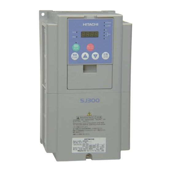
- Page 25 Specifications The Hitachi SJ300 inverters have product specifi- cations labels located on the front and the right Label and Agency side of the housing, as pictured to the right. Be Approvals sure to verify that the specifications on the labels match your power source, motor, and application safety requirements.
-
Page 26: Sj300 Inverter Specifications
1–6 SJ300 Inverter Specifications SJ300 Inverter Specifications Tables for 200V Note that class inverters footnotes for all specifications tables. The 200V models in the upper table below (1/2 to 15 hp) include internal dynamic braking units (see Item SJ300, 200V models, U.S. version Applicable motor size, 4-pole *2 Rated capacity (200/240V) kVA Rated input voltage... - Page 27 Tables for 400V Note that “General Specifications” on page 1–9 footnotes for all specifications tables. The 400V models in the upper table below (1 to 15 hp) class inverters include internal dynamic braking units (see Item SJ300 inverters, U.S. version 400V models European ver.
- Page 28 Note 5: When SLV is selected, please set the carrier frequency higher than 2.1 kHz. Note 6: At the rated voltage when using a Hitachi standard 3-phase, 4-pole motor (when Note 7: The braking torque via capacitive feedback is the average deceleration torque at the Note 8: The frequency command will equal the maximum frequency at 9.8V for input voltage...
-
Page 29: Specifications
General The following table (continued on next page) applies to all SJ300 inverter models. Specifications Item Protective enclosure *1, *11 Control method Output frequency range *4 Frequency accuracy Frequency setting resolution Volt./Freq. characteristic *5 Speed fluctuation Overload capacity (output current) Acceleration/deceleration time Input Freq. - Page 30 1–10 SJ300 Inverter Specifications Item Other user-settable parameters Carrier frequency range Protective functions Environ- Temperature (*9) ment Humidity Vibration *10 Location Coating color Accessories Feedback PCB Digital input PCB Others Operator input devices Signal Ratings Detailed ratings are in Signal / Contact Built-in power for inputs Intelligent (programmable) logic inputs Intelligent (programmable) logic outputs Open collector type, 50mA max.
- Page 31 Derating Curves The maximum available inverter current output is limited by the carrier frequency and ambient temperature. The carrier frequency is the inverter’s internal power switching frequency, settable from 0.5 kHz to 12 kHz. Choosing a higher carrier frequency tends to decrease audible noise, but it also increases the internal heating of the inverter, thus decreasing (derating) the maximum current output capability.
- Page 32 1–12 SJ300 Inverter Specifications Derating curves, continued... SJ300 30 to 55 kW at 50 deg. C ambient, continued 100% Carrier Frequency (kHz) SJ300 75 to 150 kW at 50 deg. C ambient 100% Carrier Frequency (kHz) 015 to 185H 370H 450H 220H 300H...
-
Page 33: Introduction To Variable-Frequency Drives
Introduction to Variable-Frequency Drives The Purpose of Hitachi inverters provide accurate speed control for 3-phase AC induction motors. You connect Motor Speed AC power to the inverter, and connect the inverter to the motor. Many applications can benefit from the use of variable-speed drives in several ways:... - Page 34 The Hitachi inverter is a rugged and reliable device. The intention is for the inverter to assume the role of controlling power to the motor during all normal operations. Therefore, this manual instructs you not to switch OFF power to the inverter while the motor is running (unless it is an emergency stop).
- Page 35 (see Braking” on page 5–6 for extended periods of time, the SJ300 may not be suitable (contact your Hitachi distributor). The inverter parameters include acceleration and deceleration, which you can set to match the needs of the application.
- Page 36 1–16 Introduction to Variable-Frequency Drives Acceleration and deceleration settings specify the time required to go from a stop to maximum frequency (or visa versa). The resulting slope (speed change divided by time) is the acceleration or deceleration. An increase in output frequency uses the accel- eration slope, while a decrease uses the deceleration slope.
-
Page 37: Frequently Asked Questions
Frequently Asked Questions What is the main advantage in using an inverter to drive a motor, compared to alternative solutions? A. An inverter can vary the motor speed with very little energy loss, unlike mechanical or hydraulic speed control solutions. The resulting energy savings can often pay for the inverter in a relatively short time. - Page 38 NOTE: There may be other factors that will affect motor selection, including heat dissipation, motor operating speed profile, enclosure type, and cooling method. A. Hitachi inverters can be configured to operate motors with 2, 4, 6, or 8 poles. The A. Yes. Models SJ300-004XXX through SJ300-110XXX have built-in dynamic braking A.
- Page 39 Inverter Mounting and Installation In This Chapter... — Orientation to Inverter Features — Basic System Description — Step-by-Step Basic Installation — Powerup Test — Using the Front Panel Keypad page...
-
Page 40: Orientation To Inverter Features
3. Inspect the specifications label on the front or side of the inverter. Make sure it matches the product part number you ordered. Main Physical The SJ300 Series inverters vary in size according to the current output rating and motor size for Features each model number. All feature the same basic keypad and connector interface for consistent ease of use. - Page 41 2. Second-level access - First, ensure no power source of any kind is connected to the inverter. If power has been connected, wait five minutes after powerdown and verify the Charge Lamp indicator is OFF to proceed. Then locate the recessed retention screw at the bottom of the main front panel.
- Page 42 2–4 Orientation to Inverter Features 3. Third-level access - The SJ300 provides for field installation of interface circuits. These circuits are on expansion cards, to be installed in the expansion bay. To access the expansion bay, you will need to remove the upper front panel.
-
Page 43: Basic System Description
Input side This is useful in suppressing harmonics induced AC Reactor on the power supply lines, or when the main power voltage imbalance exceeds 3% (and power source capacity is more than 500 kVA), or to smooth out line fluctuations. It also improves the power factor. -
Page 44: Step-By-Step Basic Installation
2–6 Step-by-Step Basic Installation Step-by-Step Basic Installation This section will guide you through the following basic steps of installation: 1. Study the warnings associated with mounting the inverter. 2. Select a suitable mounting location. NOTE: If the installation is in an EU country, study the EMC installation guidelines in Appendix D. - Page 45 Step 2: To summarize the caution messages—you will need to find a solid, non-flammable, vertical surface that is in a relatively clean and dry environment. In order to ensure enough room for air circulation around the inverter to aid in cooling, maintain the specified clearance Ensure Adequate around the inverter specified in the diagram.
- Page 46 2–8 Step-by-Step Basic Installation Step 4: Locate the applicable drawing on the following pages for your inverter. Dimensions are given in millimeters (inches) format. Smaller models come equipped with NEMA1 adapter (conduit box) for wire entry for U.S. models (LFU and HFU). The NEMA 1 Check Inverter adapter is optional for larger models as indicated in the drawings.
- Page 47 Dimensional drawings, continued... Model 10.5(0.41) SJ300 -150LFU/HFE, HFU -185LFU/HFE, HFU -220LFU/HFE, HFU 7(0.28) 10.5(0.41) 23(0.91) 22.5(0.89) Model SJ300 -300LFU/HFE, HFU 22.5 (0.89) 1.5(0.06) 250(9.84) 2 - φ 7(0.28) 229(9.02) 229(9.02) 104(4.09) 3 - φ 44(1.73) 204(8.03) Wiring hole (knockout) 244(9.61) 310(12.20) 265(10.43) 2 - φ...
- Page 48 2–10 Step-by-Step Basic Installation Dimensional drawings, continued... Model SJ300 -370LFU/HFE, HFU -450LFU/HFE, HFU -550HFE, HFU Model 50(1.97) SJ300 -550LFU 2(0.08) 390(15.35) 2 - φ 12(0.47) 45(1.77) 300(11.81) 2 - 12(0.47) 300(11.81) 45(1.77) 387(15.23) 1.5(0.06) 2 - φ 12(0.47) 480(18.90) 380(14.96) 2 - 12(0.47) 380(14.96) 50(1.97)
- Page 49 Dimensional drawings, continued... 2 - φ 12(0.47) Model SJ300 -750HFE, HFU -900HFE, HFU 2 - 12(0.47) 300(11.81) 390(15.34) Optional adapter for NEMA1 rating 2–11 SJ300 Inverter Exhaust Air intake 90(3.54)
- Page 50 2–12 Step-by-Step Basic Installation Dimensional drawings, continued... Model SJ300 -1100HFE, HFU -1320HFE -1500HFU 2 - φ 12(0.47) 2 - 12(0.47) 380(14.96) 480(18.90) Exhaust Air intake 104(4.09) Optional adapter for NEMA1 rating...
- Page 51 HIGH VOLTAGE: Wiring work shall be carried out only by qualified personnel. Otherwise, there is a danger of electric shock and/or fire. HIGH VOLTAGE: Implement wiring after checking that the power supply is OFF. Otherwise, you may incur electric shock and/or fire.
- Page 52 (GFI—ground fault interrupter) are slightly higher than fuse ratings to allow for nominal surges without tripping. • The chassis ground columns list the Hitachi-recommended AWG and the minimal AWG for UL conformity. • The optional external braking resistor wiring only applies to a few models that have a built- in braking unit.
- Page 53 Determining wire and fuse sizes, continued... Motor Output 400V Inverter Models 0.75 SJ300–007HFU/E SJ300–015HFU/E SJ300–022HFU/E SJ300–040HFU/E SJ300–055HFU/E SJ300–075HFU/E SJ300–110HFU/E SJ300–150HFU/E 18.5 SJ300–185HFU/E SJ300–220HFU/E SJ300–300HFU/E SJ300–370HFU/E SJ300–450HFU/E 1 AWG (75°C) SJ300–550HFU/E 1/0 || 1/0 SJ300–750HFU/E 3/0 (1/0 || 1/0 AWG) SJ300–900HFU/E 3/0 (1/0 || 1/0 AWG)
- Page 54 2–16 Step-by-Step Basic Installation Terminal The following tables list the screw size of terminal and recommended torque for tightening for each of the SJ300 inverter models (400V models are on the next page). Dimensions and Torque Specs CAUTION: Fasten the screws with the specified fastening torque in the table below. Check for any loosening of screws.
-
Page 55: Sj300-007Hfu/E
Terminal dimensions and torque specs, continued... Motor 400V Output Input Inverter Models Voltage 0.75 SJ300-007HFU/E SJ300-015HFU/E SJ300-022HFU/E SJ300-040HFU/E SJ300-055HFU/E SJ300-075HFU/E SJ300-110HFU/E SJ300-150HFU/E 18.5 SJ300-185HFU/E 400V SJ300-220HFU/E SJ300-300HFU/E SJ300-370HFU/E SJ300-450HFU/E SJ300-550HFU/E SJ300-750HFU/E SJ300-900HFU/E SJ300-110HFU/E SJ300-1320HFE SJ300-1500HFU Note 1: The recommended ring lug connector listing consists of wire size – screw size format. - Page 56 2–18 Step-by-Step Basic Installation Step 6: In this step, you will connect wiring to the input of the inverter. All models have the same power connector terminals [R(L1)], Wire the Inverter [S(L2)], and [T(L3)] for three-phase input. The Input to a Supply three phases may be connected in any order, as they are isolated from chassis ground and do not determine motor direction of rotation.
- Page 57 Ground fault interrupter breakers in the power input wiring of an inverter are not an absolute protection against electric shock. CAUTION: Be sure to install a fuse in each phase of the main power supply to the inverter. Otherwise, there is the danger of fire.
- Page 58 2–20 Step-by-Step Basic Installation Step 7: The process of motor selection is beyond the scope of this manual. However, it must be a three-phase AC induction motor. It should also come with a chassis ground lug. If the motor does not have three power input leads, stop the installation and verify the motor type. Other Wire the Inverter guidelines for wiring the motor include: Output to Motor...
-
Page 59: Powerup Test
3. Give a brief introduction to the use of the built-in operator keypad. The powerup test gives you an important starting point to ensure a safe and successful applica- tion of the Hitachi inverter. We highly recommend performing this test before proceeding to the other chapters in this manual. - Page 60 2–22 Powerup Test CAUTION: If you operate a motor at a frequency higher than the inverter standard default setting (50Hz/60Hz), be sure to check the motor and machine specifications with the respective manufacturer. Only operate the motor at elevated frequencies after getting their approval. Otherwise, there is the danger of equipment damage and/or injury to personnel.
-
Page 61: Using The Front Panel Keypad
• Alarm LED – This LED is ON when an alarm condition has tripped the inverter. Clearing the alarm will turn this LED OFF again. See Chapter 6 for details on clearing alarms. Parameter Display POWER HITACHI ALARM 5 0.0 STOP RESET FUNC. - Page 62 “P” Expansion card functions “U” User-selectable menu functions “E” Error codes ) keys to edit the value. “Monitoring Trip Events, History, & for error code details. POWER HITACHI ALARM 5 0.0 STOP RESET FUNC. Function Up/Down Store keys PGM LED...
- Page 63 Keypad The SJ300 Series inverter drives have many programmable functions and parameters. Chapter 3 will cover these in detail, but you need to access just a few items to perform the powerup test. Navigational Map The menu structure makes use of function codes and parameter codes to allow programming and monitoring with only a 4-digit display and a few keys and LEDs.
- Page 64 2–26 Using the Front Panel Keypad Selecting In order to run the motor for the powerup test, this section will show how to: Functions and • select the inverter’s maximum output frequency to the motor Editing Parame- • select the keypad potentiometer as the source of motor speed command ters •...
- Page 65 Select the Potentiometer for Speed Command - The motor speed may be controlled from the following sources: • Potentiometer on front panel keypad (if present) • Control terminals • Remote panel Then follow the steps in the table below to select the potentiometer for the speed command (the table resumes action from the end of the previous table).
- Page 66 2–28 Using the Front Panel Keypad Configure the Inverter for the Number of Motor Poles- The number of magnetic poles of a motor is determined by the motor’s internal winding arrangement. The specifications label on the motor usually indicates its number of poles. For proper operation, verify the parameter setting matches the motor poles.
- Page 67 H – – – key. 0 0 1 key. 0.00 key. function code appeared, the PRG LED went OFF. This confirms the inverter is 2–29 SJ300 Inverter POWER HITACHI ALARM 5 0.0 STOP RESET FUNC. “Keypad Func./Parameter “H” Group selected Output frequency selected...
- Page 68 NOTE: Some factory automation devices such as PLCs have alternate Run/Program modes; the device is in either one mode or the other. In the Hitachi inverter, however, Run Mode alter- nates with Stop Mode, and Program Mode alternates with Monitor Mode. This arrangement lets you program some values while the inverter is operating—providing flexibility for mainte-...
- Page 69 Configuring Drive Parameters In This Chapter... — Choosing a Programming Device — Using Keypad Devices... — “D” Group: Monitoring Functions — “F” Group: Main Profile — “A” Group: Standard Functions — “B” Group: Fine-Tuning Functions — “C” Group: Intelligent Terminal Functions —...
-
Page 70: Choosing A Programming Device
Therefore, it is okay to begin running the motor with a loosely tuned system. By making specific, individual changes and observing their effects, you can achieve a finely tuned system. And, the SJ300 Series inverters have a built-in auto-tuning algorithm to set certain motor parameters. -
Page 71: Using Keypad Devices
Using Keypad Devices Inverter Front The SJ300 Series inverter front keypad contains all the elements for both monitoring and Panel Keypad programming parameters. The keypad layout (OPE–SRE) is shown below. All other program- ming devices for the inverter have a similar key arrangement and function. - Page 72 3–4 Using Keypad Devices Keypad Whether you use the keypad on the inverter or the read-write copy unit, each navigates the same way. The diagram below shows the basic navigational map of parameters and functions. Navigational Map Monitor Mode Display Data D002–D090 0.00 Store as...
- Page 73 Operational The RUN and PGM LEDs tell just part of the story; Run Mode and Program Modes are independent Modes modes, not opposite modes. In the state diagram to the right, Run alternates with Stop, and Program Mode alternates with Monitor Mode. This is a very important ability, for it shows that a technician can approach a running machine and change some parameters without shutting down the machine.
-
Page 74: D" Group: Monitoring Functions
3–6 “D” Group: Monitoring Functions “D” Group: Monitoring Functions Parameter You can access important system parameter values with the “D” Group monitoring functions, Monitoring whether the inverter is in Run Mode or Stop Mode. After selecting the function code number for the parameter you want to monitor, press the Function key once to show the value on the Functions display. - Page 75 “D” Function Func. Name Code D014 Power monitor 0.0 to 999.9 D016 Cumulative operation Displays total time the inverter has RUN time monitor been in RUN mode in hours. Range is 0 to 9999 / 1000 to 9999/ 100 to 999 (10,000 to 99,900) hrs. D017 Cumulative power-on Displays total time the inverter has time monitor...
-
Page 76: F" Group: Main Profile Parameters
3–8 “F” Group: Main Profile Parameters “F” Group: Main Profile Parameters The basic frequency (speed) profile is defined by parameters contained in the “F” Group as shown to the right. The output frequency is set in Hz, but accel- eration and deceleration are specified seconds (the time to ramp from zero to maximum frequency, or from maximum frequency to zero). -
Page 77: A" Group: Standard Functions
“A” Group: Standard Functions Basic Parameter These settings affect the most fundamental behavior of the inverter—the outputs to the motor. Settings The frequency of the inverter’s AC output determines the motor speed. You may select from three different sources for the reference speed. During application development you may prefer using the potentiometer, but you may switch to an external source (control terminal setting) in the finished application, for example. - Page 78 3–10 “A” Group: Standard Functions “A” Function Func. Name Code A203 Base frequency setting, 2nd motor A303 Base frequency setting, 3rd motor A004 Maximum frequency setting A204 Maximum frequency setting, 2nd motor A304 Maximum frequency setting, 3rd motor NOTE: The base frequency must be less than or equal to the maximum frequency (ensure that A003 ≤...
- Page 79 Analog Input The inverter has the capability to accept external analog inputs that can command the output frequency to the motor. Signals including voltage input (0 to +10V) at terminal [O], bipolar Settings input (-10 to +10V) at terminal [O2], and current input (4 to 20mA) at terminal [OI] are avail- able.
- Page 80 3–12 “A” Group: Standard Functions “A” Function Func. Name Code A005 [AT] selection A006 [O2] selection A011 [O]–[L] input active range start frequency A012 [O]–[L] input active range end frequency A013 [O]–[L] input active range start voltage A014 [O]–[L] input active range end voltage A015 [O]–[L] input start frequency enable...
- Page 81 Multi-speed and The SJ300 inverter has the capability to store and output up to 16 preset frequencies to the motor (A020 to A035). As in traditional motion terminology, we call this multi-speed profile Jog Frequency capability. These preset frequencies are selected by means of digital inputs to the inverter. The Settings inverter applies the current acceleration or deceleration setting to change from the current output frequency to the new one.
- Page 82 • Sensorless vector control, 0Hz domain increases the low-speed torque performance (0– 2.5Hz) via an advanced Hitachi torque control algorithm. However, you will need to size the inverter for one frame size larger than the motor for proper operation.
- Page 83 c. After reaching the base frequency, the characteristic maintains a constant output voltage for higher frequencies. Using parameter A045 you can modify the voltage gain of the inverter. This is specified as a percentage of the full-scale setting AVR (Automatic Voltage Regulation) in parameter A082. The gain can be set from 20% to 100%.
- Page 84 3–16 “A” Group: Standard Functions The V/f free-setting endpoint f7/V7 parameters must stay within the more basic inverter limits in order for the specified free-setting characteristic curve to be achieved. For example, the inverter cannot output a higher voltage than the input voltage or the AVR setting voltage (Automatic Voltage Regulation), set by parameter A082.
- Page 85 “A” Function Func. Name Code A042 Manual torque boost Can boost starting torque value between 0 and 20% above normal V/f curve, from 0 to 1/2 base frequency A242 Manual torque boost Can boost starting torque value, 2nd motor between 0 and 20% above normal V/f curve, from 0 to 1/2 base frequency A342 Manual torque boost...
- Page 86 3–18 “A” Group: Standard Functions DC Braking The DC braking feature can provide additional stopping torque when compared to a normal deceleration to a stop. It can also ensure the motor and load are stopped before acceleration. Settings When decelerating – DC braking is particularly useful at low speeds when normal deceleration torque is minimal.
- Page 87 “A” Function Func. Name Code A051 DC braking enable Two options; select codes: 00 Disable 01 Enable A052 DC braking frequency The frequency at which DC setting braking activates during decel. Range is 0.00 to 60.00 Hz A053 DC braking wait time The delay after reaching the DC braking frequency, or [DB] signal, before DC...
- Page 88 3–20 “A” Group: Standard Functions Frequency- Frequency Limits – Upper and lower limits can be imposed on the inverter related Functions output frequency. These limits will apply regardless of the source of the speed reference. You can configure the lower frequency limit to be greater than zero as shown in the graph to the right.
- Page 89 “A” Function Func. Name Code A063 Jump (center) frequency Up to 3 output frequencies A065 setting can be defined for the output A067 to jump past to avoid motor resonances (center frequency) Range is 0.00 to 400.0 Hz A064 Jump (hysteresis) Defines the distance from A066 frequency width setting...
- Page 90 3–22 “A” Group: Standard Functions PID Control When enabled, the built-in PID loop calculates an ideal inverter output value to cause a loop feedback process variable (PV) to move closer in value to the setpoint (SP). The current frequency command serves as the SP. The PID loop algorithm will read the analog input for the process variable (you specify either current or voltage input) and calculate the output.
- Page 91 Automatic The automatic voltage regulation (AVR) feature keeps the inverter output voltage at a relatively constant amplitude during power input fluctuations. This can be useful if the installa- Voltage tion is subject to input voltage disturbances. However, the inverter cannot boost its motor Regulation (AVR) output to a voltage higher than the power input voltage.
- Page 92 3–24 “A” Group: Standard Functions Optimal Accel/Decel Operation, continued... The acceleration time is controlled to maintain output current below the level set by the Overload Restriction Function if enabled (Parameters B021/B024, B022/B025, and B023/ B026). If Overload Restriction is not enabled, then the current limit used is 150% of the inverter’s rated output current.
- Page 93 “A” Function Func. Name Code A092 Acceleration (2) time Duration of 2nd segment of setting acceleration, range is: 0.01 to 3600 sec. A292 Acceleration (2) time Duration of 2nd segment of setting, 2nd motor acceleration, 2nd motor, range is: 0.01 to 3600 sec. A392 Acceleration (2) time Duration of 2nd segment of setting, 3rd motor...
- Page 94 3–26 “A” Group: Standard Functions Accel/Decel Standard (default) acceleration and deceleration is linear with time. The inverter CPU can also calculate other curves shown in the graphs below. The sigmoid, U-shape, and reverse U-shape Characteristics curves are useful for favoring the load characteristics in particular applications. Curve settings for acceleration and deceleration are independently selected via parameters A097 and A098, respectively.
- Page 95 The acceleration and deceleration curves can deviate from a straight line to a varying degree. Parameters A131 and A132 control the amount of deviation for the acceleration and decelera- tion curves respectively. The following graphs show intermediate output frequency points as a percentage of the target frequency, for 25%, 50%, and 75% acceleration time intervals.
- Page 96 3–28 “A” Group: Standard Functions Additional The parameters in the following table adjust the input characteristics of the analog inputs. When using the inputs to command the inverter output frequency, these parameters adjust the Analog Input starting and ending ranges for the voltage or current, as well as the output frequency range. Settings Related characteristic diagrams are located in “A”...
-
Page 97: B" Group: Fine-Tuning Functions
“B” Group: Fine-Tuning Functions The “B” Group of functions and parameters adjust some of the more subtle but useful aspects of motor control and system configuration. Automatic The restart mode determines how the inverter will resume operation after a fault causes a trip Restart Mode and event. - Page 98 3–30 “B” Group: Fine-Tuning Functions “B” Function Func. Name Code B002 Allowable under- voltage power failure time B003 Retry wait time before motor restart B004 Instantaneous power failure / under-voltage trip alarm enable B005 Number of restarts on power failure / under- voltage trip events B006 Phase loss detection enable...
- Page 99 The torque developed in a motor is directly proportional to the current in the windings, which is also proportional to the heat generated (and temperature, over time). Therefore, you must set the thermal overload threshold in terms of current (amperes) with parameter B012. The range is 50% to 120% of the rated current for each inverter model.
- Page 100 3–32 “B” Group: Fine-Tuning Functions Constant Torque Characteristic – Selecting the constant torque characteristic for the example motor gives the curves below. At 2.5 Hz, the output current is reduced by a factor of 0.9 for given trip times. Trip current Free Thermal Characteristic - It is possible to set the electronic thermal characteristic using a free-form curve defined by three data points, according to the table below.
- Page 101 Any intelligent output terminal may be programmed to indicate a thermal warning [THM]. Parameter C061 determines the warning threshold. Please see page 4–55 “B” Function Func. Name Code B012 Level of electronic Set a level between 50% and thermal setting 120% of the inverter rated current B212 Level of electronic...
- Page 102 3–34 “B” Group: Fine-Tuning Functions Overload If the inverter’s output current exceeds a preset current level you specify during Restriction acceleration or constant speed, the overload restriction feature automati- cally reduces the output frequency to restrict the overload. This feature does not generate an alarm or trip event.
- Page 103 “B” Function Func. Name Code B025 Overload restriction Sets the level for overload setting (2) restriction (2), between 50% and 200% of the rated current of the inverter, setting resolution is 1% of rated current B026 Deceleration rate at Sets the deceleration rate (2) overload restriction (2) when inverter detects overload, range is 0.1 to...
- Page 104 3–36 “B” Group: Fine-Tuning Functions Software Lock The software lock function keeps personnel from accidentally changing parameters in the inverter memory. Use B031 to select from various protection levels. Mode The table below lists all combinations of B031 option codes and the ON/OFF state of the [SFT] input.
- Page 105 Miscellaneous The miscellaneous settings include scaling factors, initialization modes, and others. This section covers some of the most important settings you may need to configure. Settings “B” Function Func. Name Code B034 Run/power-on warning Range is 0 to 65,530 hours time B035 Rotational direction Three option codes:...
- Page 106 3–38 “B” Group: Fine-Tuning Functions Function A044, A244 B013, B213, C001 – C008 Resulting Non-displayed Data Code Functions (when B37 = 01) B100 – B113 A051 A052 – A059 A071 A072 – A076, C044 A094 A095 – A096 A294 A0295 – A296 B015 –...
- Page 107 Function Code C021 – C025, C026 H002 H202 P010 “B” Function Func. Name Code B040 Torque limit selection Five option codes: 00 4-quadrant mode 01 Selected by 2 input terminals (see p. 4–37) 02 From analog [O2] input (0 to 10V = 0 to 200%) 03 From expansion card 1 04 From expansion card 2 B041 Torque limit (1)
- Page 108 3–40 “B” Group: Fine-Tuning Functions “B” Function Func. Name Code B046 Reverse Run protection enable Controlled Deceleration at Power Loss – When enabled, this feature permits the inverter to control final motor deceleration upon loss of inverter input power. First, you must make a wiring change to the inverter.
- Page 109 Miscellaneous functions, continued... B083: Carrier frequency adjustment – The internal switching frequency of the inverter circuitry (also called the chopper frequency). It is called the carrier frequency because the lower AC output frequency of the inverter “rides” the carrier. The faint, high-pitched sound you hear when the inverter is in Run Mode is characteristic of switching power supplies in general.
- Page 110 3–42 “B” Group: Fine-Tuning Functions “B” Function Func. Name Code B085 Country code for initial- ization B086 Frequency scaling conversion factor B087 STOP key enable Mode Edit Description Lo Hi (EU) ✘ ✘ Select default parameter values for country on initial- ization, four option codes: 00 Japan version 01 Europe version...
- Page 111 B091/B088: Stop Mode / Restart Mode Configuration – You can configure how the inverter performs a standard stop (each time Run FWD and REV signals turn OFF). Setting B091 deter- mines whether the inverter will control the deceleration, or whether it will perform a free-run stop (coast to a stop).
- Page 112 3–44 “B” Group: Fine-Tuning Functions “B” Function Func. Name Code B090 Dynamic braking usage ratio B091 Stop mode selection B092 Cooling fan control (see note below) B095 Dynamic braking control B096 Dynamic braking activation level B098 Thermistor for thermal protection control B099 Thermal protection level setting B090: Dynamic braking usage ratio –...
- Page 113 Free-setting The free-setting V/f inverter mode of operation uses voltage and frequency parameter pairs to define seven points on a V/f graph. This provides a way to define a multi-segment V/f curve V/f Pattern that best suits your application. The frequency settings do require that F1 ≤ F2 ≤ F3 ≤ F4 ≤ F5 ≤ F6 ≤ F7; their values must have this ascending order relationship.
- Page 114 3–46 “B” Group: Fine-Tuning Functions External Brake The brake control function in the inverter controls external braking used in systems such as elevators. The purpose of this function is to ensure the inverter is powering the motor before Control releasing external brakes that would permit the load to move or coast. This function requires the configuration and wiring of intelligent input and output terminals.
-
Page 115: C" Group: Intelligent Terminal Functions
“C” Group: Intelligent Terminal Functions The eight input terminals [1], [2], [3], [4], [5], [6], [7], and [8] can be configured for any of 44 different functions. The next two tables show how to configure the eight terminals. The inputs are logical, in that they are either OFF or ON. - Page 116 3–48 “C” Group: Intelligent Terminal Functions The input logic convention is programmable for each of the six inputs. Most inputs default to normally open (active high), but you can select normally closed (active low) in order to invert the sense of the logic. “C”...
- Page 117 Intelligent Input Each of the eight intelligent terminals may be assigned any of the options in the following table. When you program one of the option codes for terminal assignments C001 to C008, the Terminal respective terminal assumes the function role of that option code. The terminal functions have a Overview symbol or abbreviation, which we use to label a terminal using that function.
- Page 118 3–50 “C” Group: Intelligent Terminal Functions Option Terminal Code Symbol Unattended Start Protection Commercial Power Source Software Lock Analog Input Voltage/ current Select SET3 Set (select) 3rd motor data Reset Inverter START (3-wire interface) STOP (3-wire interface) FWD, REV (3-wire interface) PID Disable Input Function Summary Table Function Name...
- Page 119 Option Terminal Function Name Code Symbol PIDC PID Reset Control gain setting Remote Control UP Function (motor- ized speed pot.) Remote Control DOWN Function (motorized speed pot.) Remote Control Data Clearing Operator Control Multispeed bit 1 Multispeed bit 2 Multispeed bit 3 Multispeed bit 4 Multispeed bit 5 Multispeed bit 6...
- Page 120 3–52 “C” Group: Intelligent Terminal Functions Option Terminal Code Symbol Overload restriction Torque limit enable TRQ1 Torque limit selection, bit 1 (LSB) TRQ2 Torque limit selection, bit 2 (MSB) Proportional / Proportional/Integral mode selection Brake confirmation signal Orientation (home search) LAC: LAD cancel PCLR Position deviation reset ON...
- Page 121 Output Terminal The inverter provides configuration for logic (discrete) and analog outputs, shown in the table below. Configuration “C” Function Func. Name Code C021 Terminal [11] function * C022 Terminal [12] function * 22 programmable C023 Terminal [13] function * functions available for logic (discrete) C024 Terminal [14] function *...
- Page 122 3–54 “C” Group: Intelligent Terminal Functions “C” Function Func. Name Code C031 Terminal [11] active state C032 Terminal [12] active state C033 Terminal [13] active state C034 Terminal [14] active state C035 Terminal [15] active state C036 Alarm relay terminal active state Output Summary Table - This table shows all twenty-two functions for the logic output terminals [11] –...
- Page 123 Option Terminal Function Name Code Symbol Frequency arrival type 3 – at frequency Over-torque signal Instantaneous power failure signal Under-voltage signal In torque limit Operation time over Plug-in time over Thermal alarm signal Brake release signal Brake error signal Zero speed detect Speed deviation maximum Output Function Summary Table...
- Page 124 3–56 “C” Group: Intelligent Terminal Functions Option Terminal Code Symbol Positioning completion ON Frequency arrival type 4 – over-frequency (2) Frequency arrival type 5 – at frequency (2) Overload notice advance signal (2) Analog Summary Table - The following table shows all eight functions available for assign- ment to the three analog output terminals [FM], [AM], [AMI] at a glance.
- Page 125 Output Function The following parameters work in conjunction with the intelligent output Adjustment function, when configured. The Parameters overload level parameter (C041) sets the motor current level at which the overload signal [OL] turns ON. The range of settings is from 0% to 200% of the rated current for the inverter.
- Page 126 3–58 “C” Group: Intelligent Terminal Functions “C” Function Func. Name Code C044 PID deviation level setting C045 Frequency arrival setting for acceleration C046 Frequency arrival setting for deceleration C055 Over-torque (forward- driving) level setting C056 Over-torque (reverse regenerating) level setting C057 Over-torque (reverse driving) level setting C058 Over-torque (forward...
- Page 127 Serial The following table configures the communications port of the SJ300 inverter. You can have up to thirty-two devices on the serial communications network. The inverters are slaves and the Communications computer or digital operator is the master. Thus, all inverters on the serial connection must use the same baud rate, data length, parity, and stop bits.
- Page 128 3–60 “C” Group: Intelligent Terminal Functions Analog Signal The functions in the following table configure the signals for the analog output terminals. Note that these settings do not change the current/voltage or sink/source characteristics – only the Calibration zero and span (scaling) of the signals. Settings NOTE: See additional settings for analog calibration: Parameter B080 [AM] Terminal Analog Meter Adjustment (gain), parameter B081 [FM] Terminal Analog Meter Adjustment (gain).
- Page 129 Miscellaneous The following table contains miscellaneous functions not in other function groups. Functions “C” Function Func. Name Code C091 Debug mode enable Two option codes: 00 No display 01 Display C101 Up/Down memory Controls speed setpoint for mode selection the inverter after power cycle.
-
Page 130: H" Group: Motor Constants Functions
3–62 “H” Group: Motor Constants Functions “H” Group: Motor Constants Functions Introduction The “H” Group parameters configure the inverter for the motor characteristics. You must manually set H003 and H004 values to match the motor. Most of the remaining parameters are related to vector control, and are in use only when function A044 is set for one of the vector control modes as shown in the diagram. - Page 131 “H” Function Func. Name Code H203 Motor capacity, 2nd Select 0.2 to 75.0kW for setting models up to –550xxx, 0.2 to 160.0kW for models –750xxx to –1500xxx H004 Motor poles setting, 1st Four selections: motor 2 / 4 / 6 / 8 H204 Motor poles setting, 2nd Four selections: motor...
- Page 132 3–64 “H” Group: Motor Constants Functions “H” Function Func. Name Code H224 Motor constant J, 2nd motor H030 Auto-tuned motor constant R1, 1st motor H230 Auto-tuned motor constant R1, 2nd motor H031 Auto-tuned motor constant R2, 1st motor H231 Auto-tuned motor constant R2, 2nd motor H032 Auto-tuned motor constant L, 1st motor...
-
Page 133: P" Group: Expansion Card Functions
“P” Group: Expansion Card Functions The two (optional) expansion cards for the SJ300 have associated configuration data. The following table defines the functions and their value ranges. Please refer to the expansion card manual for more details. “P” Function Func. Name Code P001... - Page 134 3–66 “P” Group: Expansion Card Functions “P” Function Func. Name Code P022 Feed-forward gain setting P023 Position loop gain setting P025 Temperature compensa- tion thermistor enable P026 Over-speed error detection level setting P027 Speed deviation error detection level setting P031 Accel/decel time input selection P032...
-
Page 135: U" Group: User-Selectable Menu Functions
“U” Group: User-selectable Menu Functions The user-selectable menu functions allow you to configure (select) any twelve of the other functions in the inverter and place them together in a convenient list. This feature provides quick access for the most-used functions needed for your application. Each U Group function can serve as a pointer to any of the other parameters. -
Page 136: Programming Error Codes
3–68 Programming Error Codes Programming Error Codes The SJ300 inverter operator keypad displays a special code (begins with the indicate a programming error. Programming errors exist when one parameter conflicts with the meaningful range permitted by related parameter(s). Note that particular real-time frequency (speed) input levels can cause a conflict in some situations. - Page 137 Parameter out of bounds Programming Error Code Code 091 291 A061 / A261 Frequency upper limit setting; 1st, 2nd motor 092 292 A062 / A262 Frequency lower limit setting; 1st, 2nd motor 095 295 F001, Output frequency setting, A020 / A220 Multi-speed freq.
- Page 139 Operations and Monitoring In This Chapter... — Introduction — Optional Controlled Decel and Alarm at Power — Connecting to PLCs and Other Devices — Using Intelligent Input Terminals — Using Intelligent Output Terminals — Analog Input Operation... — Analog Output Operation —...
- Page 140 4–2 Introduction Introduction The previous material in Chapter 3 gave a reference listing of all the programmable functions of the inverter. We suggest that you first scan through the listing of inverter functions to gain a general familiarity. This chapter will build on that knowledge in the following ways: 1.
-
Page 141: Operating Procedures
Otherwise, it may cause injury to personnel. WARNING: If the power supply is cut OFF for a short period of time, the inverter may restart operation after the power supply recovers if the Run command is active. If a restart may pose danger to personnel, so be sure to use a lock-out circuit so that it will not restart after power recovery. -
Page 142: Optional Controlled Decel And Alarm At Power Loss
4–4 Optional Controlled Decel and Alarm at Power Loss Optional Controlled Decel and Alarm at Power Loss With the default SJ300 inverter configuration, a sudden power loss will cause the inverter to shut down immediately. If running at the time, the motor and load will coast to a stop. And without power, the inverter’s alarm output will not activate. - Page 143 Follow the steps to implement the wiring change shown in the previous diagram. 1. Remove the 2-wire jumper J51 (terminals [R0] and [T0] to connector J51). 2. Procure several inches of multi-strand 20 AWG (0.5mm 3. Connect a wire to terminal [R0] that is long enough to connect to terminal [P] (do not connect to [P] yet).
- Page 144 4–6 Optional Controlled Decel and Alarm at Power Loss The timing diagram below shows a power loss scenario and the related parameter settings. During the controlled deceleration the inverter itself acts as a load to decelerate the motor. With either a high-inertia load or a short deceleration time (or both), it is possible that the inverter impedance will not be low enough to continue linear deceleration and avoid an over-voltage condition on the DC bus.
-
Page 145: Connecting To Plcs And Other Devices
Connecting to PLCs and Other Devices Hitachi inverters (drives) are useful in many types of applications. During installation, the inverter keypad (or other programming device) will facilitate the initial configuration. After installation, the inverter will generally receive its control commands through the control logic terminals or serial interface from another controlling device. - Page 146 4–8 Connecting to PLCs and Other Devices Example Wiring The schematic diagram below provides a general example of logic connector wiring, in addition to basic power and motor wiring covered in Chapter 2. The goal of this chapter is to Diagram help you determine the proper connections for the various terminals shown below for your specific application needs.
- Page 147 Specifications of The control logic connector board is removable for wiring convenience as shown below (first, remove two retaining screws). The small connector to the left is for serial communications. Control and Logic Connections SP SN RP SN Serial communications Specifications for the logic connection terminals are in the following table: Terminal Name [P24]...
- Page 148 4–10 Connecting to PLCs and Other Devices Terminal Listing Use the following table to locate pages for intelligent input and output material in this chapter. Intelligent INPUTS Symbol Code Reverse Run/Stop Multi-speed select, Bit 0 (LSB) Multi-speed select, Bit 1 Multi-speed select, Bit 2 Multi-speed select, Bit 3 (LSB) Jogging...
-
Page 149: Using Intelligent Input Terminals
Sourcing inputs, external supply 24VDC + – common 24VDC + – common 24VDC + – common External power supply 24VDC + – common External power supply – 4–11 SJ300 Inverter SJ300 inverter Input circuits SJ300 inverter Input circuits... - Page 150 4–12 Using Intelligent Input Terminals Wiring Diagram The input wiring diagrams in this chapter are examples only. Default and non-default input terminal assignments are noted throughout; your particular assignments may be different. The Conventions wiring diagrams show the –xFU/–xFR model default [P24]–[PLC] jumper position (U.S./Jpn versions), as shown below on the left.
- Page 151 Multi-Speed The inverter can store up to 16 different fixed target frequencies (speeds) in parameters A020 to A035. Binary inputs select the speed through four of the intelligent terminals configured as Select binary-encoded inputs CF1 to CF4 per the table. These can be any of the eight inputs, and in any order.
- Page 152 4–14 Using Intelligent Input Terminals Opt. Code Valid for inputs: Required settings: Notes: • When programming the multi-speed settings, be sure to press the Store key each time and then set the next multi-speed setting. Note that when the Store key is not pressed, no data will be set.
- Page 153 The Bit Operation method of speed control uses up to seven intelligent inputs to select from up to eight speeds. Since the all-switches-OFF combination selects the first speed, you only need N-1 switches to select N speeds. With Bit Operation speed control, only one input is normally active at a time.
- Page 154 4–16 Using Intelligent Input Terminals Jogging The Jog input [JG] is used to command the motor to rotate slowly in small increments Command for manual operation. The speed is limited to 10 Hz. The frequency for the jogging operation is set by parameter A038. Jogging does not use an acceleration ramp.
- Page 155 External Signal When the terminal [DB] is turned ON, the DC braking [DB] feature is enabled. Set the for DC Injection following parameters when the external DC Braking braking terminal is to be used: • A053 – DC braking delay time setting. The range 0.0 to 5.0 seconds.
- Page 156 4–18 Using Intelligent Input Terminals Set Second or If you assign the [SET] or [SET3] functions to an intelligent input terminal, you can select between two or three sets of motor parameters. You may assign one or both of these functions. Third Motors These second and third parameters store alternate sets of motor characteristics.
- Page 157 Two-stage When terminal [2CH] is turned ON, the inverter changes the rate of acceleration and Acceleration and deceleration from the initial settings (F002 Deceleration and F003) to use the second set of accelera- tion/deceleration values. When the terminal is turned OFF, the inverter is returned to the original acceleration and deceleration time (F002 acceleration time 1, and F003 decel- eration time 1).
- Page 158 4–20 Using Intelligent Input Terminals Free-run Stop When the terminal [FRS] is turned ON, the inverter turns OFF the output and the motor enters the free-run state (coasting). If terminal [FRS] is turned OFF, the output resumes sending power to the motor if the Run command is still active. The free-run stop feature works with other parameters to provide flexibility in stopping and starting motor rotation.
- Page 159 External Trip When the terminal [EXT] is turned ON, the inverter enters the trip state, indicates error code E12, and stops the output. This is a general purpose interrupt type feature, and the meaning of the error depends on what you connect to the [EXT] terminal. Even if [EXT] is turned OFF, the inverter remains in the trip state.
- Page 160 4–22 Using Intelligent Input Terminals Unattended Start If the Run command is already present when power is turned ON, the inverter starts running immediately after powerup. The Unattended Start Protection (USP) function prevents that Protection automatic startup, so that the inverter will not run without outside intervention. When USP is active, there are two ways to reset an alarm and resume running: 1.
-
Page 161: Power Source
Commercial The commercial power source switching function is useful in systems with excessive starting torque requirements. This feature permits the motor to be started “across the line,” sometimes Power Source called a bypass configuration. After the motor is running, the inverter takes over to control the Switching speed. - Page 162 4–24 Using Intelligent Input Terminals In the previous timing diagram, when the motor has been started across the line, Mg2 is switched OFF and Mg3 is switched ON. With the Forward command to the inverter already ON, the [CS] terminal is switched ON and relay Mg1 contacts close. The inverter will then read the motor RPM (frequency matching).
- Page 163 Software Lock When the terminal [SFT] is turned ON, the data of all the parameters and functions (except the output frequency, depending on the setting of B031) is locked (prohibited from editing). When the data is locked, the keypad keys cannot edit inverter parameters. To edit parameters again, turn OFF the [SFT] terminal input.
- Page 164 4–26 Using Intelligent Input Terminals Analog Input The [AT] terminal operates in conjunction with parameter setting A005 to determine the analog input terminals that are enabled for current or voltage input. Setting A006 determines whether Current/Voltage the signal will be bipolar, allowing for a reverse direction range. Note that current input signal Select cannot be bipolar and cannot reverse direction (must use [FW] and [RV] command with current input operation).
- Page 165 Reset Inverter The [RS] terminal causes the inverter to execute the reset operation. If the inverter is in Trip Mode, the reset cancels the Trip state. When the signal [RS] is turned ON and OFF, the inverter executes the reset operation.
- Page 166 4–28 Using Intelligent Input Terminals Thermistor Motors that are equipped with a thermistor can be protected from overheating. Input terminal [TH] is dedicated to sense a thermistor resistance. The input can be set up (via B098 and B099) Thermal to accept a wide variety of NTC or PTC type thermistors. Use this function to protect the motor Protection from overheating.
- Page 167 Three-wire The 3-wire interface is an industry standard motor control interface. This function uses two inputs for momentary contact start/stop control, and a third for selecting forward or reverse Interface direction. To implement the 3-wire interface, assign 20 [STA] (Start), 21 [STP] (Stop), and 22 Operation [F/R] (Forward/Reverse) to three of the intelligent input terminals.
- Page 168 4–30 Using Intelligent Input Terminals PID ON/OFF The PID loop function is useful for controlling motor speed to achieve constant flow, pressure, temperature, etc. in many process applications. The PID Disable function temporarily suspends and PID Clear PID loop execution via an intelligent input terminal. It overrides the parameter A071 (PID Enable) to stop PID execution and return to normal motor frequency output characteristics.
- Page 169 Internal Speed When sensorless vector control, 0Hz sensorless vector control, or vector control with sensor is selected for the control method, the Control Gain Switching function selects between two sets Loop Gain of gains in the internal speed loop. These gains are used in proportional and integral compensa- Settings tion.
- Page 170 4–32 Using Intelligent Input Terminals The speed control mode is normally proportional- integral compensation (PI), which attempts to keep the deviation between the actual speed and speed command equal to zero. You can also select proportional (P) control function, which can be used for droop control (i.e.
- Page 171 Remote Control The [UP] [DWN] terminal functions can adjust the output frequency for remote control while the motor is running. The acceleration time and deceleration time used with this function is the Up and Down same as for normal operation ACC1 and DEC1 (2ACC1,2DEC1). The input terminals operate Functions as follows: •...
- Page 172 4–34 Using Intelligent Input Terminals Force Operation This function permits a digital operator interface to override the Run command source setting (A002) when it is configured for a source other than the operator interface. When the [OPE] from Digital terminal is ON and the operator interface gives a Run command, the inverter uses the standard Operator output frequency settings to operate the motor.
- Page 173 Overload The inverter constantly monitors the motor current during acceleration, deceleration, and constant speed. If the inverter reaches the overload restriction level, it adjusts the output Restriction frequency automatically to limit the amount of overload. This function prevents an over-current trip by inertia during rapid acceleration or large changes in load at constant speed.
- Page 174 4–36 Using Intelligent Input Terminals The figure below shows the operation during an overload restriction event. The overload restriction level is set by B022 and B025. The overload restriction constant is the time to decel- erate to 0Hz from maximum frequency. When this function operates, the acceleration time will be longer than the normal acceleration time.
- Page 175 Torque Limit The Torque Limit function limits the motor output torque for sensorless vector control, sensor- less vector control 0Hz domain, or vector control with feedback. In the torque limit function, the following operational modes are available (selected by B040): 1.
- Page 176 4–38 Using Intelligent Input Terminals The 4-quadrant operation mode for torque limiting (B040=00) is illustrated in the figure to the right. The instantaneous torque depends on inverter activity (acceleration, constant speed, or deceleration), as well as the load. These factors determine the operating quadrant at any particular time.
- Page 177 External Brake The External Brake Control function enables the inverter to control external electromechanical brake systems with a particular safety characteristic. For example, elevator control systems Control Function maintain the brake on the load until the drive motor has reached a releasing frequency (point at which the external mechanical brake is released).
- Page 178 4–40 Using Intelligent Input Terminals Code B123 Brake wait time for stopping B124 Brake wait time for confirmation B125 Break release frequency setting B126 Brake release current setting The diagram below shows the event sequence described in the steps on the previous page. Output frequency Brake release...
- Page 179 Expansion Card Other inputs listed below require the expansion card SJ-FB Encoder Feedback. Please see the SJ-FB manual for more information. Input Signals Opt. Symbol Code PCLR STAT The diagram below shows how the Input/Output connections for the SJ–FB feedback board. The inverter’s internal connections and parameter configuration make these signals available on intelligent input and output terminals.
-
Page 180: Using Intelligent Output Terminals
4–42 Using Intelligent Output Terminals Using Intelligent Output Terminals The intelligent output terminals are programmable in a similar way to the intelligent input terminals. The inverter has several output functions that you can assign individually to five physical logic outputs. Along with these solid-state outputs, the alarm relay output has type Form C (normally open and normally closed) contacts. - Page 181 Run Signal When the [RUN] signal is selected as an intelligent output terminal, the inverter outputs a signal on that terminal when it is in Run Mode. The output logic is active low, and is the open collector type (switch to common).
- Page 182 4–44 Using Intelligent Output Terminals Frequency Arrival The Frequency Arrival group of outputs help coordinate external systems with the current velocity profile of the inverter. As the name implies, output [FA1] turns ON when the output Signals frequency arrives at the standard set frequency (parameter F001). Outputs [FA2] through [FA5] provide variations on this function for increased flexibility, relying on two programmable accel/ decel thresholds.
- Page 183 Frequency arrival output [FA1] uses the standard output frequency (parameter F001) as the threshold for switching. In the figure to the right, the inverter accelerates to the set output frequency, which serves as the threshold for [FA1]. Parameters F and F illustrate the hysteresis that prevents output chatter near the threshold value.
- Page 184 4–46 Using Intelligent Output Terminals Overload When the output current exceeds a preset value, the [OL] or [OL2] Advance Notice terminal signal turns ON. The parame- Signal ter C041 (or C111, respectively) sets the overload threshold. The overload detection circuit operates during powered motor operation and during regenerative braking.
- Page 185 Output Deviation The PID loop error is defined as the magnitude (absolute value) of the differ- for PID Control ence between the Setpoint (target value) and the Process Variable (actual value). When the error magnitude exceeds the preset value for C044, the [OD] terminal signal turns ON.
- Page 186 [AL] are different from the contact output terminals [AL0], [AL1], [AL2]. • When the inverter power supply is turned OFF, the alarm signal output is valid as long as the external control circuit has power.
- Page 187 The alarm output terminals operate as shown below (left) by default. The contact logic can be inverted as shown (below right) by using the parameter setting C036. The relay contacts normally open (N.O.) and normally closed (N.O.) convention uses “normal” to mean the inverter has power and is in Run or Stop Mode.
- Page 188 4–50 Using Intelligent Output Terminals Over-torque The Over-torque function [OTQ] turns ON when the estimated value of output torque of motor increases more than the arbitrary level set for the output. Recall that the torque limit function, Signal covered in conditions.
- Page 189 Instantaneous An instantaneous power failure (complete loss) or under-voltage condition (partial loss) of inverter input voltage can occur without warning. SJ300 Series inverters can be configured to Power Failure / respond to these conditions in different ways. You can select whether the inverter trips or retries Under-voltage (restart attempt) when an instantaneous power failure or under-voltage condition occurs.
- Page 190 (E16) is displayed the inverter goes into free-run stop. In this case make the deceleration time longer. • When connecting control power supply terminals [Ro]-[To] to the DC bus [P]-[N], an under-voltage may be detected at power-off and cause a trip.
- Page 191 Examples 3 and 4 relate to configuring the inverter to retry upon power failure. Frequency matching is possible if the inverter frequency is greater than the B007 value. Example 3: Motor resumes via frequency-matching Power supply Inverter output Motor frequency Motor frequency >...
- Page 192 [TRQ]. Run Time / SJ300 Series inverters accumulate the total hours in Run Mode (run time) and the total hours of power-ON time. You can set thresholds for these accumulating timers. Once the threshold is Power-On Time exceeded, an output terminal will turn ON.
- Page 193 Opt. Symbol Code Valid for outputs: Required settings: Notes: • The two outputs [RNT] and [ONT] share the same time threshold parameter, B040. Typically, you will use either the [RNT] or the [ONT] output only—not both at once. • These outputs are useful for the notification that a preventative maintenance interval has expired.
- Page 194 4–56 Using Intelligent Output Terminals The table below shows the settings and their meanings. Use the one that matches your load. B013 / B213 /B313 Reduced Torque Characteristic – The example below shows the effect of the reduced torque characteristic curve (for example motor and current rating). At 20Hz, the output current is reduced by a factor of 0.8 for given trip times.
- Page 195 The left graph below shows the region for possible free-setting curves. The right graph below shows an example curve defined by three data points specified by B015 – B020. Trip current reduction factor x 1.0 x 0.8 Setting range Output freq. Suppose the electronic thermal setting (B012) is set to 44 Amperes.
- Page 196 4–58 Using Intelligent Output Terminals Brake Control The Brake Control function enables the inverter to control external braking systems with a particular safety characteristic. A complete discussion of the operation of brake control is in Signals “External Brake Control Function” on page describe the configuration of the outputs [BRK] Brake Release and [BER] Brake Error.
-
Page 197: Analog Input Operation
Analog Input Operation Input Terminal The SJ300 inverters provide for an external analog Signals input to command the inverter frequency output value. The analog input terminal group includes the [L], [OI], [O], [O2], and [H] terminals on the control connector, which provide for Voltage [O] and [O2] or Current [OI] input. - Page 198 4–60 Analog Input Operation The following tables show the available analog input settings. Parameters A006, A005, and input terminal [AT] determine the External Frequency Command input terminals that are avail- able and how they function. The Trim Frequency input [O2]—[L] is available (when check marked) for some settings.
- Page 199 The examples below show how the use of the [AT] input during operation enables/disables the Trim Frequency Command input [O2]—[L]. The [O2]—[L] input may be used alone, or as an offset control for the primary analog input. Example 1: Without reverse [FW] terminal [AT] terminal External frequency...
-
Page 200: Analog Output Operation
4–62 Analog Output Operation Analog Output Operation In the system design for inverter applications it is sometimes useful to monitor inverter opera- tion from a remote location. In some cases, this requires only a panel-mounted analog meter (moving-coil type). In other cases, a controller device such as a PLC may monitor and command the inverter frequency and other functions. - Page 201 To calibrate the meter reading, generate a full-scale output (always ON) at terminal [FM]. Then use parameter B081(gain setting from 0 to 255) to adjust the corresponding full-scale reading of the meter. For example, when the inverter output frequency is 60 Hz, change the value of B081 so that the meter reads 60 Hz.
- Page 202 4–64 Analog Output Operation [AM] and [AMI] The [AM] and [AMI] terminals provide signals to monitor various inverter parameters such as Terminals output frequency, output current, and torque. The terminals provide these analog signal types: • [AM] terminal: 0–10V analog output signal •...
-
Page 203: Setting Motor Constants For Vector Control
Setting Motor Constants for Vector Control Introduction These advanced torque control algorithms improve performance, particularly at low speeds: • Sensorless Vector Control – improved torque control at output frequencies down to 0.5 Hz. Use A044=03 (1st motor) or A244=03 (2nd motor) to select sensorless vector control. •... - Page 204 4–66 Setting Motor Constants for Vector Control Func. H031 H032 H033 H034 The inverter has three separate motor constant sets named 1st, 2nd, and 3rd. The 1st motor constant set is the default, while the SET and SET2 intelligent inputs select the 2nd and 3rd constant sets, respectively.
- Page 205 Auto-tuning of The SJ300 inverter features auto-tuning, which detects and records the motor characteristic parameters to use in all vector control modes. Auto-tuning determines the resistance and induc- Motor Constants tance of motor windings. Therefore, the motor must be connected to the inverter for this proce- dure.
- Page 206 4–68 Setting Motor Constants for Vector Control Preparation for Auto-tuning Procedure – Be sure to study the preparation items and verify the related inverter configuration before going further in this procedure. 1. Adjust the motor base frequency (A003) and the motor voltage selection (A082) to match the specifications of the motor used in the auto-tuning procedure.
- Page 207 If the auto-tuning procedure is successful, the inverter updates the motor characteristic parameters and indicates normal termi- nation of the procedure as shown. Pressing any key on the keypad will clear the result from the display. • Trip during auto-tuning – A trip event will cause the auto- tuning sequence to quit.
- Page 208 4–70 Setting Motor Constants for Vector Control Manual Setting of With vector control, the inverter uses the output current, output voltage, and motor constants to estimate the motor torque and speed. It is possible to achieve a high starting torque and accurate Motor Constants speed control at low frequency •...
-
Page 209: Pid Loop Operation
PID Loop Operation In standard operation, the inverter uses a reference source selected by parameter A001 for the output frequency, which may be a fixed value (F001), a variable set by the front panel potenti- ometer, or value from an analog input (voltage or current). To enable PID operation, set A071 = 01. -
Page 210: Configuring The Inverter For Multiple Motors
4–72 Configuring the Inverter for Multiple Motors Configuring the Inverter for Multiple Motors Simultaneous For some applications, you may need to connect two Connections or more motors (wired in parallel) to a single inverter’s output. For example, this is common in conveyor applications where two separate conveyors need to have approximately the same speed. - Page 211 Parameters for the second motor and third motors have function codes of the form x2xx and x3xx respectively. They appear immediately after the first motor’s parameter in the menu listing order. The following table lists the parameters that have the second/third parameter registers for programming.
-
Page 213: Component Descriptions
Inverter System Accessories In This Chapter... — Introduction — Component Descriptions — Dynamic Braking... page... - Page 214 NOTE: The Hitachi part number series for accessories includes different sizes of each part type, specified by the AC reactor, or –x suffix. Hitachi product literature can help match size LCR filter and rating of your inverter to the proper accessory size.
-
Page 215: Component Descriptions
• If the unbalanced factor of the power supply is 3% or higher • If the power supply capacity is at least 10 times greater than the inverter capacity (the power supply capacity is 500 kVA or more) •... -
Page 216: Ce–Emc Installation Guidelines
EMI Filter The EMI filter reduces the conducted noise on the power supply wiring generated by the inverter. Connect the EMI filter to the inverter primary (input side). The NF–CEH–x series filter is required for compliance to the EMC Class A directive (Europe) and C-TICK (Austra- lia). - Page 217 5–5 SJ300 Inverter Expansion Cards The SJ–FB Encoder Feedback Board installs in PWB connector the inverter’s expansion bay, which can accept to external wiring up to two expansion cards. The encoder card accepts two-channel incremental encoder signals. Position feedback is essential for certain torque-control algorithms, and is useful for improving low-speed performance.
-
Page 218: Dynamic Braking
5–6 Dynamic Braking Dynamic Braking Introduction The purpose of dynamic braking is to improve the ability of the inverter to stop (decelerate) the motor and load. This becomes necessary when an application has some or all of the following characteristics: •... - Page 219 SJ300 The SJ300 Series 200V and 400V class inverter models in the 1/2 to 15 hp range have internal braking units. Additional stopping torque is available by adding external resistors. The required Dynamic Braking braking torque depends on your particular application. Other tables in this section will help you Selection Tables choose the proper resistor.
- Page 220 5–8 Dynamic Braking Choosing a The SJ300 Series 200V and 400V class inverter models in the 20 to 200 hp range require external braking units to increase their braking torque. Braking units come in sizes correspond- Braking Unit ing to the power handing requirements for particular resistor selections. Be sure to follow the installation instructions accompanying each braking unit.
- Page 221 Selecting a You can add one or more resistors to your inverter configuration to increase braking torque performance. The number of resistors and their configuration (series or parallel) depends on the Braking Resistor desired braking torque. The tables below list the resistor types for inverter models with internal braking units.
- Page 222 5–10 Dynamic Braking The table below lists the performance of 200V-class inverter models with the optional external braking units. In some cases, the resistor selection specifies multiple resistors in a parallel, series, or combination parallel/series configuration. The example diagram shows a parallel configuration.
- Page 223 200V Class Braking Unit Model Number Type x (quantity) SJ300 HRB3 x (2) –550LFU BRD–E2–30K HRB3 x (3) HRB3 x (4) The table below lists the performance of 400V-class inverter models with the optional external braking units. In some cases, the resistor selection specifies multiple resistors in a parallel, series, or combination parallel/series configuration.
- Page 224 –550HFU/HFE –750HFU/HFE –900HFU/HFE –1100HFU/HFE BRD–EZ2–55K –1320HFU –1500HFE NOTE: Other braking units and resistors are also available. For braking requirements beyond those in the tables, contact your Hitachi distributor. Braking Unit Dynamic Braking Resistor Selection Type Series / Type x (quantity)
- Page 225 Troubleshooting and Maintenance In This Chapter... — Troubleshooting — Monitoring Trip Events, History, & — Restoring Factory Default Settings — Maintenance and Inspection — Warranty Conditions... page...
-
Page 226: Troubleshooting
Please read the following safety messages before troubleshooting or performing maintenance on the inverter and motor system. WARNING: Wait at least five (5) minutes after turning OFF the input power supply before performing maintenance or an inspection. Otherwise, there is the danger of electric shock. - Page 227 • Check terminals [R], [S], and [T] ([L1], [L2], and [L3]), then [U], [V], and [W] ([T1], [T2], and [T3]). • Turn ON the power supply or check fuses. • Press the FUNC. key and deter- mine the error type. Eliminate the error cause, then clear the error (Reset).
- Page 228 (A101– A104) or (A111–A114), or (A011– A014) • Increase the motor capacity (both inverter and motor). • Fix power supply problem. • Change the output frequency slightly, or use the jump frequency setting to skip the problem frequency.
-
Page 229: Monitoring Trip Events, History, & Conditions
Monitoring Trip Events, History, & Conditions Fault Detection The microprocessor in the inverter detects a and Clearing variety of fault conditions and captures the event, recording it in a history table. The inverter output turns OFF, or “trips” similar to the way a circuit breaker trips due to an over-current condition. - Page 230 6–6 Monitoring Trip Events, History, & Conditions Error Code Name Overload protection When a motor overload is detected by the electronic thermal function, the inverter trips and turns OFF its output. Braking resistor overload When the regenerative braking resistor exceeds the usage time allowance or usage ratio, the inverter trips and turns OFF its output to the motor.
- Page 231 Error Name Code Gate array error Phase failure detection IGBT error Thermistor Brake error –––– Under-voltage (brownout) with output shutoff Automatic restart and phase loss Expansion card #1 connection error Expansion card #2 connection error NOTE: If an EEPROM error (E08) occurs, be sure to confirm the parameter data values are still correct.
- Page 232 6–8 Monitoring Trip Events, History, & Conditions Trip History and We recommend that you first find the cause of the fault before attempting clearing it. When a fault occurs, the inverter stores important performance data at the moment of the fault. To Inverter Status access the data, use the monitor functions (Dxxx) and select D081 for details about the present fault (E...
-
Page 233: Restoring Factory Default Settings
Restoring Factory Default Settings You can restore all inverter parameters to the original factory (default) settings for the intended country of use. After initializing the inverter, use the powerup test in Chapter 2 to get the motor running again. To initialize the inverter, follow the steps below. Use the navigate to the “B”... -
Page 234: Maintenance And Inspection
6–10 Maintenance and Inspection Maintenance and Inspection Monthly and Yearly Inspection Chart Item Inspected Overall Ambient environment Major devices Power supply voltage Main Ground circuit Insulation Mounting Components Housing Terminal block Smoothing capacitor Relay(s) Resistors Cooling fan Control Overall circuit... - Page 235 Megger Test The megger is a piece of test equipment that uses a high voltage to determine if an insulation degradation has occurred. For inverters, it is important that the power terminals be isolated from the Earth GND terminal via the proper amount of insulation. The circuit diagram below shows the inverter wiring for performing the megger test.
- Page 236 So, any degradation of the capacitor will affect the performance of the inverter. The capacitor bank in SJ300 series inverters is replaceable. This section will show you how to replace it in the field. Power...
- Page 237 Capacitor The capacitor bank consists of an assembly that slides out of the SJ300 unit. This means that no soldering is required! Replacement 1. First, make sure that all power is removed from the unit, and that you have waited 5 minutes before accessing the wiring area.
- Page 238 6–14 Maintenance and Inspection Fan Assembly The SJ300 Series inverters have field-replaceable fan units. They include an internal connector for easy removal and replacement. You will need to remove the front panel covers to remove Replacement the fan assembly. First, be sure to remove power from the unit and wait at least 5 minutes before accessing the wiring area.
- Page 239 General Inverter The following table specifies how to measure key system electrical parameters. The diagrams on the next page show inverter-motor systems and the location of measurement points for these Electrical parameters. Measurements Circuit location Parameter of measurement Supply voltage –...
- Page 240 6–16 Maintenance and Inspection The figure below shows measurement locations for voltage, current, and power measurements listed in the table on the previous page. The voltage to be measured is the fundamental wave effective voltage. The power to be measured is the total effective power. Inverter Output Taking voltage measurements around drives equipment requires the right equipment and a safe approach.
- Page 241 IGBT Test Method The following procedure will check the inverter transistors (IGBTs) and diodes: 1. Disconnect input power to terminals [R, S, and T] and motor terminals [U, V, and W]. 2. Disconnect any wires from terminals [P] and [RB] for regenerative braking. 3.
-
Page 242: Warranty
2. When service is required for the product at your work site, all expenses associated with field repair shall be charged to the purchaser. 3. Always keep this manual handy; please do not lose it. Please contact your Hitachi distributor to purchase replacement or additional manuals. -
Page 243: Glossary
Glossary and Bibliography In This Appendix... — Glossary... — Bibliography page... - Page 244 The power input frequency for which an AC induction motor is designed to operate. Most motors will specify a 50 to 60 Hz value. The Hitachi inverters have a programmable base frequency, so you must ensure that parameter matches the attached motor. The term base frequency helps differentiate it from the carrier frequency.
- Page 245 A device that electronically changes DC to AC current through a alternating process of switch- ing the input to the output, inverted and non-inverted. A variable speed drive such as the Hitachi SJ300 is also called an inverter, since it contains three inverter circuits to generate 3-phase output to the motor.
- Page 246 Multi-speed The ability of a motor drive to store preset discrete speed levels for the motor, and control motor speed according to the currently selected speed preset. The Hitachi inverters have 16 Operation preset speeds.
- Page 247 Hot varies sinusoidally above and below Neutral. This power source is named Single Phase to differentiate it from three-phase power sources. Some Hitachi inverters can accept single phase input power, but they all output three-phase power to the motor. See also three- phase.
- Page 248 The saturation voltage has been decreasing, resulting in less heat dissipation. Hitachi inverters use state-of- the-art semiconductors to provide high performance and reliability in a compact package. See also IGBT and saturation voltage.
- Page 249 Serial Communications In This Appendix... — Introduction — Communications Protocol — Communications Reference Information page...
- Page 250 In a typical application, a host computer or controller is the master and each of the inverter(s) is a slave, as shown in the figure below. The specifications for SJ300 Series RS485 serial communications are in the following table: Transmission speed...
- Page 251 Serial Connection The serial connector is to the left of the control logic connector as shown below: Diagrams Serial Communications Connector Each device requires just two connections for data transmission and reception. Additionally, the device at each physical end of the wiring requires a termination resistor. The SJ300 has built-in termination resistors that become part of the circuit when you add a jumper as shown.
- Page 252 B–4 Introduction Serial Network Several parameter settings are necessary to configure serial communications, listed below. Parameter Settings Function Code C070 C071 C072 C073 C074 C075 C078 For inverters on the same network, some settings must match from inverter to inverter. These include: •...
-
Page 253: Communications Protocol
Communications Protocol Introduction to The network master sends a frame to initiate Command List communications with a slave, as shown in the figure to the right. After the set waiting time (per parameter C078, the inverter responds. The following table lists the commands, single-character codes sent to a particular device on the network. - Page 254 B–6 Communications Protocol Command – 00 The 00 command controls the Forward, Reverse and Stop mode of the inverter. You must set parameter A002=03 in order for serial communications control of the inverter to apply. The frame format of command 00 follows the timing diagram and specification table.
- Page 255 Command – 02 The 02 command sets the logic state of the intelligent input terminals. The frame format of command 02 follows the timing diagram and specification table. Element Node Command Data [CR] The 16-byte data string is specified in the following table: Data (Hex) Description 0000000000000001...
- Page 256 B–8 Communications Protocol The arrangement of the terminal assignment data permits you to assign all inputs in a single command. The example below shows a transmission to the inverter at address Node 1 to set the Forward command, Multi-speed 1 and Multi-speed 2. Sum the three data strings: (STX) | 01 | 02 | 0x000000000000000D | (BCC) | (CR) 02 | 30 31 | 30 31 | 30 30 30 30 30 30 30 30 30 30 30 30 30 30 30 68 | 30 35 | 0D...
- Page 257 The data in the receive frame contains 8-byte values for 13 items, listed in the table below: Monitor Item Output frequency Output current Direction of rotation PID feedback monitor Intelligent input monitor Intelligent output monitor Frequency converting monitor Output torque monitor Output voltage monitor Electric power monitor Reserved...
- Page 258 B–10 Communications Protocol Command – 04 The 04 command reads the status of the inverter. The frame format of command 04 follows the diagrams and specification tables. The transmit frame has no data field. Element Node Command [CR] The receive frame has an 8-byte data field, containing values for three trip items (plus a reserved field).
- Page 259 Command – 05 The 05 command reads the inverter’s trip history. The frame format of command 05 follows the diagrams and specification tables. The transmit frame has no data field. Element Node Command [CR] The receive frame has a 440-byte data field. This consists of an 8-byte total accumulated number of trip events, followed by six 72-byte strings for the six most recent trip events as shown below.
- Page 260 B–12 Communications Protocol For Command 05, bytes 2, 3, and 4 of the event history are status codes A, B, and C, respectively. The tables below provide status code descriptions. Code Status A Definition Initial status On reset — On stopping On Stopping On deceleration On running...
- Page 261 Command – 06 The 06 command reads a single parameter value from the inverter, which is specified by the data field this read command. Element Node Command Data [CR] The receive frame includes an ACK (acknowledge) character, followed by an 8-byte data field.
- Page 262 B–14 Communications Protocol Command – 07 The 07 command sets a parameter value equal to the value specified in the transmission.The frame format of command 07 follows the diagram and specification table. Element Node Command Parameter Data [CR] Note that the parameter F001, the output frequency, can be set more directly with host command 01 instead of with this command.
- Page 263 Command – 08 The 08 command initializes the inverter parameters to the factory default values. First, you must set B84 (use command 07) to specify whether you want to clear the trip history at the same time. Also, set B85 to specify the country code for the initialization (use command 07). The frame format of command 08 follows the diagram and specification table.
- Page 264 B–16 Communications Protocol Command – 0A The 0A command sets a value in the EEPROM. The frame format of command 0A follows the diagram and specification table. Element Node Command [CR] Command – 0B The 0B command recalculates the inverter’s internal motor constants. Use this function after the base frequency or any Hxxx parameters are changed via the serial link commands.
-
Page 265: Communications Reference Information
Communications Reference Information Inverter The standard affirmative reply from the inverter Affirmative Reply uses the ACK character (acknowledge) in the data field. The frame format of this reply follows the diagram and specification table. Element Node [CR] Inverter The standard negative reply from the inverter uses the NAK character (negative acknowl- Negative Reply edge) in the data field. - Page 266 B–18 Communications Reference Information Block Check This section shows how the inverter protocol computes defines a BCC—block check code. The BCC is calculated for each frame transmitted and can be used to verify the integrity of data Code (BCC) transmission. The example below shows command 01 setting the inverter frequency to 5Hz. Frame format STX Node The block check code is computed by using the ASCII codes (shown above) and applying...
-
Page 267: Test Mode
Communication The communication test mode verifies that the inverter can properly send and receive data via the RS485 serial port. Follow the steps below to perform the communication test. Test Mode 1. Remove the serial cable (if present) connected to the TM2 connector block of the control terminals, as shown below. -
Page 269: Parameter Settings For Keypad Entry
Drive Parameter Settings Tables In This Appendix... — Introduction — Parameter Settings for Keypad Entry page... -
Page 270: Parameter Settings For Keypad Entry
Parameter Settings for Keypad Entry SJ300 series inverters provide many functions and parameters that can be configured by the user. We recommend that you record all parameters that have been edited, in order to help in troubleshooting or recovery from a loss of parameter data. - Page 271 Standard Functions “A” Group Parameters Func. Name Code A001 Frequency source setting A002 Run command source setting A003 Base frequency setting A203 Base frequency setting, 2nd motor A303 Base frequency setting, 3rd motor A004 Maximum frequency setting A204 Maximum frequency setting, 2nd motor A304 Maximum frequency setting, 3rd...
- Page 272 C–4 Parameter Settings for Keypad Entry “A” Group Parameters Func. Name Code A028 Multi-speed 8 setting A029 Multi-speed 9 setting A030 Multi-speed 10 setting A031 Multi-speed 11 setting A032 Multi-speed 12 setting A033 Multi-speed 13 setting A034 Multi-speed 14 setting A035 Multi-speed 15 setting A038...
- Page 273 “A” Group Parameters Func. Name Code A056 DC braking / edge or level detection for [DB] input A057 DC braking force for starting A058 DC braking time for starting A059 DC braking carrier frequency setting A061 Frequency upper limit setting A0261 Frequency upper limit setting, 2nd motor...
- Page 274 C–6 Parameter Settings for Keypad Entry “A” Group Parameters Func. Name Code A293 Deceleration (2) time setting, 2nd motor A393 Deceleration (2) time setting, 3rd motor A094 Select method to switch to Acc2/ Dec2 profile A294 Select method to switch to Acc2/ Dec2, 2nd motor A095 Acc1 to Acc2 frequency transition...
- Page 275 Fine Tuning Functions “B” Group Parameters Func. Name Code B001 Selection of restart mode B002 Allowable under-voltage power failure time B003 Retry wait time before motor restart B004 Instantaneous power failure / under- voltage trip alarm enable B005 Number of restarts on power failure / under-voltage trip events B006 Phase loss detection enable...
- Page 276 C–8 Parameter Settings for Keypad Entry “B” Group Parameters Func. Name Code B023 Deceleration rate at overload restric- tion B024 Overload restriction operation mode B025 Overload restriction setting (2) B026 Deceleration rate at overload restriction (2) B031 Software lock mode selection B034 Run/power-on warning time B035...
- Page 277 “B” Group Parameters Func. Name Code B084 Initialization mode (parameters or trip history) B085 Country code for initialization B086 Frequency scaling conversion factor B087 STOP key enable B088 Restart mode after FRS B090 Dynamic braking usage ratio B091 Stop mode selection B092 Cooling fan control B095...
- Page 278 C–10 Parameter Settings for Keypad Entry “B” Group Parameters Func. Name Code B126 Brake Release Current Setting Intelligent Terminal Functions “C” Group Parameters Func. Name Code C001 Terminal [1] function C002 Terminal [2] function C003 Terminal [3] function C004 Terminal [4] function C005 Terminal [5] function C006...
- Page 279 “C” Group Parameters Func. Name Code C031 Terminal [11] active state C032 Terminal [12] active state C033 Terminal [13] active state C034 Terminal [14] active state C035 Terminal [15] active state C036 Alarm relay active state C040 Overload signal output mode C041 Overload level setting C042...
- Page 280 C–12 Parameter Settings for Keypad Entry “C” Group Parameters Func. Name Code C082 [OI] input span calibration C083 [O2] input span calibration C085 Thermistor input tuning C086 [AM] terminal offset tuning C087 [AMI] terminal meter tuning C088 [AMI] terminal offset tuning C091 Debug mode enable C101...
- Page 281 Motor Constants Functions “H” Group Parameters Func. Name Code H001 Auto-tuning Setting H002 Motor data selection, 1st motor H202 Motor data selection, 2nd motor H003 Motor capacity, 1st motor H203 Motor capacity, 2nd setting H004 Motor poles setting, 1st motor H204 Motor poles setting, 2nd motor H005...
- Page 282 C–14 Parameter Settings for Keypad Entry “H” Group Parameters Func. Name Code H031 Auto constant R2, 1st motor H231 Auto constant R2, 2nd motor H032 Auto constant L, 1st motor H232 Auto constant L, 2nd motor H033 Auto constant Io, 1st motor H233 Auto constant Io, 2nd motor H034...
- Page 283 Expansion Card Functions “P” Group Parameters Func. Name Code P001 Operation mode on expansion card 1 error P002 Operation mode on expansion card 2 error P010 Feedback option enable P011 Encoder pulse-per-revolution (PPR) setting P012 Control pulse setting P013 Pulse line mode setting P014 Home search stop position setting P015...
- Page 284 C–16 Parameter Settings for Keypad Entry “P” Group Parameters Func. Name Code P047 DeviceNet polled I/O: Input instance number P048 Inverter action on DeviceNet idle mode P049 Motor poles setting for RPM User-selectable Menu Functions “P” Group Parameters Func. Name Code U001 U002...
-
Page 285: Hitachi Emc Recommendations
CE–EMC Installation Guidelines In This Appendix... — CE–EMC Installation — Hitachi EMC Recommendations Guidelines... page... - Page 286 D–2 CE–EMC Installation Guidelines CE–EMC Installation Guidelines You are required to satisfy the EMC directive (89/336/EEC) when using an SJ300 inverter in an EU country. To satisfy the EMC directive and to comply with standard, follow the guidelines in this section. 1.
- Page 287 6. Follow safety measures in the filter installation. • Ensure that the protective earth terminal (PE) of the filter is properly connected to the PE terminal of the adjustable frequency inverter. An HF ground connection via metal contact between the housings of the filter and the adjustable frequency inverter, or solely via cable shield, is not permitted as a protective conductor connection.
-
Page 288: Hitachi Emc Recommendations
Use the following checklist to ensure the inverter is within proper operating ranges and conditions. 1. The power supply to SJ300 inverters must meet these specifications: • Voltage fluctuation+/- 10% or less • Voltage imbalance +/- 3% or less •... - Page 289 Index A Group functions 3–9 AC reactors 5–3 Acceleration 1–15 3–8 characteristic curves 3–26 second function 3–24 two-stage 4–19 Acceleration stop function 3–21 Access levels 3–5 3–36 4–25 Access to terminals 2–2 Accessories 5–2 Adaptive auto-tuning 4–69 Alarm signal 4–48 Algorithms 3–62 Algorithms, torque control...
- Page 290 Index–2 D Group parameters 3–6 DC braking 4–16 4–17 derating 3–19 settings 3–18 DC link A–2 choke 5–4 Deadband A–2 Deceleration 1–15 3–8 4–16 characteristic curves second function 3–24 two-stage 4–19 Default parameter values Default settings restoring 6–9 Derating DC braking 3–19 Derating curves 1–11...
- Page 291 IGBT 1–13 A–3 test method 6–17 Index of terminal functions 4–10 Inertia A–3 Initialization 6–9 Input active range 3–28 Input circuits 4–11 Input terminals 2–18 Inspection electrical measurements 6–15 IGBT test method 6–17 measurement techniques 6–16 procedures 6–10 unpacking 2–2 Installation 2–6 Instantaneous power failure...
- Page 292 Index–4 P Group functions 3–65 P/PI selection 4–31 Parameter editing 2–23 2–26 Parameter settings tables Parameters 1–15 Phase loss 3–29 PID loop 1–18 A–4 clearing 4–30 error A–3 ON/OFF 4–30 operation 4–71 output deviation 4–47 process variable A–4 setpoint A–5 settings 3–22 PLC, connecting to...
- Page 293 Tachometer A–5 Technical support 1–xviii Term definitions A–2 Terminal block 1–4 Terminal listing 4–10 Thermal overload 3–30 Thermal protection 4–28 Thermal switch A–6 Thermal warning 4–55 Thermistor A–6 Thermistor input 4–28 Third motor 4–18 Three-phase power A–6 motor phase connections 1–14 Three-wire interface 4–29...