Table of Contents
Advertisement
Quick Links
Advertisement
Table of Contents

Related Manuals for Planar EL320.240-FA3


Summary of Contents for Planar EL320.240-FA3
- Page 1 EL320.240-FA3 Multi-Color QVGA EL Display OPERATIONS MANUAL www.planar.com...
- Page 2 Revision Control Date Description February 2007 Initial release, 020-0591-00 Rev A EL320.240-FA3 Operations Manual Page 2 of 25...
-
Page 3: Table Of Contents
Table of Contents EL320.240-FA3 Multi-Color QVGA Display………………………………...…………...…4 Features and Benefits…………………………………………………………………….…4 Installation and Set-up…………………………………………………………...………..5 Mounting Considerations…………………………...………...…..…………………………5 Cable Length…………………………………………………...……………………………5 Cleaning………………………………………………………...……………………………5 Avoiding Image Burn-in………………………………………..……………………………6 Power Supply and Video Sequencing………...…………...……...…………………………6 VH Overcurrent Protection……………...……………………...……………………………6 Internal Frame Buffer…………………………………...………………...………….………6 Color Bit Mapping……...………………………...………………...………….………6 Display Overlay Considerations……...……………...……………...………….………7 Specifications and Operation………………………...……………………………..……..8 Environmental……………………………………………...……………………………...…8... -
Page 4: El320.240-Fa3 Multi-Color Qvga Display
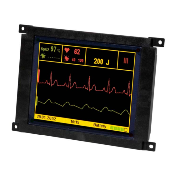
EL320.240-FA3 Multi-Color QVGA Display The EL320.240-FA3 thin film electroluminescent (EL) multi-color display is a high-performance alternative to QVGA (320 x 240) LCDs and is the ideal solution in demanding applications where superior visual performance, extreme temperature range, and environmental ruggedness are critical. -
Page 5: Installation And Set-Up
The EL320.240-FA3 mounting tabs were designed for a 3 mm screw. Mounting surfaces should be flat to within ±0.6 mm (±0.025"). Use all the mounting holes provided. -
Page 6: Avoiding Image Burn-In
(six bits each for red, green, and blue) as is common for AMLCD displays. Because the EL320.240-FA3 requires just 4 bits (two each for red and green), the 18 bits would need to be mapped into 4 bits. -
Page 7: Display Overlay Considerations
SGD data into the color data required by the EL320.240-FA3. SGD data is one bit per pixel, and 4 pixels of data are latched per video clock edge. The EL320.240-FA3 is 4 bits per pixel with one pixel of data latched per clock edge. Display Overlay Considerations Though not a requirement, often the end system will employ some type of transparent cover over the front the display. -
Page 8: Specifications And Operation
LUM0 and LUM1 settings. Typically, the 100C limit may be reached if the 12V input power exceeds 6W when the ambient temperature for the display electronics is 85C. EL320.240-FA3 Operations Manual -50°C to +85°C -50°C to +105°C 93% RH max at +40°C, per IEC 68-2-3 95% RH max at +55°C, per IEC 68-2-30... -
Page 9: Optical
(utilizing a three frame period with either a 33% or 66% duty cycle) generated by the display. Color G1 G0 Level EL320.240-FA3 Operations Manual >75 cd/m² max frame rate (LUM0=LUM1=0), yellow, center 95 cd/m² max frame rate (LUM0=LUM1=0), yellow, center >41 cd/m²... -
Page 10: Power
2) Typical power: pattern with 10% of pixels lit per row, typical display 3) All power numbers are for LUMA open (no analog dimming) EL320.240-FA3 Power vs. Percent of Pixels On, for All Three Percentage of pixels turned on (yellow) per row EL320.240-FA3 Operations Manual... -
Page 11: Display Interface
Input Note:1) DE is considered active if more than eight logic transitions are detected 2) SGD mode is similar to that of the Planar EL320.240.36 and EL320.240-HB displays but with required changes to the video data content to represent color... -
Page 12: Connector
(1-800-SAMTEC9) for the cable/connector options. Compatibility with non- Samtec equivalents should be verified before use. Figure: Data/Power Connector J1 Connector Pin Assignment Signal LUMA VCLK EL320.240-FA3 Operations Manual Pin 19 Pin 1 (Viewed from back of display) Signal LUM0 LUM1... -
Page 13: Display Input Descriptions
2. Input capacitance for all inputs except LUMA is 8 pF typical. 3. DE, LUM0, and LUM1 have > 20kohm pull-up resistors to 3.3V. 4. VS, SHUTDOWN, and V/Q have > 20kohm pull-down resistors to ground EL320.240-FA3 Operations Manual Units Notes -0.3... - Page 14 EL320.240-FA3 Operations Manual Page 14 of 25...
-
Page 15: Video Mode Timing
5) Video frame dithering/gray scale may cause artifacts due to the frame buffer 6) All timing measurements are made at 1.6V Horizontal Timing VCLK R/G data Vertical Timing First Line of Pixel Data EL320.240-FA3 Operations Manual Min. Max. Second Line of Pixel Data Units nsec nsec nsec... - Page 16 VCLK horizontal invalid data period R/G data Vertical Tim ing Line 1 vertical invalid data period R/G data EL320.240-FA3 Operations Manual Min. Max. VCLK period - 10 HS period - 340 VCLK period - 10 HS period – HS low...
- Page 17 VC LK horizontal invalid data period R/G data Vertical Tim ing Line 1 vertical invalid data period R/G data EL320.240-FA3 Operations Manual Min. Max. VCLK period - 10 HS period – HS low time After 7 HS rising edges first valid clock =...
- Page 18 VCLK horizontal invalid data period R/G data Vertical Tim ing Line 1 vertical invalid data period R/G data EL320.240-FA3 Operations Manual Min. Max. VCLK period - 10 HS period - 664 VCLK period - 10 28.33 HS period – HS low time...
- Page 19 R /G data V ertical Tim ing Line 1 vertical invalid data period R /G data EL320.240-FA3 Operations Manual Min. Max. VCLK period - 10 28.33 HS period – HS low time After 34 HS rising edges...
-
Page 20: Dimming
Dimming is used to reduce the display luminance to better match ambient conditions or to reduce power consumption. There are two methods for dimming the EL320.240-FA3 display. The preferred method is digital dimming, where the internal display frame rate is controlled using the LUM0 and LUM1 inputs. The internal frame rate is the frequency at which the drive voltage is applied to the display phosphor and thus impacts luminance and power consumption. -
Page 21: Self Test Mode
EL320.240-FA3 Analog Dimming Response, Typical LUMA voltage, volts Self Test Mode The display contains a self test mode composed of patterns displayed at the maximum frame rate for approximately four seconds each. Self test mode can be useful for verifying operation of the display. -
Page 22: Reliability
Mechanical Characteristics Display External Dimensions millimeters (inches) Weight (typical) Display Active Area millimeters (inches) Pixel Size millimeters (inches) Pixel Pitch millimeters (inches) EL320.240-FA3 Operations Manual width 150.3 (5.92) height 104.8 (4.13) depth 20.56 max (0.81) 198 g width 99.15 (4.05) height 74.36 (2.93) -
Page 23: Display Dimensions And Component Envelope
Note the 20.56 mm component envelope. This is the depth required by the display to ensure no interference with display board components, which are up to 12.19 mm in height. While tall components are the minority, Planar reserves the right to relocate components component envelope without prior customer notification. -
Page 24: Warranty
EL320.240-FA3 CC 997-3377-01LF Design and specifications are subject to change without notice. Planar Systems continues to provide optional, and in many cases custom, features to address the specific customer requirements. Consult Planar Sales for pricing, lead time and minimum quantity requirements. -
Page 25: Rohs
Support and Service Planar is a U.S. company based in Beaverton, Oregon and Espoo, Finland, with a world-wide sales distribution network. Application engineering support and service are available to make the integration of Planar displays as simple and quick as possible for our customers.